
Verification of Scenario-based Behavioural Models using
Capella and PyNuSMV
Simon Busard
1
, Christophe Ponsard
2
and Charles Pecheur
1
1
ICTEAM, Universit
´
e catholique de Louvain, Louvain-la-Neuve, Belgium
2
CETIC Research Centre, Charleroi, Belgium
Keywords:
Model-driven Engineering, Model Transformation, Verification, Model Checking, Sequence Diagrams,
Capella, Toolchain, Case Study.
Abstract:
Scenarios are widely use to capture a set of key system behaviours. They are part of standardised modelling
languages like UML and SysML. Precise semantics enable to analyse them at a formal level. In this paper,
we show how scenarios can be used to perform early checks on behavioural models in an industrial context
by providing a bridge between system modelling with Capella and the NuSMV model checker through the
PyNuSMV integration library and using hMSC semantics. Both the modelling front-end and verification back-
end are discussed and illustrated on a case study of unmanned aerial vehicles. Some interesting extensions to
increase the value of the integration are also identified and discussed.
1 INTRODUCTION
Software and system models rely on a variety of
languages captured by standards such as UML and
SysML (OMG, 1997)(OMG, 2005). The dynamic be-
haviour of a system is often modelled using scenarios
describing interactions among various types of sys-
tem actors (human beings, software services, hard-
ware devices...) in order to achieve functionalities
or maintain key properties like safety. Sequence di-
agrams are a widely used scenario notations part of
both UML and SysML. They offer a rich set of primi-
tives enabling to build elaborated scenarios including
alternatives, optional behaviours, loops... The reason
of their success compared to other formalisms like
state machines is that they are easy to use and under-
stand. They can also be applied from an early stage to
deal with high-level requirements by providing a set
of intended behaviours. Hence, their use have been
reported in a variety of industrial domains such as au-
tomotive (Sippl et al., 2019), railways (Tang et al.,
2010) and cyber-physical systems (Hu et al., 2020).
However such notations have some drawbacks as
they provide partial view on the system with no guar-
antee of completeness nor consistency in order to
guarantee possibly critical requirements. Detecting
such flaws early in the system design process is highly
desirable because it is known that the cost to fix is-
sues is raising exponentially as the development cy-
cle is progressing (Haskins et al., 2004). In order to
enable this kind of analysis, sequence diagrams must
have clearly defined semantics which is not the case
in the UML2 specification. However, several seman-
tics have been proposed and surveyed (Micskei and
Waeselynck, 2011). They differ in the way of repre-
senting the system events, the considered categories
of traces, whether they represent complete or partial
executions and the agent synchronisation mode be-
tween fragments. Based on this, fully automated for-
mal verification like model checkers can be used to
verify desired properties.
The purpose of this paper is to explore an early
verification toolchain by considering two comple-
mentary points of view:
• the industrial perspective is anchored in the mod-
elling notation without any knowledge of the un-
derlying verification technology. Inputs and diag-
nostics should be provided in a system modelling
editor through sequence diagrams. In our case,
the Open Source Capella industrial tooling is con-
sidered (Polarsys Fundation, 2015).
• the verification perspective requires a formal ver-
ification language and tooling. In our case,
we consider NuSMV model checker providing
an open architecture which can be reliably used
for the verification of industrial designs (Cimatti
et al., 2002).
Busard, S., Ponsard, C. and Pecheur, C.
Verification of Scenario-based Behavioural Models using Capella and PyNuSMV.
DOI: 10.5220/0010346103370343
In Proceedings of the 9th International Conference on Model-Driven Engineering and Software Development (MODELSWARD 2021), pages 337-343
ISBN: 978-989-758-487-9
Copyright
c
2021 by SCITEPRESS – Science and Technology Publications, Lda. All rights reserved
337
In order to reconcile both dimensions, it is neces-
sary to provide a mapping and interfacing between
both worlds. Our work adopts an approach based
on hMSC semantics of sequence diagrams close to
(Uchitel et al., 2004). We propose a model transfor-
mation using the convenient Python based PyNuSMV
library (Busard and Pecheur, 2013) and provide a
roundtrip integration with Capella. A validation is
performed on a middle-sized case study in the domain
of unmanned aerial vehicles (i.e. drones) composed
of 14 main scenarios organised in a structured way
and also covering 3 degraded scenarios.
This paper is structured as follows. First, Sec-
tion 2 presents the general architecture of our tool-
ing. Section 3 details the verification approach and
the NuSMV back-end. Section 4 introduces our drone
case study which is used in Section 5 to demonstrate
our integration with Capella and presents some val-
idation experiments. Section 6 discusses our results
over related work. Finally, Section 7 concludes and
presents some future work.
2 GENERAL ARCHITECTURE
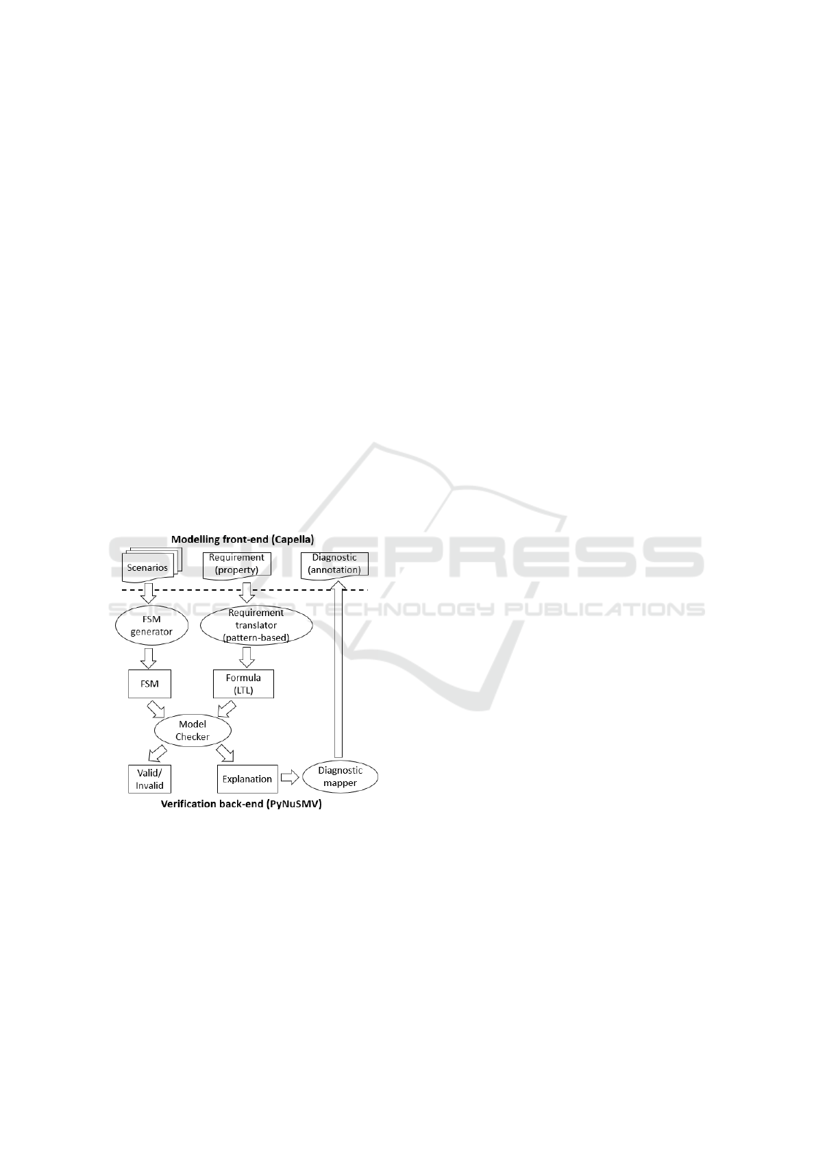
Figure 1: Tool architecture.
Figure 1 presents the general architecture of our tool-
ing which is composed of two distinct layers:
• the modelling front-end based on Capella supports
system modelling diagrams including UML2 se-
quence diagrams. Such diagrams are used to cap-
ture behaviours and can provide feedback about
counter-example scenarios.
• the verification back-end is based on the NuSMV
engine accessed through the PyNUSMV library
which provides Python integration primitives to
perform the necessary forward translation of se-
quence diagrams and properties to NuSMV au-
tomata as well as the backward translation of pos-
sible counter-example traces back to Capella.
The integration between both layers is achieved
though the Capella plugin extension mechanisms.
The verification is performed locally on the same ma-
chine with adequate binaries for NuSMV but the same
interface can easily be extended to invoke verification
as a web-service on a dedicated server.
3 BUILDING AND VERIFYING
BEHAVIOURAL MODEL FROM
SCENARIOS
Our approach is based on the synthesis of state-based
models from scenario-based models in order to per-
form verification tasks on the resulting model using
model checking technology, in our case NuSMV. Sev-
eral works have studied this kind of synthesis. A com-
plete survey in (Liang et al., 2006) covers different
source scenario-oriented models such as Message Se-
quence Charts, Live Sequence Charts or Sequence Di-
agrams, and different target state-based models such
as Statecharts, Automata or Petri nets.
In our case, scenarios are expressed as SysML se-
quence diagrams. Such diagrams are composed of
fragments used to provide structure based on opera-
tors like alternative, loop, parallelism, etc. The term
scenario refers to a set or linked sequence diagrams.
While the syntax of these diagrams is well defined,
they lack a clear and precise formal semantics.
Our semantics will consider that execution traces
of a scenario consist of labelled messages exchanged
synchronously between a sender actor and a receiver
actor. The considered traces may not contain other
messages than those specified in the sequence dia-
grams. Additionally, fragments appearing in a sce-
nario are sequenced in a weak way. This means that
an actor who has received or sent his last message
must not wait until the others have also finished send-
ing all their messages to be able to move on to the
next fragment.
Figure 2 presents a simple scenario between four
actors A, B, C and D, containing two alternatives. It
has four possible executions:
1. A sends m1 to B, then D sends m2 to C;
2. D sends m2 to C, then A sends m1 to B;
3. B sends m3 to A, then C sends m4 to D;
4. C sends m4 to D, then B sends m3 to A.
MODELSWARD 2021 - 9th International Conference on Model-Driven Engineering and Software Development
338
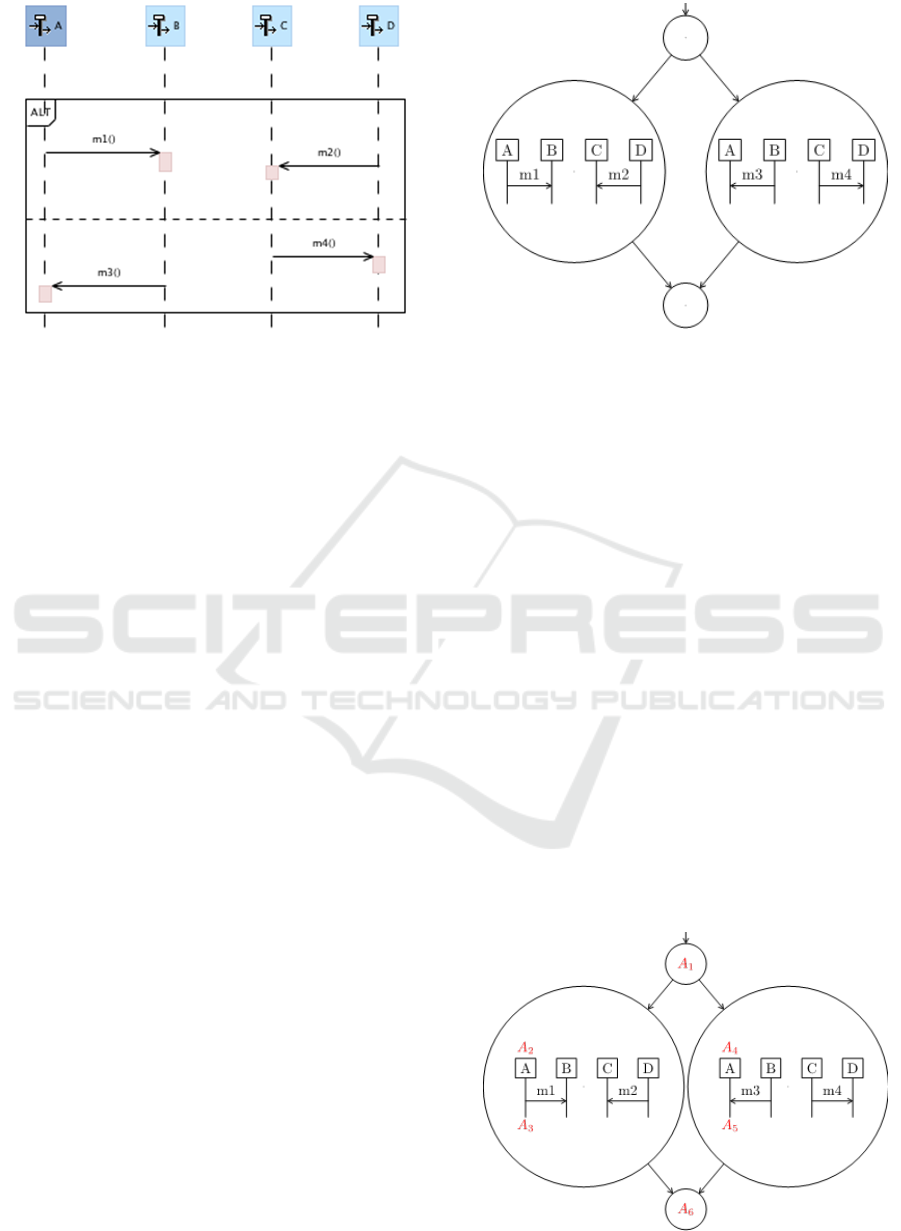
Figure 2: Sequence diagram will multiple execution traces.
The main motivations for our semantics is that:
• it enables to mark behaviours as either valid or
invalid and thus translate them into a finite state
machine (FSM) encoding valid behaviours.
• the synchronicity assumption is a simplification,
but does not in itself constitute a limitation be-
cause it is quite possible to introduce bounded
communication channels to model asynchronous
communication.
• the weak sequencing of fragment matches the (in-
formal) reference semantics for UML sequence
diagrams.
This semantics is also quite similar to the seman-
tics of High-level Message Sequence Charts (hMSCs)
(Mauw and Reniers, 1997). hMSCs are graphs where
the nodes are basic scenarios, i.e. a sequence of mes-
sages exchanged between actors. This similarity al-
lows us to translate a UML scenario into an hMSC.
For example, the hMSC depicted in Figure 2 is shown
in Figure 3. However, this translation requires re-
stricting the UML language. More specifically, the
UML language supports a large number of fragments
and also assertions types. Some are excluded be-
cause not supported by hMSC: negative behaviours,
”Break”, ”Ignore” and ”Consider” assertions. More-
over, we will further limit the considered fragments
to alternatives, optional behaviours, loops and paral-
lel behaviors, because they are the fragments encoun-
tered in our industrial validation case.
The benefits of translating SysML scenarios into
hMSCs are not only to rely on clear and well-
documented formal semantics but also to reuse ex-
isting work on how to extract a state machine en-
coding the hMSC behaviours, e.g. (Uchitel et al.,
2004)(Palshikar and Bhaduri, 2003). The considered
approach produces an FSM encoding the hMSC be-
haviours through the parallel composition of the FSM
Figure 3: hMSC translated from scenario of Figure 2.
of each actor with an additional controller FSM en-
suring that all the actors are making the same choices
during the system execution. Thus, it considers that
the state of each actor evolves through the hMSC
nodes and through the basic scenarios of these nodes.
The controller will enforce that any required choice to
transition to the next node will be applied in the same
way by all actors resulting in a consistent behaviour
with the initial hMSC.
More precisely, to build an actor FSM, the states
of each actor are identified based on the nodes and
basic scenarios of the hMSC. For example, Figure 4
shows the hMSC annotated with the possible states of
actor A:
• A is at the start of the scenario (state A1);
• A has decided to run the basic scenario on the left
(state A2);
• A sent message m1 to B (state A3);
• A has decided to run the basic scenario on the
right (state A4);
• A has received message m3 from B (state A5);
• A has finished executing the scenario (state A6).
Figure 4: hMSC annotated with state information.
Verification of Scenario-based Behavioural Models using Capella and PyNuSMV
339
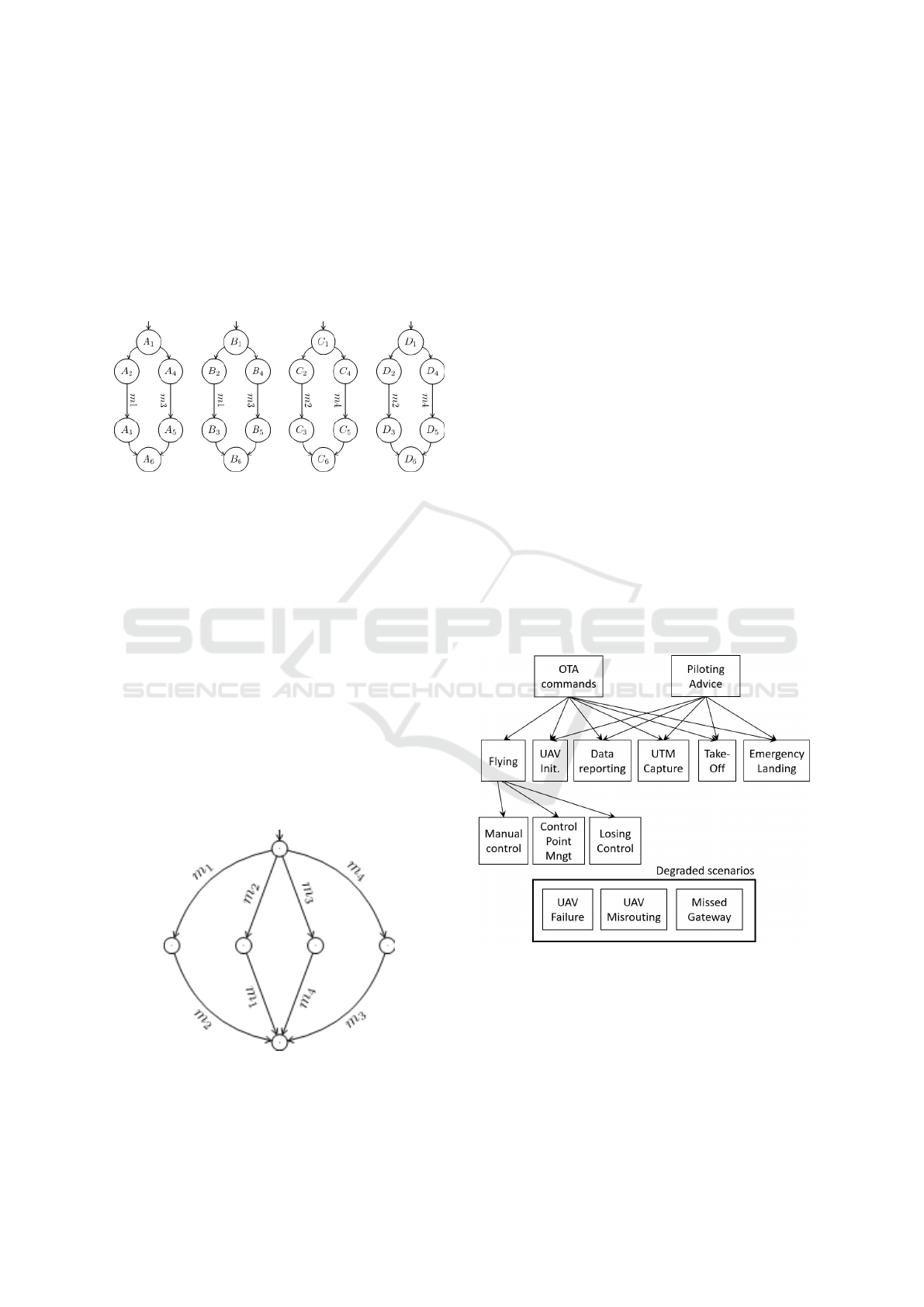
Once their states have been identified, the actor FSM
can be built by introducing a transition between two
states if the hMSC allows it. Figure 5 shows the
FSM of the actors of the hMSC presented in Fig-
ure 3. Note the FSMs of actors A and B are identi-
cal because, since the messages are exchanged syn-
chronously, there is no difference between sending
and receiving a message. The same holds for FSMs
of C and D.
Figure 5: Finite State Machines for the hMSC actors.
The additional controller ensures that all actors make
the same choices. In Figure 3, it must ensure that if
A and B are exchanging message m1, then C and D
will exchange message m2 and not message m4. The
number of states of such a controller grows quickly
because it must keep track of the path taken by each
actor in the hMSC, in order to force all actors through
the choices of the actor leading the execution. In our
simple case, the controller has 100 states.
Finally, the FSM encoding all the possible be-
haviours of the given hMSC, the trace model, results
from the parallel composition of the controller FSM
and the actors FSMs. The FSM encoding the be-
haviours of the scenario of Figure 2 and therefore of
the hMSC of Figure 3 has 118 states. However, it can
be reduced by hidding the transitions related to the
controller, resulting in the FSM shown in Figure 6.
Figure 6: Final trace model for hMSC of Figure 3.
This trace model can then be used for model check-
ing. In the scope of this paper, we only consider do-
mains specific properties specified in Linear Tempo-
ral Logic (LTL) (Manna and Pnueli, 1992). To ease
the encoding, we rely on a pattern languages inspired
from (Dwyer et al., 1999). It provides an easy way to
specify global properties ”Always” and ordering be-
tween events such as ”Before”, ”After”, ”Between”,
”Until”. The translation of such patterns in classical
LTL is pretty straightforward and not detailed here.
4 DRONE CASE STUDY
An unmanned aerial vehicle (UAV) or drone is an air-
craft without a human pilot on board. An unmanned
aircraft system (UAS) is composed of an UAV, a
ground-based controller, and a communications sys-
tem. UAV may operate under various degrees of au-
tonomy: either under remote control by a human op-
erator or autonomously, under the control on an au-
topilot. The unmanned aircraft system traffic manage-
ment (UTM) is in charge of autonomously controlled
operations of an UAS. It implements operational con-
cepts, data exchange requirements, and a framework
enabling multiple UAS operations beyond visual line-
of-sight (Airbus, 2019). For this purpose, it relies on a
specific component that we named Autonomous Op-
eration System (AOS).
Figure 7: Structure of the case study scenarios.
Our case study is based on scenarios from a re-
quirements analysis of drone information manage-
ment (Mennella et al., 2018) and a set of scenarios
gathered in our local Belgian ecosystem through two
emergence workshops[reference removed]. This re-
sulted in the identification and specification of 14 sce-
narios. Those are organised under two main scenarios
covering a large part of the system and 3 additional
MODELSWARD 2021 - 9th International Conference on Model-Driven Engineering and Software Development
340
degraded scenarios as shown in Figure 7. The next
section illustrates the processing of a specific scenario
related to the drone capture and also gives some statis-
tics on the full set of scenarios (Nihoul et al., 2019)
5 INTEGRATION AND
VALIDATION IN CAPELLA
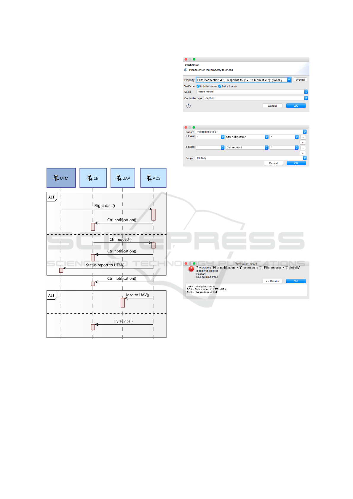
Figure 8 shows a standard sequence diagram of
Capella specifying the UAV Traffic Management
(UTM) capture scenario. It is composed of 4 lifelines
involving respectively the UTM, the Human Con-
troller (Ctrl), the UAV and the AOS.
Figure 8: UTM capture scenario.
A verification dialog depicted in Figure 9 can be trig-
gered from a sequence diagram in order to capture a
property for model checking and different technical
parameters related to the FSM generation process de-
scribed in Section 2.
In order to ease the capture of the property, a wiz-
ard supporting different classical LTL specification
patterns can be triggered from the verification win-
dow. Figure 10 shows the wizard for a Respond pat-
tern stating that each occurrence of a request should
be followed by a notification response.
Figure 9: Verification dialog.
Figure 10: Pattern-based wizard for the verification prop-
erty.
The verification process then goes through model
transformation chain detailed in Section 2 including
the NuSMV-based verification engine described in
Section 3 to yield a result which is valid in this case
as the Ctrl notification always responds to a Ctrl re-
quest. In case the request is dropped, the result will
yield a counter-example scenario as depicted in Fig-
ure 11. Note that in the current version this counter-
example is only presented in textual for and not yet as
a sequence diagram.
Figure 11: Counter-Example scenario for invalid property.
Table 1 shows global summary of the test performed
on our 14 validation cases. For each scenario, it de-
tails the number or agents, the fact it is bounded, the
number of hMSC nodes and the size of the resulting
trace model.
First, the two main scenarios about Over the
Air (OTA) commands and piloting advice cannot be
checked because they are not bounded and so their
behaviours cannot be encoded within an FSM. Such
information is already useful and a separate bounded-
ness check of the scenario is provided as support for
this. Two other scenarios (flying and data reporting)
revealed too complex to be managed within reason-
able time (the generation was limited to 1 hour on a
standard laptop). Other scenarios could be processed
with success with a model complexity varying from
very few states up to about 65000 states.
Verification of Scenario-based Behavioural Models using Capella and PyNuSMV
341

Table 1: Validation summary.
Scenario Agents Bounded hMSC Trace
nodes model size
OTA commands 7 no 41 N/A
UAV init 3 yes 15 15
Take off 3 yes 1 3
Flying 3 yes 17 N/A
Manual control 3 yes 8 64131
Control pt mgnt 4 yes 7 652
Losing control 3 yes 4 41
Data reporting 7 yes 6 N/A
UTM capture 4 yes 6 402
Emerg. landing 3 yes 4 52
Piloting advice 6 no 25 N/A
DEG: UAV failure 4 yes 8 2393
DEG: mis-routing 4 yes 1 5
DEG: missed g-way 3 yes 1 4
6 DISCUSSION OVER RELATED
WORK
Scenario-based modelling and verification has been
applied in the railway domain to help transitioning
from a strong document-based system development
culture to a more model-based approach (Tang et al.,
2010). In this work, relevant operational scenarios are
extracted from the specification to construct UML se-
quence diagrams which are verified by a formal anal-
ysis tool. As in our work, NuSMV was used and
the output analysis helping in producing the docu-
ment quality. A notable difference is that in our work,
a model-based approach is already partly in place
and that specification documents are being generated
through model to text generation and update mecha-
nisms (Michot et al., 2018). We could also success-
fully apply our tooling to ATO over ETCS industrial
problem.
Scenario-based approaches are also being consid-
ered in the systems engineering for automated driving
functions (Sippl et al., 2019). The aim is to propose
a method for continuous usage of scenarios embed-
ded in the systems engineering process which could
help to divide complex and intangible development
goals in smaller solvable tasks. The proposed ap-
proach is more general and not anchored in sequence
diagrams but advocating for a standard called Open-
SCENARIO. The incremental aspect of the approach
is interesting and we believe using sequence diagrams
at some point to provide semantics and checking ca-
pabilities can help avoiding regression in evolving set
of scenarios or dealing with product families.
Another variant of scenario relies on Life Se-
quence Charts (LSC) rather than (h)MSC (Damm and
Harel, 2001). It allows the distinction between pos-
sible and necessary behaviours both globally, on the
level of an entire chart and locally, when specify-
ing events, conditions and progress over time within
a chart. A methodology called Play-In Play-Out
supports the capture and animation-based validation
through LSCs (Harel and Marelly, 2003) and also the
verification through smart play-out which relies on
model checking and planning algorithms. It has been
used for the verification of a telecommunication sys-
tem (Combes et al., 2005). However, the focus is
more to run scenarios and to avoid some of the vio-
lations related to naive execution.
In addition to the verification of domain specific
properties, more general checks can also be consid-
ered. Among them the detection of implied scenarios
is interesting in the context of scenario-based design.
Such scenarios are defined as an execution which is
not authorized by the scenario, but which is possible if
we consider that the different actors of the scenario do
not consult each other but only rely on the exchanged
messages to infer the choices made by other actors
(Uchitel et al., 2004). In short, it means we consider
the system without any controller enforcing the same
choice. This check is justified as such a controller is
usually hard or even impossible to implement given it
must discuss will all actors. In addition, it would be
very inefficient. Technically, this can be implemented
by removing the controller from the trace model to
produce an architectural model that represents the be-
haviours of the system composed of separated actors
not worrying about synchronizing their choices. The
verification could be done by performing an exhaus-
tive search of the synchronised models until a trace
is found in the more permissive architectural model
which is not part of the trace model. If the search fails,
the hMSC does not have any implied scenarios. The
absence of implied scenarios also eases further verifi-
cation activities since model checking can just focus
on the equivalent architectural model which is simpler
to encode and to verify than the full trace model. Such
an extension is easy to implement through our flexible
PyNuSMV framework and is being considered.
Another interesting verification approach involv-
ing sequence diagrams is to perform containment
checking, i.e. check that low-level sequence diagrams
produced in design steps are enforcing the behaviours
stated through higher-level sequence diagrams from
the requirements phase (Muram et al., 2016). This
approach makes a lot of sense as system development
usually proceeds through functional refinement from
system to subsystems with the production of scenar-
ios at different levels of details. In the proposed ap-
proach, high-level properties are translated into LTL
formulas and lower level properties into automata as
MODELSWARD 2021 - 9th International Conference on Model-Driven Engineering and Software Development
342

in our approach. Our tooling could evolve to support
such an approach, however low-level scenarios being
more operational, they must support strict sequencing
which is not the case of our current approach.
7 CONCLUSION & NEXT STEPS
In this paper, we proposed an integration of automated
verification of sequence diagrams inside the Capella
Open Source industrial platform used as modelling
front-end. For the verification back-end, we used the
reliable NuSMV model checker and the PyNuSMV li-
brary as flexible development and integration library
to produce a precise mapping based on hMSC se-
mantics. Our work could be validated on a drone
case study. It confirmed the tool capabilities although
with some limitations when dealing with bigger or un-
bounded models.
The comparative discussion with the literature
highlights interesting ways to extend our work while
keeping the same approach: supporting the verifica-
tion of implied scenarios and of containment relation-
ships. On the implementation side, in order to make
our work easier to deploy and reduce the need to sup-
port different target platform, we also plan to imple-
ment the verification as a web service. We also plan to
further validate the performance and usability of our
improved tooling in other domains such as automotive
and railways.
REFERENCES
Airbus (2019). What is unmanned traffic manage-
ment ? https://www.airbus.com/newsroom/stories/
what-is-unmanned-traffic-management-utm.html.
Busard, S. and Pecheur, C. (2013). PyNuSMV: NuSMV as
a Python Library. volume 7871 of LNCS, pages 453–
458. Springer-Verlag.
Cimatti, A. et al. (2002). NuSMV 2: An Open Source Tool
for Symbolic Model Checking. In Computer Aided
Verification, pages 359–364. Springer Berlin Heidel-
berg.
Combes, P., Harel, D., and Kugler, H. (2005). Modeling and
verification of a telecommunication application using
live sequence charts and the play-engine tool. In Proc.
of the Third Int. Conf. on Automated Technology for
Verification and Analysis, ATVA’05.
Damm, W. and Harel, D. (2001). LSCs: Breathing life into
message sequence charts. Formal methods in system
design, 19(1):45–80.
Dwyer, M. B., Avrunin, G. S., and Corbett, J. C. (1999).
Patterns in property specifications for finite-state ver-
ification. In Proc. of the 21st Int. Conf. on Software
Engineering. Association for Computing Machinery.
Harel, D. and Marelly, R. (2003). Come, Let’s Play:
Scenario-Based Programming Using LSC’s and the
Play-Engine. Springer-Verlag, Berlin, Heidelberg.
Haskins, B. et al. (2004). Error cost escalation through the
project life cycle. In INCOSE International Sympo-
sium, volume 14. Wiley Online Library.
Hu, M. et al. (2020). Quantitative timing analysis
for cyber-physical systems using uncertainty-aware
scenario-based specifications. IEEE Transactions on
Computer-Aided Design of Integrated Circuits and
Systems, 39(11):4006–4017.
Liang, H., Dingel, J., and Diskin, Z. (2006). A comparative
survey of scenario-based to state-based model synthe-
sis approaches. In Proc. Int. Workshop on Scenarios
and State Machines: Models, Algorithms, and Tools.
Manna, Z. and Pnueli, A. (1992). The Temporal Logic of
Reactive and Concurrent Systems. Springer-Verlag.
Mauw, S. and Reniers, M. (1997). - high-level message
sequence charts. In Cavalli, A. and Sarma, A., editors,
SDL ’97: Time for Testing, pages 291 – 306. Elsevier
Science B.V.
Mennella, A. et al. (2018). Scenarios identification and re-
quirement analysis of drone information management.
Deliverable D3.1 Sesar DREAMS project.
Michot, A., Ponsard, C., and Boucher, Q. (2018). Towards
better document to model synchronisation: Experi-
mentations with a proposed architecture. In Proc. of
the 6th Int. Conf. on Model-Driven Engineering and
Software Development, MODELSWARD.
Micskei, Z. and Waeselynck, H. (2011). The Many Mean-
ings of UML 2 Sequence Diagrams: A Survey. Softw.
Syst. Model., 10(4):489–514.
Muram, F. U., Tran, H., and Zdun, U. (2016). A model
checking based approach for containment checking of
uml sequence diagrams. In 23rd Asia-Pacific Software
Engineering Conference (APSEC). IEEE.
Nihoul, B. et al. (2019). Drone workshops for us-
age scenario elicitation. CETIC http://bit.do/
emergence-workshop.
OMG (1997). Unified modeling language. http://www.omg.
org/spec/UML.
OMG (2005). System modeling language. http://www.omg.
org/spec/SysML.
Palshikar, G. K. and Bhaduri, P. (2003). Verification of
scenario-based specifications using templates. Proc.
of the Int. Workshop on Software V&V (SVV).
Polarsys Fundation (2015). Capella system modelling tool.
http://www.polarsys.org/capella.
Sippl, C. et al. (2019). Scenario-based systems engineer-
ing: An approach towards automated driving function
development. In IEEE Int. Systems Conference.
Tang, W., Ning, B., Xu, T., and Zhao, L. (2010). Scenario-
based modeling and verification of system require-
ment specification for the european train control sys-
tem. WIT Transactions on the Built Environment,
114:759–770.
Uchitel, S., Kramer, J., and Magee, J. (2004). Incremental
elaboration of scenario-based specifications and be-
havior models using implied scenarios. ACM Trans.
Softw. Eng. Methodol., 13(1):37–85.
Verification of Scenario-based Behavioural Models using Capella and PyNuSMV
343
