
Short-reach 200 Gb/s SDM Network Employing Direct-detection and
Optical SSBI Mitigation
Tiago D. Freitas M.
1 a
, Tiago M. F. Alves
1,2 b
and Adolfo V. T. Cartaxo
1,2 c
1
ISCTE - Instituto Universit
´
ario de Lisboa, Lisbon, Portugal
2
Instituto de Telecomunicac¸
˜
oes, Lisbon, Portugal
Keywords:
Signal-signal Beat Interference, Direct-detection, Multicore Fibre, Optical Fibre Communications, Space
Division Multiplexing, Short-reach Networks.
Abstract:
We propose a new transmission scheme for direct-detection (DD) short-reach networks based on transmitting
the carriers and the data signals in separated cores of a multicore-fibre (MCF). With this scheme, a low com-
plexity signal-signal beat interference (SSBI) mitigation approach is proposed at the receiver side, which may
be required to compensate electronically the chromatic dispersion of the singlemode fibre. The performance
of a 200 Gb/s binary NRZ signal in a MCF short-reach network employing the proposed transmission scheme
is assessed by numerical simulation. The combined effect of the skew and the laser phase noise on the system
performance is evaluated. It is shown that the SSBI mitigation technique enables distances up to 180 m when
dispersion is not compensated, showing the potential to be implemented in intra data-centre (DC) networks,
when the signal mean optical power is much higher than the carrier mean optical power, and when the SSBI
estimation is not corrupted by electrical noise. The results also show that in systems with full dispersion
compensation, a significant performance improvement is achieved by the proposed SSBI mitigation approach,
enabling higher connection lengths.
1 INTRODUCTION
Optical fibre networks are facing an exponential
growth on the capacity demands (Cisco, 2018). Space
division multiplexing (SDM) technology is pointed
out as a solution to overcome the so-called capac-
ity crunch (around 100 Tb/s per fibre) (Butler et al.,
2017). Short-reach connections, such as intra data-
centre (DC) connections, are experiencing continuous
data traffic increase, and this phenomenon brings con-
strains such as space limitations and the need to max-
imize the throughput of each connection (Kachris and
Tomkos, 2012). Multicore fibres (MCFs) are one of
the new technologies brought by SDM. This technol-
ogy can enhance the network capacity by transmit-
ting data simultaneously on a high number of fibre
cores. Recent experiments on MCFs achieved capaci-
ties of up to 2.05 Pb/s using a few-mode MCF (Soma
et al., 2015) and 2.15 Pb/s using a 22 core homoge-
neous single-mode (SM) MCF (Puttnam et al., 2015),
a
https://orcid.org/0000-0002-6841-4061
b
https://orcid.org/0000-0001-7382-0737
c
https://orcid.org/0000-0002-4514-2737
well beyond the fundamental limit of SM single core
fibres. In MCFs, the fibre capacity can be theoreti-
cally increased by N times, where N represents the
number of independent cores that are incorporated in
the same fibre cladding. The number of cores, and
the core-to-core distance, will determine the inter-
core crosstalk (ICXT) levels. In the particular case of
weakly-coupled homogeneous MCFs, different cores
of the same fibre present identical core properties and,
thus, the ICXT arises due to the coupling between
cores. Nevertheless, in short-reach networks, the im-
pact of the crosstalk on the system is reduced due to
the small accumulated ICXT. Therefore, this type of
MCF presents high potential to be employed in DC
connections (Hayashi et al., 2019).
In short-reach networks, low cost and complexity
are crucial requirements. Thus, direct-detection (DD)
receivers are preferable for these networks since they
are cheaper, smaller and less power hungry than co-
herent detection systems (Cartledge and Karar, 2014).
Still, these receivers cause, due to the square law de-
tection of a single photodiode, performance degrada-
tion induced by signal-signal beat interference (SSBI)
(Ishimura et al., 2019). The SSBI can be mitigated
122
M., T., Alves, T. and Cartaxo, A.
Short-reach 200 Gb/s SDM Network Employing Direct-detection and Optical SSBI Mitigation.
DOI: 10.5220/0010343101220130
In Proceedings of the 9th International Conference on Photonics, Optics and Laser Technology (PHOTOPTICS 2021), pages 122-130
ISBN: 978-989-758-492-3
Copyright
c
2021 by SCITEPRESS – Science and Technology Publications, Lda. All rights reserved
using complex digital signal processing (DSP) tech-
niques (Ju et al., 2015), (Nezamalhosseini et al.,
2013), which are highly undesired in short-reach net-
works due to the high costs associated.
In this work, a new transmission scheme based on
MCFs and with high potential to mitigate the SSBI
with reduced complexity is proposed. This scheme is
based on transmitting the virtual carriers, that are used
to assist the detection, and the data signals in sep-
arated cores of the weakly-coupled MCF. With this,
estimation and mitigation of the SSBI at the receiver
without resorting to complex DSPs can be achieved.
This low complexity SSBI mitigation technique may
be of particular interest for DD systems where SSBI
mitigation is required at the receiver side prior to
employ digital techniques to mitigate the impact of
the dispersion impairments on the detected data sig-
nal. Also, with the proposed transmission scheme,
in which the carriers are transmitted independently
from the data signals, additional cost savings may be
achieved in bidirectional networks. This occurs be-
cause local lasers can be replaced by a single optical
comb with carriers being distributed as optical seeds
in a single MCF core along the whole network.
The performance of the proposed transmission
scheme is assessed by evaluating the impact of the
combined effect of the skew and the laser phase noise
on the performance of MCF-based short-reach net-
works. Also, the improvement of the performance
due to the SSBI mitigation technique is studied, which
can afterwards potentiate the use of simple DSP tech-
niques to electronically remove the dispersion effects
on the signal.
2 PROPOSED TRANSMISSION
SCHEME
2.1 Concept Description
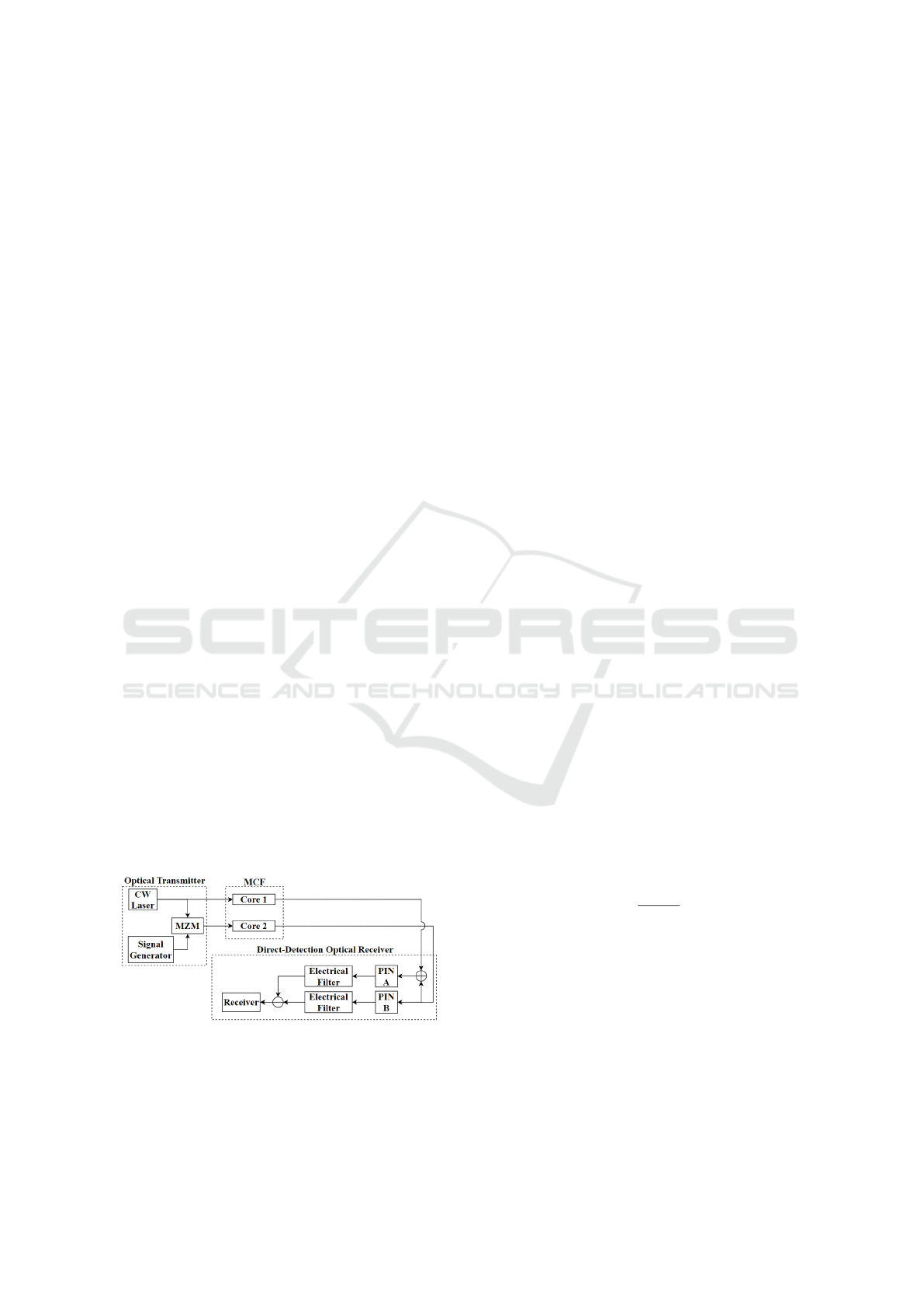
Figure 1: Equivalent model of the MCF-based transmission
scheme with DD and SSBI removal.
Figure 1 presents the proposed MCF-based transmis-
sion scheme with one core (core 1) dedicated to sup-
port only the carriers transmission. The optical trans-
mitter (TX) consists in two branches. One branch
generates the optical carrier to be transmitted in core
1. This optical carrier is used at the receiver (RX)
side to assist the detection. The other branch gener-
ates the optical data signal with carrier suppression.
The outputs of the TX are transmitted into two differ-
ent cores of the MCF. When transmitting data in two
different cores, the signals (carrier and data signal)
suffer different delays. The relative delay between
the signals at the cores output, i.e., the skew, is cru-
cial when adding up the signals. This occurs because
the combined effect of the skew and the laser phase
noise may lead to destructive interference at the re-
ceiver side causing performance degradation.
After fibre propagation, the DD-based RX pho-
todetects the signals performing the optical to elec-
trical conversion. In the positive-intrinsic-negative
(PIN) photodiode A, after adding the carrier and the
data signal in the RX input, the photodetection of the
resulting optical signal is performed. As a result of
the photodetection process, an unwanted SSBI term
is originated along with the wanted data signal. In
PIN B, the carrier suppressed data signal, that the pro-
posed transmission scheme allows to obtain, is pho-
todetected. This allows to estimate separately the
SSBI component. Then, this SSBI term is used to
subtract the SSBI term originated in PIN A (where the
desired signal is located), obtaining, ideally, a SSBI
free signal.
2.2 Transmission Scheme Limitations
The performance of the proposed transmission
scheme strongly depends on the delay suffered by
the signals in different fibre cores, and in particular
the skew between the two cores. The relation be-
tween the skew and the laser phase noise coherence
time, t
c
, can provide a solid estimation about how
the skew may impact the system performance due to
phase noise. The laser phase noise coherence time is
given by (Goodman, 2015)
t
c
=
1
π · ∆ν
L
(1)
where ∆ν
L
is the laser linewidth. If the laser elec-
trical field at two different time instants, t and t + T,
is considered, the coherence time can be defined as
the maximum T value for which the phase difference
between the electric field at the two instants remains
predictable. If t
c
is much longer than the skew, the
degradation caused by the phase noise is small since
the relative delay time between the two cores leads to
a situation where, at a given time instant, the phase
noise at the output of the two cores has similar am-
plitudes. In this case, when the carrier is added to the
Short-reach 200 Gb/s SDM Network Employing Direct-detection and Optical SSBI Mitigation
123

signal, no destructive interference occurs. Contrarily,
if t
c
is not much longer than the skew, the degradation
caused by the laser phase noise can be significant.
Since the DD receiver photodetects each signal
through a PIN photodiode, the current associated with
the carrier-added data signal (output of PIN A), con-
sidering the skew and the laser phase noise, can be
written as (for a PIN responsivity of 1 A/W):
i
A
(t) = |A
c
e
jφ
n
(t)
+ s(t − T )e
jφ
n
(t−T)
|
2
(2)
where A
c
is the carrier amplitude, s(t) is the data sig-
nal at the MCF output, T is the skew between cores
and φ
n
(t) is the laser phase noise.
Based on equation 2, the aforementioned relation
between t
c
and the skew can be mathematically ex-
pressed. If the skew is much shorter than t
c
, then
e
jφ
n
(t−T)
≈ e
jφ
n
(t)
(3)
resulting for the current at the output of PIN A:
i
A
(t) ≈
A
c
+ s(t − T )
· e
jφ
n
(t)
2
=
A
c
+ s(t − T )
2
(4)
In this case, the received signal is not impaired
by the laser phase noise. As opposed, in the sce-
nario where t
c
is not sufficiently longer than the skew,
equation 3 is not verified and so the phase noise is
not eliminated when the signal is photodetected, caus-
ing phase-to-intensity noise conversion, which will be
analysed further on.
One of the main goals of this work is to identify
the conditions under which a negligible degradation
due to the combined effect of the skew and the laser
phase noise is obtained. When the degradation due to
the skew and the laser phase is negligible, the current
at the output of PIN A is given by (from equation 4,
for a PIN responsivity of 1 A/W):
i
A
(t) = A
2
c
+ 2 · A
c
· ℜ{s(t − T )} + |s(t − T )|
2
(5)
In this scenario, there are two major impairments that
can cause performance degradation: the SSBI (last
term) and the chromatic dispersion. The delay, T , is
due to the propagation and can be compensated with-
out causing distortion. The dispersion effect is repre-
sented in the term s(t) as follows
s(t) = s
in
(t) ∗ h(t) (6)
where s
in
(t) is the data signal at the MCF input, ”∗”
is the convolution operator and h(t) is the impulse
response of the SM fibre, which contains the atten-
uation and dispersion effects of the MCF. It is pos-
sible to electronically remove the dispersion effects
(from Equation 5) through DSP techniques. How-
ever, this can be performed only after the SSBI term
is removed. This SSBI removal process is analysed in
Section 4.
3 SYSTEM SETUP
In this work, a 200 Gb/s polar nonreturn-to-zero
(NRZ) signal is considered. A continuous wave (CW)
laser generates the optical carrier, affected by the
phase noise. The model used to describe the laser
phase noise is a Wiener process (Peng, 2010) charac-
terized by the laser linewidth (∆ν
L
). The NRZ signal
is converted into the optical domain using a single-
arm chirpless Mach-Zehnder modulator (MZM), bi-
ased at the minimum bias point in order to generate
the optical signal with suppressed carrier. For the
optical transmission, a two core MCF is considered.
One core is used to transmit the 200 Gb/s NRZ signal
and the other core is used to transmit the carrier. In the
case of a wavelength division multiplexing (WDM)
system, the optical carriers used to assist the detec-
tion of the different NRZ signals would be all trans-
mitted in the same core. The selection of the proper
carrier at the RX side is performed after carrier de-
multiplexing. Linear propagation along each SM core
is assumed, with a dispersion parameter of approx-
imately 18 ps/nm/km and a fibre attenuation coeffi-
cient of 0.21 dB/km.
Since the RX is based on DD, a single photodetec-
tor is considered for each branch. The photodetection
is performed by PIN photodetectors with a responsiv-
ity, R
λ
, of 1 A/W, followed by an electrical filtering
using a third-order Bessel filter with a -3 dB cutoff
frequency of 160 GHz.
In this IM-DD system, the evaluation of the degra-
dation induced by the system impairments is firstly
done by assessing the eye-opening penalty (EOP),
which gives a fast estimation of the signal quality, that
can reflect the effects of signal distortion and eye clo-
sure due to the noise. The EOP is given by
EOP = −10 · log
10
I
1
− I
0
2I
av
[dB] (7)
where I
1
represents the lowest current level associ-
ated with bits 1 and I
0
represents the highest current
level associated with bits 0, both values being taken at
the time instant for which the eye-diagram opening is
maximum. I
av
is the detected current corresponding
to the average power given by
I
av
= (P
s
+ P
c
) · R
λ
(8)
where P
s
is the NRZ signal mean optical power and P
c
is the carrier mean optical power, both powers being
calculated at the RX input. As 2 I
av
is the greatest eye-
opening that can be obtained, when I
1
− I
0
is equal to
2I
av
the EOP is 0 dB.
To further assess the system performance, by
quantifying the impact of the skew, the laser phase
noise and the dispersion, the bit error ratio (BER)
PHOTOPTICS 2021 - 9th International Conference on Photonics, Optics and Laser Technology
124
- calculated through the direct-error counting (DEC)
method - is used as figure of merit. The BER is eval-
uated before and after SSBI removal results, in order
to identify the scenarios in which the proposed SSBI
mitigation technique is of particular interest, i.e, when
the technique provides system performance improve-
ment.
4 RESULTS AND DISCUSSION
In this section, the impact of the skew, the phase-to-
intensity noise conversion and the chromatic disper-
sion is assessed. This is accomplished by analysing
EOP and BER results, evaluating the system perfor-
mance and the improvement obtained by employing
the proposed transmission scheme and SSBI mitiga-
tion approach.
4.1 Skew Impact on the
Phase-to-intensity Noise Conversion
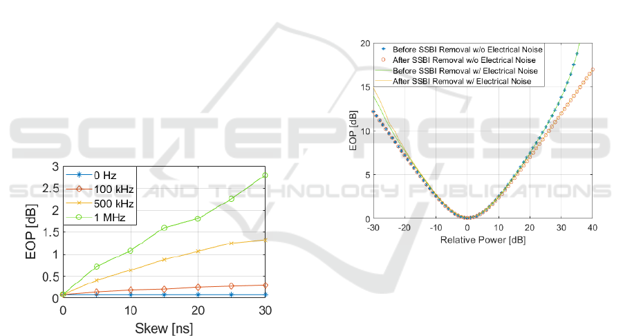
Figure 2 shows the impact of the skew on the EOP
of the detected NRZ signal and how the results are
affected by the laser linewidth. The results of Figure 2
consider only the skew and phase noise impairments.
A MCF length of 2 km is considered.
Figure 2: EOP as a function of the skew, for different laser
linewidths.
The null linewidth results offer a baseline com-
parison, allowing to quantify in terms of EOP the im-
pact of the skew compared to the ideal case, where the
skew does not impair the system. Different linewidths
impact the system performance differently for the
same skew. For a skew of 30 ns, linewidths of 500
kHz and 1 MHz show a EOP above 1.5 dB, while the
EOP for a linewidth of 100 kHz is not significantly
affected by any of the tested skew values.
4.2 Assessment of Beneficial Conditions
for SSBI Removal
First and foremost, it is needed to determine un-
der which conditions the proposed SSBI removal ap-
proach is effective. The SSBI component is gener-
ated from the NRZ signal after photodetection. When
the carrier power is much higher than the NRZ sig-
nal power, the performance is impaired mainly by the
noise levels and the SSBI term is negligible. Other-
wise, the system performance is dominantly impaired
by the SSBI. From Equation 5, we conclude that the
impact of the SSBI term depends on the ration be-
tween the carrier and the signal mean optical power.
Figure 3 shows the EOP as a function of the rela-
tive power, P
r
, defined as the ratio between the signal
mean optical power (P
s
) and the carrier mean opti-
cal power (P
c
). The results were obtained with and
without considering electrical noise, and for a P
c
of 0
dBm.
Figure 3: EOP as a function of the relative power, before
and after SSBI removal, with and without electrical noise.
When the relative power is lower than 0 dB, the
EOP reflects the eye-closure due to the lowering of
P
s
values. It is also seen that under these conditions,
removing the SSBI can worsen the results, in the pres-
ence of electrical noise. This happens because when
subtracting the output of PIN A with the output of PIN
B, in fact two random and independent noise compo-
nents with the same power are being added. On the
other side, for P
r
higher than 0 dB, the SSBI removal
may show improvements. In this study, for these P
r
values, the SSBI term is dominant over the electri-
cal noise power considered, and so the electrical noise
does not affect the retrieved signal in terms of the EOP
in a visible manner.
Other study is conducted to understand the im-
pact of the dispersion effects on the performance of
the system operating at the identified ”ideal point”,
where the signal and carrier mean optical powers are
Short-reach 200 Gb/s SDM Network Employing Direct-detection and Optical SSBI Mitigation
125
the same. Figure 4 shows the EOP as a function of
the MCF length, for different laser linewidths, with
and without dispersion considered in the fibre and for
a P
r
of 0 dB. The walk-off is given as a input param-
eter to the system instead of the skew.
(a)
(b)
Figure 4: EOP as a function of the MCF length for differ-
ent laser linewidths, with and without dispersion, for: (a) a
walk-off of 1 ns/20 km and (b) a walk-off of 10 ns/20 km.
Results of Figure 4 show that the dispersion
clearly constrains the system even if working in the
ideal situation (where P
r
is 0 dB), showing a mini-
mum of 2.5 dB penalty for all laser linewidths for dis-
tances higher than 200 m. For both walk-off values
studied, the dispersion is the main impairment respon-
sible for the degradation, but it is noticeable that in-
creasing the walk-off increases slightly the EOP. This
happens because increasing the walk-off originates a
higher skew for a given distance, and then the com-
bined effect of the skew and the increasing laser phase
noise (broader linewidths) leads to an additional per-
formance penalty due to phase-to-intensity noise con-
version. From the results in Figure 4, it is possible to
conclude that even if considering the P
r
that gives the
best performance (based on Figure 3), the system is
impaired by the dispersion, and this effect overcomes
all other effects considered, thus being the most sig-
nificant. For this reason, if system performance im-
provement is required, dispersion needs to be fully
compensated.
As shown in equation 5, for the dispersion to be
compensated electronically at the RX side, the SSBI
term needs to be successfully mitigated. As it was
seen in Figure 3, an efficient SSBI mitigation only
occurs for high P
r
. A similar study to the one pre-
sented in Figure 3, now considering the BER as the
performance metric, is carried out. Electrical noise
is again considered, but now it is categorised by the
signal-to-noise ratio (SNR), defined as:
SNR =
P
tot
P
noise
(9)
where P
tot
is the carrier-added NRZ signal mean
power at the output of PIN A and P
noise
is the noise
power. From equation 9, given a certain SNR value
under test and the mean power of the received signal
imposed by P
r
, P
noise
is determined and used to sim-
ulate the noise component added after photodetection
on both branches (PIN A and B).
Figure 5 shows the BER as a function of the P
r
,
before and after SSBI removal, for different SNR val-
ues. These results were obtained without consider-
ing skew, laser phase noise and dispersion, in order to
firstly assess the SSBI mitigation technique effective-
ness in a more favorable scenario, where only electri-
cal noise is considered. Under these conditions, the
SSBI mitigation is not impaired by the phase noise
nor the dispersion. Figure 5 shows that the SSBI mit-
igation for values of P
r
under 15 dB only degrades
the BER, meaning that, for the SNR values consid-
ered, the SSBI estimation is corrupted by the elec-
trical noise and, thus, no effective SSBI mitigation
is achieved. In accordance with the results shown in
Figure 3, the SSBI removal is not effective for these
P
r
tested values.
Figure 5: BER as a function of the relative power before
(continuous line) and after (dashed line) SSBI removal for
a SNR of: 12 (blue), 13 (red), 14 (yellow), 15 (purple) and
16 (green) dB.
In Figure 6, an extension of Figure 5 to relative
powers between 15 and 25 dB is shown. With this,
system situations in which the SSBI is more powerful
are tested. The sub-figures of Figure 6 consider two
different sets of SNR values that were tested. When
PHOTOPTICS 2021 - 9th International Conference on Photonics, Optics and Laser Technology
126
the SNR is increased, converging to a ”no-electrical
noise” scenario, a BER improvement is obtained af-
ter SSBI mitigation. This indicates that, under these
conditions (SSBI mitigation not corrupted by electri-
cal noise), it is possible to effectively estimate and
mitigate the SSBI. Given that, and bearing in mind
that further on it may be wanted to compensate the
dispersion effect on the signal, we need to operate in
the referred P
r
and SNR values, since the dispersion
compensation process directly depends on a success-
ful SSBI mitigation.
(a)
(b)
Figure 6: BER as a function of the relative power before
(continuous line) and after (dashed line) SSBI removal, for
two different sets of SNR values.
Following the results obtained in Figure 6, the
evaluation on the SNR improvement before and af-
ter SSBI removal may be done. This is performed for
a targeted BER of 10
−3
, and only considering the ef-
fect of electrical noise (no skew nor dispersion effects
are considered). The SNR improvement required is
defined as the difference, in dB, between the SNR
needed to obtain a BER of 10
−3
before SSBI removal
and after SSBI removal.
Figure 7 shows the SNR improvement required as
a function of the signal mean optical power, for differ-
ent carrier mean optical powers. Figure 7 shows once
more that the SSBI removal is only effective when the
NRZ signal mean optical power is much higher than
the carrier mean optical power. Additionally, results
of Figure 7 show also that the key factor to obtain a
certain SNR improvement is the power relation (P
r
)
between the data signal and the carrier, and not the
absolute mean optical power values of these signals.
As an example, 6 dB improvement on the required
SNR to achieve a BER of 10
−3
may be achieved with
P
c
= 0 dBm and P
s
= 18 dBm, or with P
c
= -10 dBm
and P
s
= 8 dBm. For this reason, the studies presented
in the following subsections are realized considering
P
s
= 18 dBm and P
c
= 0 dBm.
Figure 7: SNR improvement required as a function of the
NRZ signal mean optical power, for different carrier mean
optical power levels: 0 dBm (blue), -5 dBm (red), -10 dBm
(yellow) and -15 dBm (purple).
4.3 Skew Impact on the System
Performance
In this subsection, the degradation induced in the BER
by the combined effect of the skew and the laser phase
noise is studied for different laser linewidths. As a ref-
erence, Table 1 indicates the coherence time of each
laser linewidth considered in this subsection.
Table 1: Coherence time for different laser linewidths.
Laser linewidth [MHz] t
c
[ns]
0.1 3183
0.5 636.6
1 318.3
5 63.66
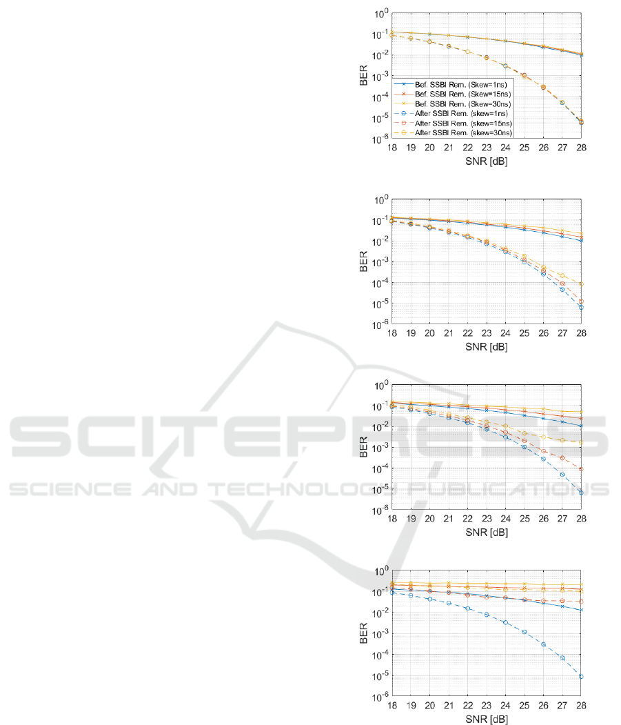
Figure 8 shows the BER before and after SSBI re-
moval as a function of the SNR with P
r
= 18 dB, for
different skew values and for the laser linewidths in-
dicated in Table 1.
Figure 8 (a) shows that, for a laser linewidth of
100 kHz, the impact of the skew on the system per-
formance is negligible. By analysing the t
c
(see Table
1) obtained for a 100 kHz linewidth, it can be seen that
the coherence time is much higher than the skew val-
ues under test (approximately 100 times higher than
30 ns). So, the skew effect on the phase-to-intensity
noise conversion is low. Figure 8 (a) enables also to
conclude that for the 100 kHz laser linewidth, a BER
Short-reach 200 Gb/s SDM Network Employing Direct-detection and Optical SSBI Mitigation
127
of 10
−3
is reached for all skew values considered, for
a SNR of 25 dB, when SSBI mitigation is employed.
When increasing the laser linewidth and thus de-
creasing the respective t
c
, the system performance be-
comes more sensitive to the skew. As it can be seen
in Figure 8 (b) (linewidth of 500 kHz), the curves cor-
responding to the SSBI removal results start to show
the effect of the laser phase noise. When increasing
the skew, it can be seen that the BER starts to increase
as well. Still, the coherence time corresponding to the
500 kHz linewidth is 21 times higher than the longest
skew considered. So, although the effects are felt,
they are not excessively degrading the system perfor-
mance. For this laser linewidth, a SNR of at least 26
dB guarantees a BER lower than 10
−3
for all skew
values tested.
Figure 8 (c) shows that the skew effect on the
phase-to-intensity noise conversion starts to become
significant for a linewidth of 1 MHz, degrading the
system performance. For a skew of 30 ns, the coher-
ence time corresponding to 1 MHz laser linewidth is
only 10 times longer than the skew. So, it is expected
(and proven by the results), that the degradation due
to the phase noise severely impacts the system. For
a skew of 30 ns, it is not possible to reach a BER
lower than 10
−3
after SSBI mitigation. In contrast,
the laser linewidth of 1 MHz can provide a BER lower
than 10
−3
after SSBI removal, for SNR values of or
above 26 dB, up to a skew of 15 ns. It is worth noting
that for a skew of 15 ns, the results are identical to
the results obtained for a skew of 30 ns and the 500
kHz linewidth. For both these cases, the relation be-
tween the skew and the laser’s coherence time is the
same, being the coherence time 21 times higher than
the skew.
Figure 8 (d) shows the BER results for a laser
linewidth of 5 MHz. Results of Figure 8 (d) show that
the 5 MHz linewidth has very low tolerance to the
increasing skew values. For the results presented in
Figure 8 (d), the benefits of employing the proposed
SSBI mitigation approach occur only for a skew of 1
ns. For 15 and 30 ns skew, the SSBI mitigation tech-
nique is not effective due to high levels of phase-to-
intensity noise conversion. Bearing in mind the co-
herence time corresponding to 5 MHz linewidth, and
taking into account the results described throughout
this subsection, it is possible to deduce that a laser
with a linewidth of 5 MHz only tolerates a degrada-
tion caused by phase-to-intensity noise conversion for
a maximum skew of 3 ns. In this case, the coher-
ence time corresponding to the 5 MHz linewidth is 21
times higher than the 3 ns skew, which, as seen be-
fore, guarantees a BER under 10
−3
for SNR values
exceeding 25 dB.
(a)
(b)
(c)
(d)
Figure 8: BER as a function of the SNR before (continuous
line) and after (dashed line) SSBI removal considering dif-
ferent skew values, for a laser linewidth of: (a) 100 kHz, (b)
500 kHz, (c) 1 MHz and (d) 5 MHz.
4.4 Dispersion Impact on the System
Performance
In this subsection, the impact of the chromatic disper-
sion on the system performance is evaluated, in the
PHOTOPTICS 2021 - 9th International Conference on Photonics, Optics and Laser Technology
128
presence of skew and laser phase noise. From the
study of subsection 4.3, the SNR values required for a
BER lower than 10
−3
were identified. So, this study is
performed for a SNR of 26, 27 and 28 dB; for lower
SNR values, the BER after SSBI removal is higher
than 10
−3
, showing no interest for the scenarios un-
der evaluation. The laser linewidths chosen for this
study are 100 kHz and 5 MHz.
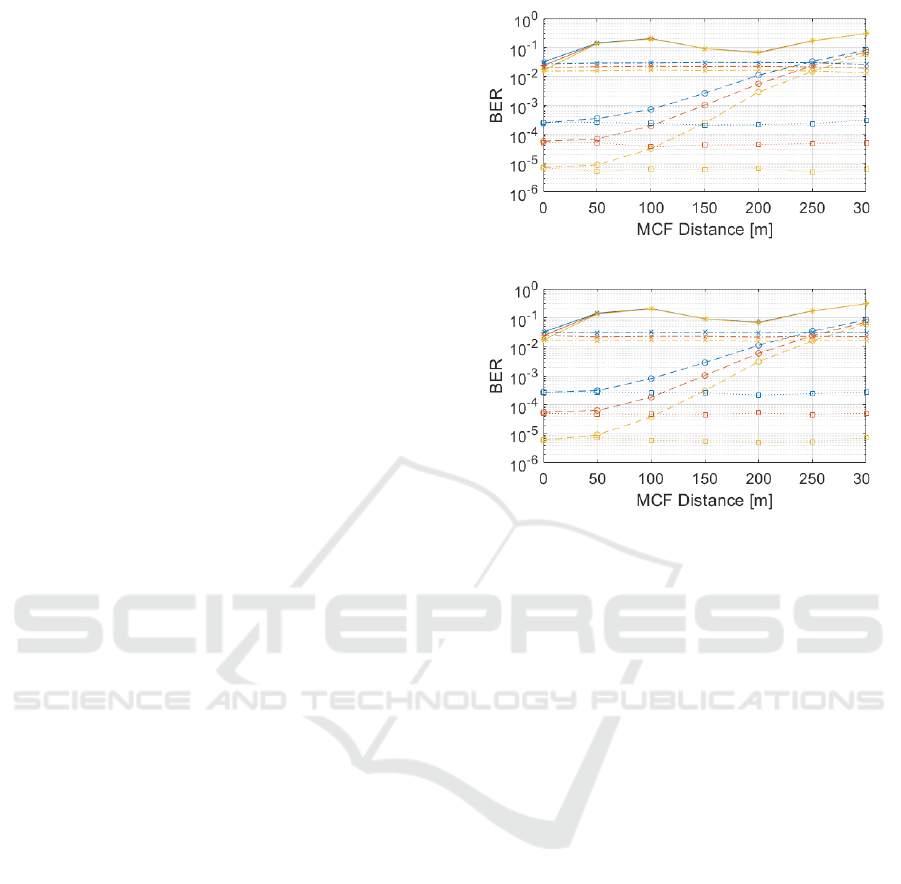
Figure 9 demonstrates the dispersion and skew im-
pact on the BER. Each set of curves are composed by
3 lines, which represents a SNR of 26 dB (higher BER
of each set), 27 dB and 28 dB (lowest BER of each
set). The results were obtained in the following con-
ditions: before SSBI removal with dispersion (con-
tinuous line) and without dispersion (dashed and dot-
ted line); after SSBI removal with dispersion (dashed
line) and without dispersion (dotted line), in order to
evaluate how differently each impairment impacts the
system. A walk-off of 10 ns/20 km was considered.
Figure 9 (a) shows the BER as a function of the
MCF length for a laser linewidth of 100 kHz. Com-
paring with Figure 9 (b), which shows the 5 MHz
linewidth results, it is possible to conclude that very
similar results are obtained. In presence of disper-
sion, both linewidths surpass a BER of 10
−3
for fi-
bre lengths longer than 180 m after SSBI removal
for the most favorable case (SNR of 28 dB). In con-
trast, the results that emulate an ideally compensated
dispersion environment (dotted and dashed and dot-
ted lines - null total dispersion) show that the BER
remains practically unchanged for the tested length.
Under these conditions, the phase-to-intensity noise
conversion is the only effect impacting the system
performance, and the results in Figure 9 (a) and (b)
show that, for the tested walk-off and fibre lengths,
the system performance is weakly affected, regardless
the analysed laser linewidth. As an example, for 300
m of MCF length, we have a skew of 0.15 ns, which,
as has been shown in subsection 4.3, is not enough
to degrade the system performance due to phase-to-
intensity noise conversion. These results show that,
in presence of dispersion, the results before and after
employing SSBI mitigation rapidly converge, as the
fibre chromatic dispersion significantly degrades the
system performance. However, when the dispersion is
compensated, promising results can be achieved when
SSBI removal is performed. In order to compensate
for the dispersion, the SSBI component needs to be
suppressed. This can successfully occur when a high
P
r
is used, since a BER performance improvement be-
fore and after SSBI removal is only achieved under
those conditions.
Figure 9 results help to emulate a real-use sce-
nario, where dispersion and walk-off are inherent ef-
(a)
(b)
Figure 9: BER as a function of the MCF length, before
SSBI removal with dispersion (continuous line) and without
dispersion (dashed and dotted line), and after SSBI removal
with dispersion (dashed line) and without dispersion (dotted
line), for a laser linewidth of: (a) 100 kHz and (b) 5 MHz.
fects of the fibre. When dispersion compensation is
not employed, the maximum link length reached is
between 100 and 180 m (for the considered SNR val-
ues), hence being suitable for intra DC connections.
Longer connections may be achieved, reaching inter
DC lengths, by utilising dispersion mitigation tech-
niques. However, that study is out of the scope of this
work.
5 CONCLUSIONS
An innovative transmission scheme has been pro-
posed, where the 200 Gb/s NRZ signal and the vir-
tual carrier are transmitted in separate cores of a MCF,
targeting a low complexity SSBI mitigation approach
at the RX side to improve the system performance
of short-reach MCF-based networks employing DD
receivers. It has been shown that the combined ef-
fect of the skew and the laser phase noise affects the
signal quality. Systems employing lasers with higher
linewidths become more sensitive to the skew, limit-
ing further the system performance due to phase-to-
intensity conversion. It has been also shown that the
proposed SSBI mitigation technique is effective only
Short-reach 200 Gb/s SDM Network Employing Direct-detection and Optical SSBI Mitigation
129

when a high P
r
is considered, and for a low electrical
noise environment.
For systems not impaired by the dispersion, a BER
improvement (to values lower than 10
−3
) after SSBI
removal is obtained, for a P
r
of 18 dB and a skew of
1 ns, and for a laser linewidth up to 5 MHz. Also, a
BER lower than 10
−3
is achieved for a skew up to 15
ns and a laser linewidth of 1 MHz. It has been shown
that the dispersion rapidly degrades the received sig-
nal quality, exceeding a BER of 10
−3
for a MCF
length longer than approximately 180 m. The re-
sults indicate that, in absence of dispersion compensa-
tion, the proposed transmission scheme show poten-
tial to be employed in intra DC connections. Never-
theless, the higher potential of the proposed transmis-
sion technique is achieved for systems in which the
dispersion effect is compensated electronically at the
RX side. For systems with full dispersion compensa-
tions, the results show a significant performance im-
provement achieved by the SSBI mitigation approach
employed, showing great interest for high capacity
short-reach SDM networks.
ACKNOWLEDGEMENTS
This work was partially funded by FCT/MCTES
through national funds and when applica-
ble co-funded EU funds under the project
UIDB/EEA/50008/2020 and project Dig-
Core/UIDP/50008/2020.
REFERENCES
Butler, D. L., Li, M.-J., Li, S., Geng, Y., Khrapko, R.,
Modavis, R. A., Nazarov, V., and Koklyushkin, A.
(2017). Space division multiplexing in short reach op-
tical interconnects. Journal of Lightwave Technology,
35:677–682.
Cartledge, J. C. and Karar, A. S. (2014). 100 Gb/s intensity
modulation and direct detection. J. Lightwave Tech-
nol., 32(16):2809–2814.
Cisco (2018). Cisco global cloud index: forecast and
methodology, 2016–2021. White paper, pages 1–46.
Goodman, J. (2015). Statistical Optics. Wiley Series in
Pure and Applied Optics. Wiley.
Hayashi, T., Nagashima, T., Morishima, T., Saito, Y.,
and Nakanishi, T. (2019). Multi-core fibers for
data center applications. In 45th European Con-
ference on Optical Communication (ECOC 2019).
DOI: 10.1049/cp.2019.0754
Ishimura, S., Kao, H., Tanaka, K., Nishimura, K., and
Suzuki, M. (2019). Ssbi-free 1024qam single-
sideband direct-detection transmission using phase
modulation for high-quality analog mobile fronthaul.
In 45th European Conference on Optical Communica-
tion (ECOC 2019). DOI: 10.1049/cp.2019.1016
Ju, C., Liu, N., and Chen, X. (2015). Comparison of it-
eration interference cancellation and symbol predis-
tortion algorithm for direct detection orthogonal fre-
quency division multiplexing passive optical network.
Optical Engineering, 54(8).
Kachris, C. and Tomkos, I. (2012). A survey on optical
interconnects for data centers. IEEE Communications
Surveys Tutorials, 14(4):1021–1036.
Nezamalhosseini, S. A., Chen, L. R., Zhuge, Q., Malek-
iha, M., Marvasti, F., and Plant, D. V. (2013). Theo-
retical and experimental investigation of direct detec-
tion optical ofdm transmission using beat interference
cancellation receiver. Optics Express, 21(13):15237–
15246.
Peng, W. (2010). Analysis of laser phase noise effect in
direct-detection optical ofdm transmission. Journal of
Lightwave Technology, 28(17):2526–2536.
Puttnam, B., Lu
´
ıs, R., Klaus, W., Sakaguchi, J., Mendin-
ueta, J. D., Awaji, Y., Wada, N., Tamura, Y., Hayashi,
T., Hirano, M., and Marciante, J. (2015). 2.15 pb/s
transmission using a 22 core homogeneous single-
mode multi-core fiber and wideband optical comb. In
2015 European Conference on Optical Communica-
tion (ECOC). DOI: 10.1109/ECOC.2015.7341685
Soma, D., Igarashi, K., Wakayama, Y., Takeshima, K.,
Kawaguchi, Y., Yoshikane, N., Tsuritani, T., Morita,
I., and Suzuki, M. (2015). 2.05 peta-bit/s super-
nyquist-wdm sdm transmission using 9.8-km 6-mode
19-core fiber in full c band. In 2015 Euro-
pean Conference on Optical Communication (ECOC).
DOI: 10.1109/ECOC.2015.7341686
PHOTOPTICS 2021 - 9th International Conference on Photonics, Optics and Laser Technology
130
