
Integrating a Head-mounted Display with a Mobile Device for Real-time
Augmented Reality Purposes
Bruno Madeira
1 a
, Pedro Alves
1 b
, Anabela Marto
2,3 c
, Nuno Rodrigues
2 d
and Alexandrino Gonc¸alves
2 e
1
ESTG, Polytechnic of Leiria, Morro do Lena, Leiria, Portugal
2
CIIC, ESTG, Polytechnic of Leiria, Morro do Lena, Leiria, Portugal
3
INESCT TEC, Rua Dr. Roberto Frias, Porto, Portugal
Keywords:
Augmented Reality Glasses, Mobile Devices, SIMD, Display Calibration, Industry 4.0.
Abstract:
Following the current technological growth and subsequent needs felt by industries, new processes should be
adopted to make tasks simpler. Using Augmented Reality in conjunction with other technologies, it is pos-
sible to develop innovative solutions that aim to alleviate the difficulty of certain processes in the industry,
or to reduce the time of their execution. This article addresses one of the possible applications of new tech-
nologies in the industry, using devices that allow the use of Augmented Reality without requiring much or
no physical interaction by workers or causing many distractions, thus giving relevant information to the work
to be performed without interfering with the quality of it. It will focus, more precisely, on integrating the
Head-Mounted Display Moverio BT-35E with a mobile device and in describing the needed configurations for
preparing this device to show information to warehouse operators, using Augmented Reality, provided by a
software that runs on a capable device, discussing also what are the main mishaps discovered with the use of
this device.
1 INTRODUCTION
With the growth in the industry and its processes, it is
necessary to combine new technology developments
to make certain processes faster and more agile. One
of the new emerging technologies that can enhance
industry processes is Augmented Reality (AR). AR is
a way of viewing an enhanced version of the physical
real-world with over imposed virtual artifacts gener-
ated by a processing unit. Using it in the industry
enables tasks like order picking in a warehouse to be-
come much simpler to the operator, with the availabil-
ity of virtual information about the user’s surround-
ings and information about tasks to do, enhancing his
perception and interaction (Julie Carmigniani, 2010).
There are different options where to run and/or
present AR applications, for example, Smartphones,
Tablets, and Head-Mounted Displays (HMD), mak-
a
https://orcid.org/0000-0001-7991-9607
b
https://orcid.org/0000-0002-3869-6125
c
https://orcid.org/0000-0001-6005-288X
d
https://orcid.org/0000-0002-0953-6018
e
https://orcid.org/0000-0002-5966-3218
ing difficult the process to choose one since it has to
be kept in mind if the chosen device supports process-
ing data or if it needs a parallel device to do the com-
puting, or even if it suits the case. In our case, the
need for a device with minimal or no interaction with
the user was the perfect solution. In this paper, is de-
scribed how an HMD device, the Moverio BT- 35E,
can be configured so that it can be used for AR pur-
poses.
The device is meant to be used in a project cur-
rently under development, named ARWare. The
project aims to develop software for companies to im-
prove their organization, management, and the effi-
ciency of logistics and picking operations in ware-
houses. The software includes technologies and
methodologies such as the Internet of Things (IoT),
Industry 4.0, AR, 2D/3D Mapping, image processing,
and the use of intelligent algorithms – based on Arti-
ficial Intelligence (AI) – to achieve a quick and more
optimized route for operators to pick the objects.
By using this software, it is intended that daily op-
erations in warehouses would become easier for the
operator’s and can be performed more efficiently, with
the combination of all logistics information that is
Madeira, B., Alves, P., Marto, A., Rodrigues, N. and Gonçalves, A.
Integrating a Head-mounted Display with a Mobile Device for Real-time Augmented Reality Purposes.
DOI: 10.5220/0010338703130319
In Proceedings of the 16th International Joint Conference on Computer Vision, Imaging and Computer Graphics Theory and Applications (VISIGRAPP 2021) - Volume 1: GRAPP, pages
313-319
ISBN: 978-989-758-488-6
Copyright
c
2021 by SCITEPRESS – Science and Technology Publications, Lda. All rights reserved
313
stored and available in the ERP/WMS (Enterprise Re-
source Planning/Warehouse Management Systems)
systems, the use of AR, precise indoor location and
intelligent route optimization using AI algorithms.
Combining all this information and technologies,
contextual information related to the action that the
operator is performing at that moment should be trig-
gered. Its compatibility with AR technology is tar-
geted for reducing the possibility of errors from the
operator, optimizing operations’ efficiency.
This paper will be important to the research com-
munity due to the lack of documentation and details
in this matter and due to the use and development of
all the innovative technologies and processes involved
in the overall solution.
2 STATE OF THE ART
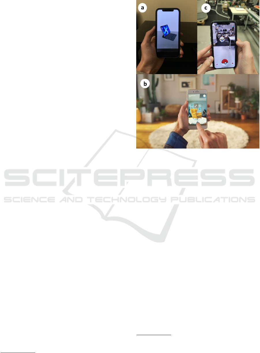
Nowadays AR is becoming a widely adopted tech-
nology especially for advertisement, commercial pur-
poses, and gaming. As an example, Apple offers an
AR view of almost all of its products so that cus-
tomers can be aware of the size and how the product
looks. To be able to see the product in AR, the users
must visit the product page of the item in a smart-
phone or tablet and look for the icon to show in AR,
then, find a surface and the object will be placed, as
illustrated in Figure 1a.
Ikea, the Swedish furniture retailer, developed an
App, called IKEA Place, where it enables users to get
a glimpse about how a product would look in their
homes with 98% accuracy of the size of the item,
since the app scales the item based on the size of
the user’s room (Ozturkcan, 2020).This way, shoppers
can be more confident about what they are buying and
if it will fit their needs and taste. An example of this
can be seen in Figure 1b.
The mobile gaming industry is also adopting AR
technology to enhance their games experience to the
users. One great example of that is the widely known
game Pok
´
emon Go
1
developed by Niantic. The game
uses AR to let users catch or play with Pok
´
emons that
can be placed virtually in the world as illustrated in
Figure 1c.
Besides these areas, the industry is another area
that is starting to use AR technologies to help im-
prove and simplify some of their tasks and workflow.
One example of this is the use of AR software that
gives aid to operators on how to fix, maintain or even
get help from the owner’s manual regarding machines
that they operate (Aleksy et al., 2014). Using AR,
1
https://pokemongolive.com/en/
Figure 1: Different AR applications. (a) Apple iPad showed
in AR. (b) Ikea Place APP
2
. (c) Pok
´
emon Go.
operators can get a more interactive view of the in-
formation regarding a task and also use this technol-
ogy to get help from another worker or assistant on-
line and without the need to schedule an appointment
on the local. Processes like these are possible by the
use of TeamViewer Pilot
3
, for example, an AR ap-
proach of this remote access software (Riccardo Ma-
sonia, 2017) also presented an application for industry
products maintenance purposes.
Another example of the use of AR in industries
is the order picking process in warehouses. Tradi-
tionally, the process of order picking in warehouses
has been made using paper lists, without any or much
technology support. Nowadays, most warehouses re-
sort to the use of new technologies to help speed up
and make more practical all the order picking pro-
cess in the logistical process. These technologies can
range from mobile terminals with built-in scanners so
that the operator can scan bar codes, to pick by light
or pick by voice systems (Reif et al., 2010). Taking
this into consideration, adopting the use of AR for this
purpose, as shown by (Schwerdtfeger and Klinker,
2008), where a software was developed to use with an
HMD device to help this process, can help workers to
2
https://www.ikea.com/au/en/customer-service/
mobile-apps/say-hej-to-ikea-place-pub1f8af050
3
https://www.teamviewer.com/en-us/
augmented-reality/
GRAPP 2021 - 16th International Conference on Computer Graphics Theory and Applications
314
be more productive in their tasks. Similar implemen-
tations with the same purpose of helping warehouse
order picking processes and using HMD’s where also
presented by Ubimax
4
in partnership with DHL
5
and
another solution presented by SAP
6
.
3 AR IMPLEMENTATION
3.1 ARWare Project
The ARWare project is being developed by multiple
teams and involving various technologies. These are
distributed in smaller pieces of software/applications
that will integrate with the overall solution, such as:
Route Planning software, ERP (to manage all the data
and information of the enterprise), Approximate Lo-
cation software, Indoor Fine Location Application,
and AR Application. All these components com-
municate with each other using an Enterprise Ser-
vice Bus (ESB) from Microsoft Azure with the use
of Topics (Publish/Subscribe) and also Services (Re-
quest/Response) or in the case of the communication
between the AR and Indoor Fine Location Applica-
tions, with the use of UDP Sockets. The architecture
of the overall software solution can be observed in
Figure 2.
Figure 2: General Software Architecture.
In the following subsections of this chapter, the
information will be focused on the AR component of
this software, mostly in the calibration process and
usage of the chosen AR glasses, the Moverio BT-35E
by Epson, also described latter.
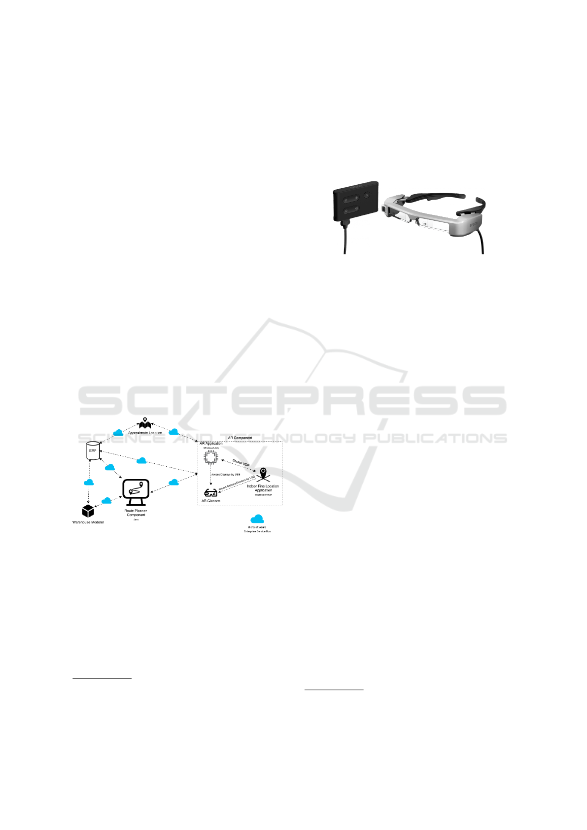
3.2 Hardware
The Moverio BT-35E is a binocular Optical See-
through device that can be used for AR approaches.
4
https://www.ubimax.com/
5
https://www.youtube.com/watch?v=I8vYrAUb0BQ
6
https://www.youtube.com/watch?v=OrYHJaSAxis
The device, illustrated in Figure 3, has a camera
and multiple sensors. However, it does not have pro-
cessing capabilities required for AR applications and
only works as an input or output device. To run any
software, an external device that handles the process-
ing must be used, such as a computer or a mobile
phone.
Figure 3: Moverio BT-35E.
Despite the device’s hardware AR capabilities, it
was not found any AR Software Development Kits
(SDKs) that support the device before the date of this
writing. There are two types of SDK’s: the BT- 35E’s
SDK which allows accessing the camera, and sen-
sors data; and there are AR SDKs, such as Wikitude,
Maxst, and EasyAR, that can receive image data from
an arbitrary source and can, therefore, be integrated
with the device. However, none of these SDKs can
process images in the RGB565 format, which is used
by the BT-35E SDK, and none allow, at least for free,
to calibrate the device’s displays which are needed to
use spatially aware augmentation.
This document presents an integration of the BT-
35E with the Huawei P20 mobile device, which en-
tails the implementation of display calibration using
Open Computer Vision library (OpenCV) aruco mod-
ule and image conversion via hardware-specific in-
structions. The mentioned functionalities were inte-
grated with the Unity game engine.
3.2.1 Rendering
BT-35E display technology can be classified as con-
ventional stereoscopic 3D, using the taxonomy in
(Zabels et al., 2019, p. 6).
The device allows projecting a 2D video source
at a fixed, unspecified
7
, vergence distance. Alterna-
tively, it has a 3D mode that splits the source in half
and displays each half entirely in each of the displays.
Both modes can be observed in Figure 4.
This means that the rendering content for the BT-
35E’s displays can be done in the same way that it is
done for any 2D screen.
Rendering stereoscopic content can be achieved
by drawing to each half of the display using virtual
7
Supposing it is the same as the default on previous
models, the vergence distance is around 11 meters.
Integrating a Head-mounted Display with a Mobile Device for Real-time Augmented Reality Purposes
315
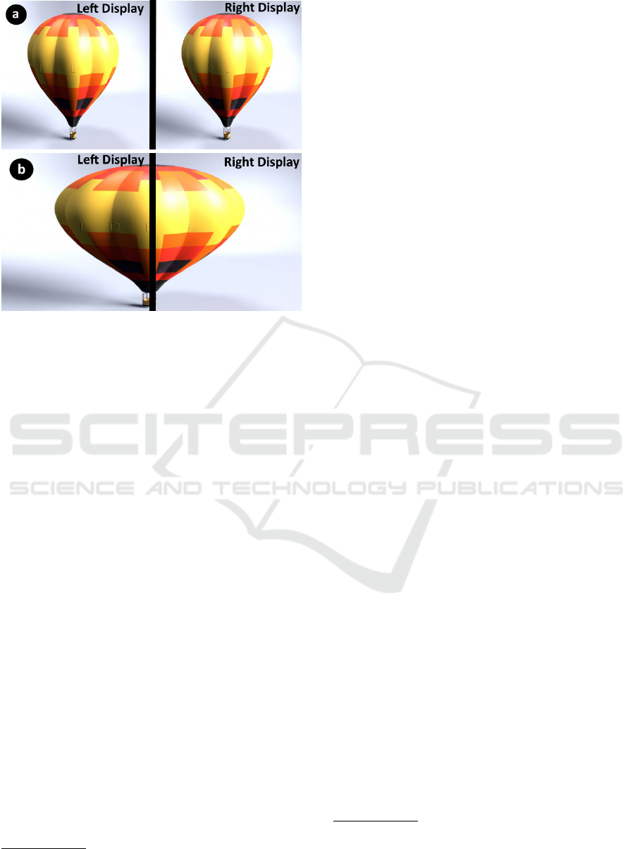
Figure 4: BT-35E display modes. (a) 2D mode. (b) 3D
mode.
cameras that model the projection of the correspond-
ing eye.
3.3 Image Format Conversion
The RGB565 is a pixel color format that describes an
image in red, green, and blue color components. The
format is very similar to the RGB24 format, which
contains 8 bits per pixel color channel, but RGB565
discards the 3 least significant bits of the red and blue
components, and 2 bits of the green component.
Since this format is not supported by OpenCV, the
source image used by the BT35-E SDK needs to be
converted. Additionally, the conversion process needs
to be efficient to achieve a stable frame rate, minimize
the latency of AR-related updates, and avoid thermal
throttling.
In (Wagner and Schmalstieg, 2007), this conver-
sion is done using lookup tables into the LUM8 for-
mat; an advantage of this approach is that it is agnostic
to hardware.
Unlike the above-presented method, our imple-
mentation relies on hardware capabilities. It borrows
ideas from the libYUV library
8
, and implements im-
age conversion in assembly for the NEON64 SIMD.
GPU based conversion was also implemented prior to
the SIMD solution.
8
An image format conversion library optimized for
SIMD architectures (Google Inc., 2020).
3.3.1 GPU
GPU based conversion was seen as the easiest solu-
tion to integrate due to the following reasons:
• Unity, the target development platform, has built-
in tools to implement, compile, and use compute
shaders. Dissimilarly, a SIMD-based solution re-
quires the implementation of a plugin;
• The conversion to the RGBA32 format using
High-Level Shader Language (HLSL) is trivial to
implement;
• An HLSL implementation is agnostic to graph-
ics API; and is, therefore, more portable than
architecture-specific assembly implementations.
It was first implemented image conversion for the
color format RGBA32, which resulted in near 30
conversions per second with an image resolution of
1280x720 pixels when tested in isolation, i.e., with-
out using a AR module.
The above results show that GPU-based image
conversion may be enough for some applications;
however, they are not conclusive regarding real-time
AR applications. To determine whether it was a vi-
able solution when using real-time AR, the same test
was done using Maxst SDK 4.x marker detection over
the converted image. Note that camera or display cal-
ibration was not required to test performance. When
using the Maxst SDK the performance fell to around
12 to 16 conversions per second, and the device would
heat up considerably.
It was noticed that changing graphics API affected
performance; the default API, OpenGLES3 API, had
better performance than Vulkan.
We also implemented image conversion to a single
channel grey image, and RGB24
9
color formats. Both
formats can be used with OpenCV; however, none im-
proved the performance of the image conversion pro-
cess significantly.
The OpenCV aruco module had worse perfor-
mance than the Maxst SDK; which meant that our
GPU-based image conversion implementation was
not suited for manual display calibration, and there-
fore, not suited for real-time AR either.
3.3.2 SIMD
To try to achieve better results it was implemented
image conversion to the color formats RGBA32 and
RGB24. This approach outperformed the GPU so-
9
The RGB24 format, due to the limitations of the data
types available in compute shaders, does not allow a stream-
lined conversion; it requires the addition of an unused mar-
gin.
GRAPP 2021 - 16th International Conference on Computer Graphics Theory and Applications
316
lutions, allowing a maximum conversion rate of near
60 frames per second (fps) using the same resolution;
however, prolonged use would cause it to heat up and
drop performance.
We obtained a conversion rate of approximately
30 and 19 fps using the Maxst SDK and OpenCV re-
spectively, at a resolution of 1280x720 pixels.
Although results were below 30 fps, below the dis-
play refresh rate, they were good enough for calibra-
tion purposes, although not ideal. When calibrating
the device, to ensure a stable frame rate, and avoid
heating the device, we locked the rate of image out-
puts by the BT-35E SDK at a frequency of 15 fps.
3.4 Display Calibration
Via a display calibration method, the eyes’ projection
matrices are estimated. This calibration can be clas-
sified, according to (Grubert et al., 2018), as follows:
manual, requiring user interaction; automatic, done
without user intervention; or semi-automatic by re-
ducing user inputs thought some automatic process
typically done apriori. The methods we implemented
fall under the family of manual calibration methods.
3.4.1 SPAAM
The first implemented display calibration method was
the Single Point Active Alignment Method (SPAAM)
(Tuceryan et al., 2002). Since SPAAM requires no
additional hardware since it is a manual method, and
because it is well documented, being that the origi-
nal paper shows the required steps to integrate it with
Open Graphics Library (openGL), it was a prime can-
didate as a first display calibration method implemen-
tation.
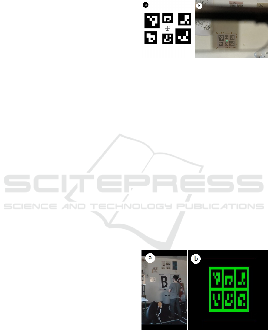
Our implementation uses a board with 6 ArUco
markers. The center of the board is marked with a
cross-hair image that indicates the world point that
the user needs to align with the on-screen displayed
points, as illustrated in Figure 5b. To present 3D
content that respects real-world coordinates, not nec-
essarily displayed over ArUco markers only, camera
calibration was done before the display calibration us-
ing a ChArUco board.
With the results presented in (Axholt et al., 2011)
as a reference point, the number of points per display
to align in our implementation was set to 25. No par-
ticular point distribution was used, but it was taken
into account that there should be variation in points
depth.
Regarding the efficiency of the calibration pro-
cess, (Wagner and Schmalstieg, 2007) compares the
time that different, but similar, calibration methods
take, and SPAAM shows the worst results. With this
Figure 5: SPAAM calibration procedure. (a) Board where
to align the cross-hair during calibration; (b) Example of
what is seen through one of the device’s display during the
calibration process.
in mind and having experienced the cumbersome pro-
cess of the SPAAM calibration, an additional calibra-
tion method was conceptualized and implemented.
3.4.2 FABSAM
Fixed Axis Bi-dimensional Shape Alignment Method
(FABSAM), is the novel term here presented, to de-
note a manual calibration method in which the user
aligns a shape along a fixed axis, at different depths.
FABSAM is a hybrid between the depth-SPAAM
and MPAAM calibration methods described in (Tang
et al., 2003) and (Grubert et al., 2020) respectively.
Similar to MPAAM, the user has to align a group of
points, but these are not distributed at different depths.
Then, similarly to depth-SPAAM, the user needs to
repeat the previous procedure at different depths. In-
stead of being made aware of the points to align, the
user is presented with a shape that is displayed at dif-
ferent sizes, which in our implementation is a board
composed of aruco markers, depicted in Figure 6b.
The points to be matched are within the shape and are
set via the Unity editor.
Figure 6: FABSAM calibration procedure. (a) User align-
ing the displayed board with the board on the wall. (b) Im-
age of the calibration board shown on the left display of
the AR glasses, horizontally shrink-ed due to display stream
setup.
Integrating a Head-mounted Display with a Mobile Device for Real-time Augmented Reality Purposes
317
The conceptualization of this method was rooted
in the following assumptions:
1. Calibration point depth distribution is more im-
portant than alignment noise.
The method enforces depth distribution by pre-
senting an image at different sizes, which forces
the user to change their distance to the target.
Note that BT-35E’s camera direction is approxi-
mately aligned with the user’s orientation when
facing the board so that the camera distance to the
board is like the user distance to the board. This
assumption is rooted in the findings presented in
(Axholt et al., 2011) and (Moser et al., 2014).
2. Display curvature is negligible. In the case of the
BT-35E, this is applicable because the displays are
plane by their small size and field of view.
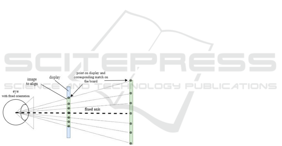
3. Eye orientation changes are negligible.
Because the user aligns a shape instead of a sin-
gle point, we suppose the eye orientation remains
fixed as depicted in Figure 7; however, we do not
have any data to back up this assumption.
The calibration procedure is assistance free: it
does not use a device to mitigate user shakiness
or enforce correct alignment at different depths;
thus, it may not be negligible regarding eye orien-
tation, unlike supposed.
Figure 7: Fixed Axis Bi-dimensional Shape Alignment
Method.
Note that both SPAAM and FABSAM only need
to know the position of the target points to align to the
camera coordinate system, and, despite what our im-
plementations might suggest, there is no need to have
a target point superimposed over an aruco marker or
board. The main utility of being superimposed is that
it is portable, however, this is not a requirement. The
markers are not a requirement either if the target po-
sition can be known through a different method. Al-
though not tested, it is plausible that having an en-
vironment covered in markers, not necessarily aruco
or id-based markers, would allow estimating the tar-
get points position with higher accuracy, thus result-
ing in a better calibration. Such consideration led to
the conceptualization of an alternate FABSAM cali-
bration protocol in which the target height is adjusted
to the user’s eyes height and used as input to grasp its
position to non-superimposed markers on the calibra-
tion environment.
4 DISCUSSION
In sections 3.3.2 and 3.4.2, we presented a minimum
viable solution for AR SDKs integration and display
calibration. The presented solution performance is,
however, not ideal, running at a lower frequency than
the minimum display refresh rate supported by the
BT-35E displays, 30 fps.
A possible improvement regarding the perfor-
mance limitations of our solution is to improve data
workflow by, for example: converting the image di-
rectly into a single channel instead of 3 RGB channels
which are converted by OpenCV aruco module into
one subsequently; replace OpenCV operations with
ARM Compute Library (ACL) such as threshold; im-
proving data locality if possible. An alternate solution
might be to use the Neural Processing Unit (NPU) of
the mobile device to detect the aruco markers. (Hu
et al., 2018) has implemented a neural network-based
solution that outperforms traditional marker detection
for ChArUco boards. Although, we are not knowl-
edgeable enough to comment on whether this ap-
proach is viable or not for the target hardware.
The calibration methods yielded acceptable qual-
itative results, but no data was collected or analyzed
to make a rigorous evaluation. In our calibration at-
tempts, FABSAM topically took less time to cali-
brate. Additionally, was noticed that SPAAM would
sometimes result in bad calibration due to bad aligned
points, which did not happen when calibrating with
FABSAM.
Regarding the details of the FABSAM, in our im-
plementation, the points to match are contained in-
side the shape to align. An alternate implementation
could consider points outside of the shape to align, so
that point distribution is not higher towards the center.
This could impact the calibration quality.
5 CONCLUSION AND FUTURE
WORK
This paper describes the utilization of AR technol-
ogy with a focus on industry applications, more pre-
cisely the use in warehouses. It is presented which
GRAPP 2021 - 16th International Conference on Computer Graphics Theory and Applications
318

factors should be taken into consideration when using
the Moverio BT-35E binocular Optical See-Through
device. Although somewhat capable, this device is
not the best suited for AR purposes, due to the lack
of specific System Development Kits for their setup
and usage. That said, this paper focus on techniques
and procedures on how to get this device setup for AR
usage, trying to circumvent the mishaps that currently
exist.
Some obstacles were raised during the develop-
ment, like the lack of System Development Kits that
provide device display calibration for free and/or
weren’t fully compatible with each other. This cre-
ated the need for developing a solution for that, where
performance was also an obstacle to take into account
and discussed in the paper.
In the future it is expected that the concepts and
processes discussed here in this article will be applied
in the project under development, more precisely us-
ing the device with an AR software in support for
warehouse order picking processes. This way, it is
possible to help a warehouse operator to perform his
tasks in a simpler and faster way, without great com-
plexity or previous knowledge required. This aid may
be provided using the information and visual instruc-
tions on the Epson BT-35E device, thus informing the
user of the current status of a task, which must be
taken inside a warehouse when executing a route con-
sisting in the picking of products, among others.
ACKNOWLEDGMENTS
This work is co-financed by the ERDF - European Re-
gional Development Fund under the Operational Pro-
gram for Competitiveness and Internationalization -
COMPETE 2020 of Portugal 2020 through ANI - Na-
tional Innovation Agency - Project ”AR WARE: Aug-
mented Reality for intelligent WAREhouse manage-
ment: POCI- 01-0247-FEDER-033432”.
REFERENCES
Aleksy, M., Vartiainen, E., Domova, V., and Naedele, M.
(2014). Augmented reality for improved service deliv-
ery. In 2014 IEEE 28th International Conference on
Advanced Information Networking and Applications,
pages 382–389.
Axholt, M., Cooper, M. D., Skoglund, M. A., Ellis, S. R.,
O’Connell, S. D., and Ynnerman, A. (2011). Parame-
ter estimation variance of the single point active align-
ment method in optical see-through head mounted dis-
play calibration. In 2011 IEEE Virtual Reality Confer-
ence, pages 27–34.
Google Inc. (2020). libYUV readme. https:
//chromium.googlesource.com/libyuv/libyuv/+/refs/
heads/master/README.md. Accessed: 2020-10-02.
Grubert, J., Itoh, Y., Moser, K., and Swan, J. E. (2018). A
survey of calibration methods for optical see-through
head-mounted displays. IEEE Transactions on Visu-
alization and Computer Graphics, 24(9):2649–2662.
Grubert, J., T
¨
umler, J., and Mecke, R. (2020). Optimierung
der see-through-kalibrierung f
¨
ur mobile augmented-
reality-assistenzsysteme. Fraunhofer IFF.
Hu, D., DeTone, D., Chauhan, V., Spivak, I., and Mal-
isiewicz, T. (2018). Deep charuco: Dark charuco
marker pose estimation.
Julie Carmigniani, Borko Furht, M. A. P. C. E. D. M. I.
(2010). Augmented reality technologies, systems and
applications. Multimedia Tools and Applications, 51.
Moser, K., Axholt, M., and Swan, J. (2014). Baseline spaam
calibration accuracy and precision in the absence of
human postural sway error. pages 99–100.
Ozturkcan, S. (2020). Service innovation: Using augmented
reality in the ikea place app. Journal of Information
Technology Teaching Cases.
Reif, R., G
¨
unthner, W. A., Schwerdtfeger, B., and Klinker,
G. (2010). Evaluation of an augmented reality sup-
ported picking system under practical conditions.
Computer Graphics Forum, 29(1):2–12.
Riccardo Masonia, Francesco Ferriseb, M. B. M. G. A. E.
U. M. F. E. C. M. D. D. (2017). Supporting remote
maintenance in industry 4.0 through augmented re-
ality. In Marcello Pellicciari, M. P., editor, Proce-
dia Manufacturing Volume 11, 2017, 27th Interna-
tional Conference on Flexible Automation and Intel-
ligent Manufacturing, FAIM2017, pages 1296–1302.
Procedia Manufactering.
Schwerdtfeger, B. and Klinker, G. (2008). Supporting
order picking with augmented reality. In 2008 7th
IEEE/ACM International Symposium on Mixed and
Augmented Reality, pages 91–94.
Tang, A., Zhou, J., and Owen, C. (2003). Evaluation of
calibration procedures for optical see-through head-
mounted displays. pages 161–168.
Tuceryan, M., Genc, Y., and Navab, N. (2002). Single-
point active alignment method (spaam) for optical
see-through hmd calibration for augmented reality.
Teleoperators and Virtual Environments - Presence,
11:259–276.
Wagner, D. and Schmalstieg, D. (2007). Artoolkitplus for
pose tracking on mobile devices.
Zabels, R., Osmanis, K., Narels, M., Gertners, U., Ozols,
A., R
¯
utenbergs, K., and Osmanis, I. (2019). Ar
displays: Next-generation technologies to solve the
vergence–accommodation conflict. Applied Sciences,
9:3147.
Integrating a Head-mounted Display with a Mobile Device for Real-time Augmented Reality Purposes
319
