
Linoc: A Prototyping Platform for Capacitive and Passive Electrical
Field Sensing
Julian Von Wilmsdorff
1
, Malte Lenhart
2
, Florian Kirchbuchner
1
and Arjan Kuijper
1
1
Fraunhofer Institute for Computer Graphics Research IGD, Darmstadt, Germany
2
Technische Universit
¨
at Darmstadt, Darmstadt, Germany
Keywords:
Capacitive Sensing, Sensor Toolkit, Rapid Prototyping, Development Board, Electric Field Sensing, Electric
Potential Sensing, Embedded Programming, Sensor.
Abstract:
In this paper the Linoc prototyping toolkit is presented. It is a sensor toolkit that focuses on fast prototyping
of sensor systems, especially on capacitive ones. The toolkit is built around two capacitive and two Electric
Potential Sensing (EPS) groups providing unobtrusive proximity detection in the field of Human Computer
Interface (HCI). The toolkits focus lies on its usability and connectivity in order to be adapted in future research
and novel use cases. A common obstacle in the beginning of a project is the time required to familiarize with
present tools and systems, before the actual project can be attended to. Another obstacle while tackling new
tasks is the actual physical connection of sensors to the processing unit. This situation can be even worse
due to dependencies on previous work, most of the times not fully documented and missing knowledge even
if the the original designer is involved. Good toolkits can help to overcome this problem by providing a
layer of abstraction and allowing to work on a higher level. If the toolkit however requires too much time to
familiarize or behaves too restrictive, its goal has been missed and no benefits are generated. To assess the
quality of the Linoc prototyping toolkit, it was evaluated in terms of three different aspects: demonstration,
usage and technical performance. The usage study found good reception, a fast learning curve and an interest
to use the toolkit in the future. Technical benchmarks for the capacitive sensors show a detectable range equal
to its predecessors and several operational prototypes prove that the toolkit can actually be used in projects.
1 INTRODUCTION
When it comes to prototyping with any kind of sen-
sors, the most common ones can be connected via
intra-board bus protocols such as Inter-Integrated Cir-
cuit (I
2
C), Serial Peripheral Interface (SPI), Univer-
sal Asynchronous Receiver-Transmitter (UART) or
JTAG-programmers. This often requires program-
ming skills and knowledge of embedded systems in
order to work with the sensor data. Many sensor sup-
pliers attempt to reduce the amount of programming
needed, by supplying libraries or other interfaces to
open source platforms like Arduino or Raspberry Pi.
However these platforms or libraries often lack
advanced features and prevent programmers to access
many in-depth parameters or functions, making them
unsuited for more complex projects.
Rapid prototyping has made its way into research
and design processes and accelerates the adoption of
new techniques and concepts. The Linoc rapid pro-
totyping toolkit is designed to provide an easy to use
platform to be used in future projects for easy data ac-
quisition. With this in mind the requirements for the
firmware of the Linoc prototyping toolkit are on one
hand the ease of usage and on the other hand the pos-
sibility for further refinement for advanced use cases.
The board has two measurement groups each for ca-
pacitive sensing and for passive EPS. Both measure-
ment principles are primarily used to detect activity,
proximity and movement, each method performing
differently depending on the ambient conditions. It
is assumed that the Linoc board in most cases will be
used mainly as a sensor whereas signal processing as
well as higher level interactions are done on a separate
computer. For this the setup and configuration proce-
dure needs to stay as simple as possible. If then for
example a demonstration was successful and the next
step is to eliminate the need for a separate computer,
the firmware design needs to allow modular exten-
sions to be integrated. Only at this point knowledge
of C programming and embedded systems is required.
The aim of the Linoc prototyping toolkit is to provide
easy interfaces for data collection, setup of sensor net-
works and configuration of the board, while preserv-
Von Wilmsdorff, J., Lenhart, M., Kirchbuchner, F. and Kuijper, A.
Linoc: A Prototyping Platform for Capacitive and Passive Electrical Field Sensing.
DOI: 10.5220/0010336400490058
In Proceedings of the 10th International Conference on Sensor Networks (SENSORNETS 2021), pages 49-58
ISBN: 978-989-758-489-3
Copyright
c
2021 by SCITEPRESS – Science and Technology Publications, Lda. All rights reserved
49
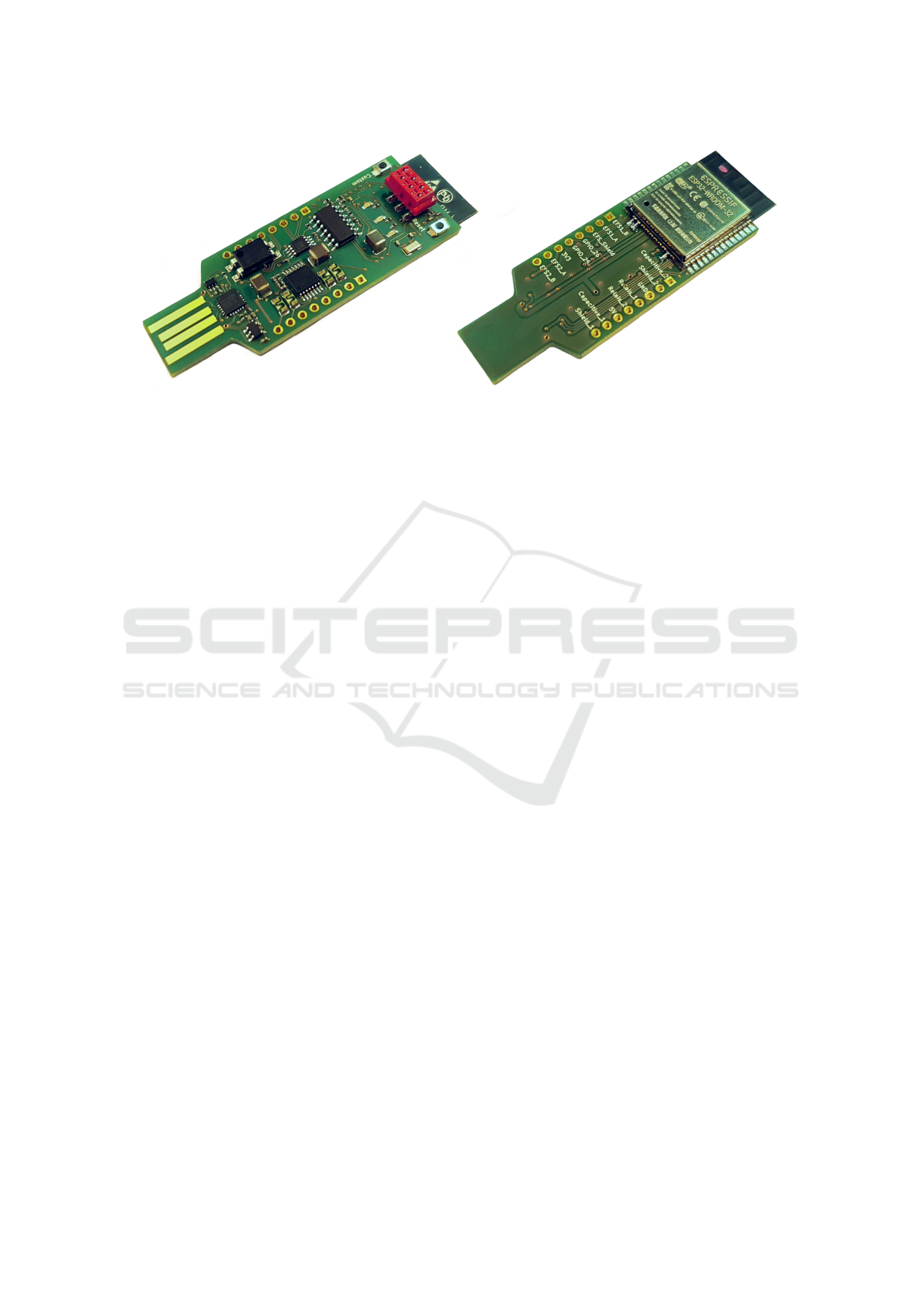
Figure 1: Front and back of the Linoc prototyping toolkit.
ing the possibility to easily customize the source code
to satisfy advanced use cases. To obtain larger sen-
sor arrays, multiple Linoc boards can be connected to
form a sensor network. One device will then take the
role of the master to aggregate sensor data of multi-
ple slaves before posting them to the server or host
computer via USB or a wireless technique. This pa-
per begins with an overview of the role of toolkits
in the modern design process, presents related work
in the field of HCI and proximity sensing alongside
the actual hardware design of the Linoc toolkit. The
Linoc hardware is detailed in section 4 followed by
the firmware design and its components, alongside
information about challenges, limitations and design
choices during the implementation process. In the fi-
nal chapter the toolkit is evaluated and an example
project is presented, demonstrating the toolkit’s fast
prototyping capabilities. This is accompanied with a
use case study to determine its usability.
2 RELATED WORK
There are a couple of toolkits in the HCI area avail-
able. In this section, we will summarize them
and compare them with the Linoc rapid prototyping
toolkit.
Hamblen et al. (Hamblen and van Bekkum, ) de-
scribe the process of building a prototyping toolkit
for future student works. They provide a cloud based
compiler to their students to eliminate setup time and
provide documentation in form of a wiki. The cloud
based compiler is an attractive way to eliminate plat-
form dependencies and can be hosted cheaply on even
weaker computing platforms like single board com-
puters.
WatchConnect (Houben and Marquardt, ) is a
toolkit to develop cross-platform applications to ex-
plore interactions between the smartwatch and a sec-
ond screen. The sensor data as well as the smart-
watch’s screen are used to extend classic input meth-
ods.
The Proximity Toolkit (Marquardt et al., ) pro-
vides an open-source hardware setup, interfaces to ac-
cess higher-level proximity representation and a tool
for visualization to use in proximity aware applica-
tions. It is designed to be hardware oblivious, so that
different sensor techniques can be used. It focuses
on the interaction with digital devices and provides
developers with information about “orientation, dis-
tance, motion, identity and location information be-
tween entities”, which are the dimensions for proxim-
ity in ubiquitous computing defined by Greenberg et
al. The authors state that their motivation is to address
the initial problem to acquire proximity sensor data
for developers. Even if sensing hardware is available,
effort is still required to translate sensor information
into proximity, as calibration and noise can have a big
impact. Their setup differs from the Linoc prototyp-
ing toolkit context as this toolkit is designed to require
no counterpart in sensors or devices to work. Further-
more Linoc aims to be unobtrusive whereas the prox-
imity toolkit focuses on intended interactions.
Midas (Savage et al., ) is a toolkit to design flexi-
ble capacitive touch sensors to apply to other objects
in order to enrich interaction possibilities. While their
focus lies on touch interactions it might be interesting
to use their toolkit for electrode design. The evalua-
tion was done in a way that the participants received a
task to complete. They received feedback that videos
can convey certain instructions better than images and
addressed this by adding animations.
The CapToolkit (Wimmer et al., ) is the second
generation of capacitive toolkits by Wimmer et
al. A stated goal is to make implicit interaction
concepts easier to develop. It supports up to eight
loading mode sensors, as shown in Figure 2 with
a sampling frequency between 25Hz and 100Hz.
SENSORNETS 2021 - 10th International Conference on Sensor Networks
50
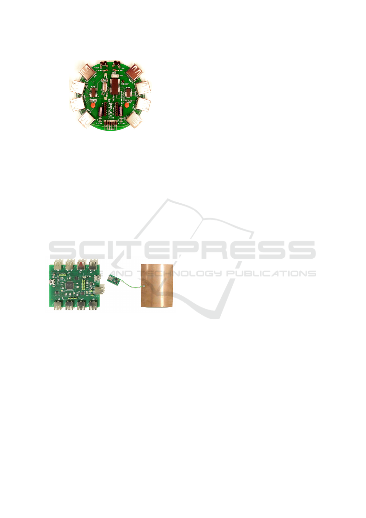
Figure 2: Captoolkit by Wimmer et al (Wimmer et al., ).
Sensor reconfiguration is possible at run-time using a
custom protocol via USB connection. User Datagram
Protocol (UDP) and Transmission Control Protocol
(TCP) interfaces can be used by the connected host
computer. The Linoc prototyping toolkit provides
this functionality directly by the sensor board, which
is made possible by recent microcontroller develop-
ment. Thus these interfaces can still be used with
battery powered sensors without physical connection
to a computer. With a 10cm x 10cm electrode the
CapToolkit is able to detect a human body at a dis-
tance up to 1m and hand movements up to 50cm. The
spatial resolution is given at 1cm at 25cm distance,
but was not reproduced in experiments by Puppedahl
et al. (Grosse-Puppendahl et al., a).
Figure 3: OpenCapSense by Puppedahl et al. (Grosse-
Puppendahl et al., b).
The OpenCapSense (shown in Figure 3) board is
inspired by the CapToolkit and addresses three short-
comings: confinement to loading mode capacitive
measurement, slow sample frequency and no options
to connect multiple sensor boards. The last aspect
is overcome by providing two Controller Area Net-
work (CAN bus) real time bus interfaces to synchro-
nize data. The board features eight Universal Serial
Bus (USB) ports for external capacitive sensors and
a framework for data exchange. It supports different
sensor types, and has been used with the three differ-
ent capacitive measuring modes, as well as EPS sen-
sors (Grosse-Puppendahl, ). It operates at frequencies
up to 250Hz with eight and up to 1kHz with one sen-
sor attached. (Grosse-Puppendahl et al., a).
The OpenCapSense board is in a way the direct
predecessor of the Linoc prototyping toolkit and has
been used in various research projects (Braun, ) in
the HCI area. It was originally designed by Tobias
Große-Puppendahl. It is thus closest related in appli-
cation purpose, albeit having a different sensor con-
cept. Linoc also focuses even more on usability than
OpenCapSense and was designed with a more modern
processor and more possibilities to connect the sensor
to a computer.
3 DESIGN GOALS
Before describing the actual hardware and software,
we will briefly discuss the design goals of the Linoc
prototyping toolkit. Linoc was built to be fitting for a
wide variety of use cases. That is why it should meet
the following requirements.
1. High connectivity
2. Easy to use
3. Support for multiple programming languages
4. Realization of advanced use cases possible
5. Chaining of multiple boards
Design goal 1 was the main reason to create Linoc.
While many available toolkits have multiple inter-
faces, most of the time additional hardware is needed
if more than a USB connection is required. This leads
to more effort required while building an actual pro-
totype both for hardware and software development.
An easy to use user experience as stated in design
goal 2 is very important if the toolkit is to be used in
an academic environment. This will enable students
and teachers alike to use Linoc seamlessly in every
kind of project. It also reduces the amount of time
that users need, both experienced and inexperienced
ones, to get their hands on the first data.
While most toolkits require a certain program-
ming language to use them, Linoc was designed so
that it can be programmed in several languages. In
times where new programming languages are created
apparently on a daily basis, it is another time consum-
ing hassle to be bound to a certain language that the
user might not prefer. With the freedom to choose the
language as stated in goal 3, the user is empowered
to use the language he is most capable of and that is
most fitting for his current project.
Having a toolkit that is easy to use should not limit
the number of use cases you can use it for. In many
cases, easy usability restricts versatility. To prevent
Linoc: A Prototyping Platform for Capacitive and Passive Electrical Field Sensing
51
Linoc from being a prototyping toolkit only for be-
ginners, we included design goal 4.
Another important aspect learned while using
other toolkits was, that no matter how many sensors
can be attached to a board, there is always a use case
where you need more. While some toolkits like Open-
CapSense have a CAN-bus interface to combine mul-
tiple boards, it is still a task that takes up several hours
to connect and reprogram them. That is why we added
design goal 5. In this way, the user is able to acquire
higher dimensional data by adding more sensors.
After explaining why we choose these design
goals, we will now focus on how we implemented
them in hardware and software.
4 HARDWARE
4.1 Microcontroller
The microcontroller used on the Linoc board has to
fulfil several requirements; The choice of the micron-
controller is a critical step because most of these re-
quirements have to be covered by the controller itself.
To be precise, the controller affects the design goals 1,
3 and 4. The ESP32 from Espressif fulfills all of these
requirements. It features Wi-Fi, Bluetooth and Eth-
ernet connectivity as high level protocols. For intra-
board communication, the user can choose between
several low level protocols such as UART, I
2
C, Inter-
IC Sound (I
2
C), CAN bus and SPI to name only the
most common ones. This makes the ESP32 a good
processor for our needs of high connectivity. The
ESP32 has enough memory to support a Real-Time
Operating System (RTOS). This allows for complex
use cases as we planed in goal 4.
Since the ESP32 is the direct successor of the
ESP8266, which was (and still is) very popular in the
maker-scene and for Internet of Things (IoT) prod-
ucts, there are a couple of toolchains for different pro-
gramming languages available.
Table 1: Programming languages and toolchains available
for the ESP32.
Toolchain Language Editor
ESP-IDF
C/C++
with FreeRTOS
Eclipse IDE
Mongoose OS C & JavaScript Browser page
MicroPython Python -
PlatformIO C/C++
Atom editor,
Eclipse IDE,
Visual Studio Code,
...
Arduino C++ Arduino IDE
Table 1 lists a selection of possible languages and
editors for the ESP32. Note that this not only is in
favor of our design goal 3, but also goal 2. This is
because the ESP32 is, amongst others, also Arduino
compatible. Arduino is a commonly used language by
beginners when it comes to embedded programming.
4.2 Capacitive Measurements
The Linoc prototyping toolkit features two capacitive
loading mode sensors. The sensors were added di-
rectly onto the board, so that in contrast to other pro-
totyping toolkits, there is no need to add more exter-
nal hardware.
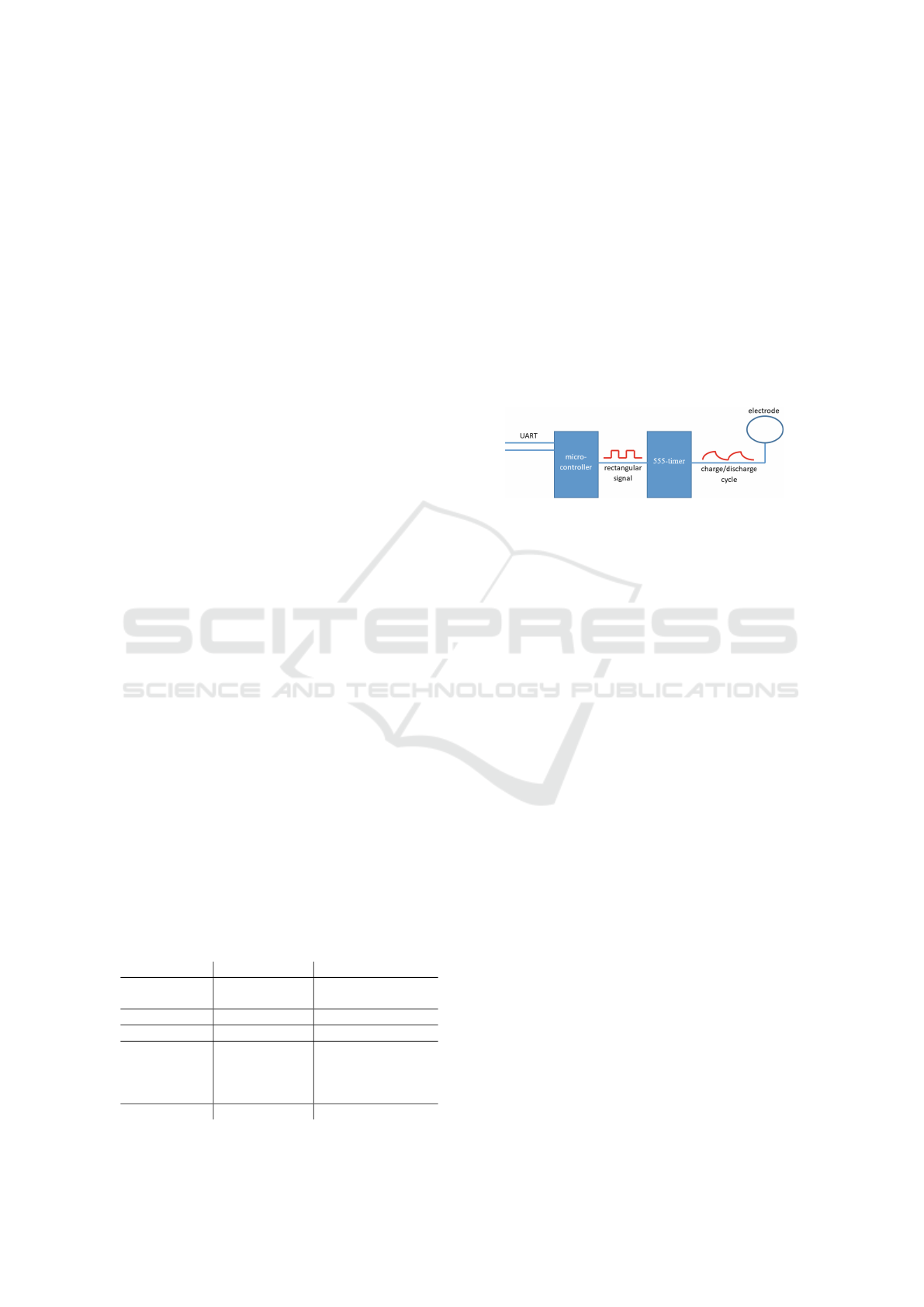
Figure 4: Model of the capacitive sensor.
The capacitive group’s main component is the 555
timer which generates the charging cycles on the elec-
trode, as shown in Figure 4, with a constant charg-
ing current. Since the current is constant, the charg-
ing process is influenced by the environment. When
a conductive objects approaches the electrode, the
resulting capacity between electrode and object in-
creases. Hence, the time needed to charge this ca-
pacitor with the same amount of current increases.
A pulse counter module in the microcontroller then
counts the number of cycles per second, which is the
final measurement parameter. The microcontroller is
also able to dis- and re-enables the 555 timers so that
it is possible to prevent cross talk when multiple sen-
sors are active at the same time.
Linoc also features a shield for both capacitive
sensors to support coaxial cable or to minimize en-
vironmental influences on selected parts of the elec-
trode. The shield is realized by a simple voltage fol-
lower, implemented with an opamp, of the capacitive
feed line.
4.3 Electric Potential Sensing
Besides the two capacitive sensors, Linoc features
two electric potential sensors. Electric potential sens-
ing is another form of capacitive sensing. The main
differences between a capacitive loading mode sen-
sor and an electric potential sensor are the detection
range, the mode of operation and the energy con-
sumption. Electric potential sensing can detect mov-
ing conductive objects in a distance of up to two me-
ters(von Wilmsdorff et al., 2018), while the range of
SENSORNETS 2021 - 10th International Conference on Sensor Networks
52
capacitive sensing is limited to about 35cm (see 6.2).
A loading mode sensor measures the capacity of a vir-
tual capacitor that is created between electrode and
user, whereas an electric potential sensor measures
the induced current that a user can transmit through
the same virtual capacitor between electrode and him-
self. This also implies that the electric potential sen-
sor of the Linoc toolkit is only able to detect move-
ments, while the loading mode sensor is capable of
sensing non-moving objects. The last difference is the
energy consumption which is lower for electric poten-
tial sensors, but since the microcontroller draws far
more power than all sensors combined and because
the Linoc toolkit is designed to be used with a USB
connection or a USB powerbank, this is not a crucial
point of the toolkit discussion.
4.4 Board Layout
Since one of the main goals in mind while designing
the Linoc prototyping toolkit is fast data acquisition,
the board features numerous connection types. The
Linoc prototyping toolkit can sent data over various
protocols, as well as raw binary data, as shown in Ta-
ble 2.
Table 2: Outputs and their correlating connectors.
Protocoll Connector
Wi-Fi (b/g/n) 2.4GHz antenna
Bluetooth 2.4GHz antenna
USB front board connector
I
2
S left and right pinouts
UART micromatch connector
Binary data over GPIO left and right pinouts
Binary data over relais left and right pinouts
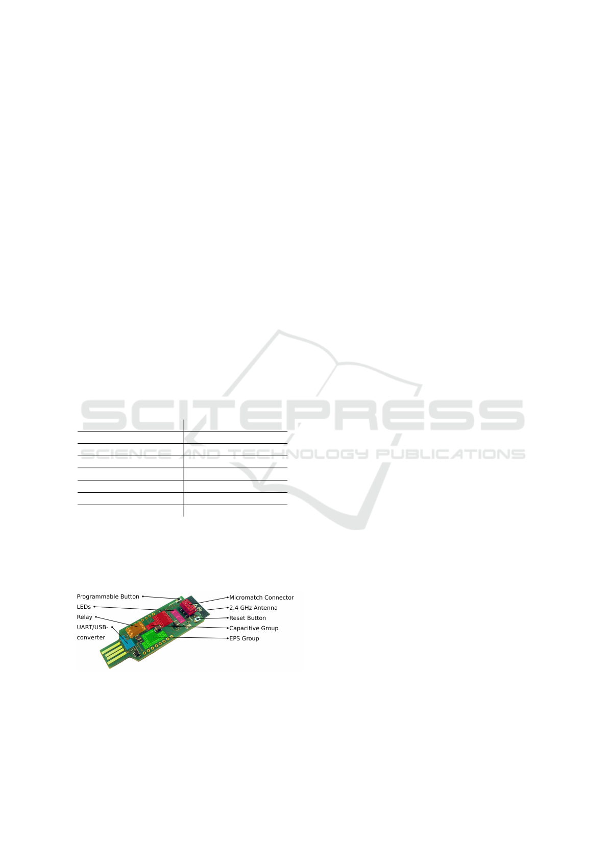
Figure 5 clarifies the location of all connec-
tors. The prototyping board also has three free pro-
grammable Light-Emitting Diodes (LEDs) as well as
a free programmable button. The second button of the
board is hard wired to reset the microcontroller.
Figure 5: Hardware layout of Linoc.
A mosfet relais was added to board (see Figure 5)
to cover more use cases (see design goal 4) without
the need of further soldering. The relais enables the
user to directly connect LEDs, piezo buzzers or other
hardware that requires more voltage and higher cur-
rents to the board (up to 30V and 1A).
The micromatch connector was added for several
reasons. Since the board should be capable of creating
sensor chains, which was discussed in goal 5, a ribbon
cable is a suitable solution. This is because, again,
no further soldering is required when crimping new
connectors to a ribbon cable. Ribbon cables can be
configured with any number of connectors which can
be spaced at any distance.
Another important feature of the toolkit is the built
in USB to UART converter. The converter is required
to flash the microcontroller. By integrating it onto
the board an external programmer, common to many
toolkits, is not required here. Note that the connection
over UART/USB does not support live debugging as
JTAG adapters do.
5 SOFTWARE
Central interface to the Linoc toolkit is a console over
the UART bus of the microprocessor, which is con-
nected to the USB interface. Without programming
or flashing, the configuration of sensor groups, sam-
pling frequency and sensor array configuration can be
changed as well as wireless connections established
and system diagnostics be printed. A help command
lists available options. This is usually sufficient to use
the toolkit in own projects and fulfills use case 2, be-
cause no further programming is required.
The software implementation is done with the
ESP-IDF and FreeRTOS in the programming lan-
guage C. This allows advanced users to access low-
level functionality of the microcontroller in order to
modify the software to their needs as aimed for in de-
sign goal 4. Multiple sensors can be connected to a
sensor array (design goal 5) and communicate via I
2
C
with each other. After initiating the setup from the
master device (the one connected to the users com-
puter), the order on the array is established by press-
ing a button on the slave devices in the respective or-
der. This allows for various physical setups.
The sensor data is transferred to the host computer
via UART, or transmitted via Wi-Fi, either by posting
to a given TCP server or by hosting a TCP server on
the toolkit to which other entities can connect to (de-
sign goal 1). This data can then be further processed
by the user with her preferred tools or programming
languages (design goal 3).
Linoc: A Prototyping Platform for Capacitive and Passive Electrical Field Sensing
53

6 EVALUATION
To generate a meaningful and comparable evaluation,
we choose to cover multiple categories identified in
the meta study by Ledo et al. (Ledo et al., ), in which
evaluation strategies and common pitfalls were iden-
tified by analyzing 68 published toolkits. Thus we
chose to evaluate in terms of usability, performance
and demonstration.
6.1 User Evaluation
To evaluate usage, a set of tasks was devised for the
participants to explore the functionality of the toolkit.
The instructions besides setup, were vaguely formu-
lated, to determine if the Linoc interfaces are designed
intuitively and the information provided through the
console sufficient. The advanced tasks were only
given as concepts to provide some freedom for the
participants to explore the toolkit. Following the set
of tasks a Likert scale questionnaire was answered by
the participants. The questionnaire is attached in Ap-
pendix 6.3. The study was carried out with eleven
participants. More information about the participants
and what operating systems they used is listed in Ta-
ble 3. Most participants needed some time to familiar-
ize with the toolkit and the way the commands work,
but became more fluent over time. The majority of
participants needed about 20 to 30 minutes to com-
plete the survey.
Table 3: Participant information.
Age 24 - 39, Average: 30
Gender Female: 4, Male: 7
Occupation School: 2, Study: 6, Work: 3
OS used Windows: 5, Mac: 2, Linux: 4
The results of the questionnaire are presented in
Table 4. The usage of the toolkit and even the com-
plex task of setting a sensor array was reported as in-
tuitive. Even participants reporting not experienced in
programming or computer systems mostly did not feel
overwhelmed by the system and a participant feeling
overwhelmed in the beginning was able to finish the
given tasks with some assistance.
Eight out of the eleven participants reported re-
ceiving assistance during the study. Nearly all partic-
ipants were able to complete all the given tasks suc-
cessfully. In most cases the assistance was limited
to occasional clarifications, only two minor technical
difficulties arose during the evaluation which resulted
in receiving more assistance than just clarifications.
As the results of the evaluation in Table 4 show,
the overall feedback is very positive. This is not only
shown by the high marks but also by the low standard
deviation, which indicates that the opinion of all par-
ticipants are nearly the same. Application ideas for
future projects as stated from the users in ”Free ques-
tions” section of the questionnaire centered around
general activity and proximity detection and integra-
tion to cloud computing.
Table 4: Results from the questionnaire, ranging from 1
(strongly agree) to 5 (strongly disagree).
Question
Mean
Median
STD
Experienced
User?
1,91 1 1,6
Similar
systems
already used?
3,09 3 1,51
Tasks
successful?
1,45 1 0,69
Feeling over-
whelmed?
4,18 5 1,25
Usage
intuitive?
1,82 1 1,25
Functionality
sufficient?
1,09 1 0,42
Sensor array
intuitive?
1,82 2 0,98
6.2 Performance
To assess the performance of the loading mode sen-
sors, the Linoc prototyping toolkit was mounted in an
automatic test stand. The test stand consists of a metal
box to shield from external influences and a conduc-
tive platform that is moved by a stepper motor. It can
be lifted up to 35cm over the sensor.
Figure 6: Data of a test run in the automated test stand in-
cluding the standard deviation.
All sensor values are recorded for several minutes,
then the platform is moved upwards 1cm. For this
test, the pulses of the 555 timer (see 4.2) were counted
for 0,5 seconds, which corresponds to a sensor sam-
SENSORNETS 2021 - 10th International Conference on Sensor Networks
54

Figure 7: Comparison of the fluid level metering in (Wimmer et al., ) (“sensor reading (units)” is plotted over “Fluid Level
[mm]”) and a reproduction using the same electrode and beer bottle on the right.
pling rate of 2 Hz. This means that over 200 samples
were collected for every position of the movable test
platform.
It is possible to distinguish between two different
distances of the test platform as long as the measured
values don’t overlap. A graphical representation with
error bars was arranged, as illustrated in Figure 6, to
visualize which distances were distinguished success-
fully and thereby concluding the maximal range of the
system. To derive if a distance is distinguishable from
the previous, following metric is used:
¯m
i
− ¯m
(i−1)
− σ
i
− σ
i−1
> 0
Meaning that if the mean value of a distance ¯m
i
minus
its standard deviation σ
i
is still bigger than the mean
value of the previous measured distance ¯m
(i−1)
, in-
cluding its standard deviation σ
i−1
, all sensor values
of these two distances can be clearly assigned.
In our tests, the maximal testable range of 35cm
of the automated test stand was detectable with the
Linoc toolkit, matching the performance of the Open-
CapSense, as shown in Figure 6. Note that this test
stand is shielded from environmental noise so that
the detectable range can be lower in noisy environ-
ments. The big standard deviation, seen at a distance
of 5mm in Figure 6, is the result of a settling time of
the sensor. This is why the first values of the load-
ing mode sensor can be observed as more noisy than
values recorded later on.
Another impact factor of the sensor range are cus-
tom firmwares. A software which generates strong
fluctuations in the energy demand of the processor
will also destabilize the sensors power supply. Very
CPU intensive tasks followed by a CPU idle time can
induce such a behaviour. To prevent this issue, Linoc
was equipped with large decoupling capacitors.
6.3 Demonstration: A Ten Minute Built
of a Fluid Level Metering
CapToolkit (Wimmer et al., ) demonstrated a fluid
level metering for a beer bottle with a 10cm x 10cm
electrode. This demonstration was repeated for com-
parison. Care was taken to buy the same beer brand
(Augustiner Lagerbier Hell). To ensure consitent re-
sults and to exclude the tester, he had to stay at a con-
stant distance and allowing the signal to tune in after
pouring out 4cl beer at a time. A calibration curve
similar to the one presented in (Wimmer et al., ) was
measured and is shown in Figure 7.
Note that the unit on the y-axis differs from the
usual unit throughout this paper. This is due to the
fact, that Wimmer et al. measure the time of the ca-
pacitive charging cycles and not the frequency. The
relationship is t = 1/ f and the absolute value deter-
mined by the sampling length.
REFERENCES
Braun, A. Application and validation of capacitive proxim-
ity sensing systems in smart environments.
Grosse-Puppendahl, T. Capacitive sensing and communica-
tion for ubiquitous interaction and environmental per-
ception.
Grosse-Puppendahl, T., Berghoefer, Y., Braun, A., Wim-
mer, R., and Kuijper, A. OpenCapSense: A rapid pro-
totyping toolkit for pervasive interaction using capac-
itive sensing. In 2013 IEEE International Conference
on Pervasive Computing and Communications (Per-
Com), pages 152–159. IEEE.
Grosse-Puppendahl, T., Braun, A., and Dellangnol, X. Pro-
totyping Capacitive Sensing Applications with Open-
CapSense. 20(2):16–21.
Hamblen, J. O. and van Bekkum, G. M. E. An Embedded
Linoc: A Prototyping Platform for Capacitive and Passive Electrical Field Sensing
55

Systems Laboratory to Support Rapid Prototyping of
Robotics and the Internet of Things. 56(1):121–128.
Houben, S. and Marquardt, N. WatchConnect: A Toolkit for
Prototyping Smartwatch-Centric Cross-Device Appli-
cations.
Ledo, D., Houben, S., Vermeulen, J., Marquardt, N.,
Oehlberg, L., and Greenberg, S. Evaluation Strate-
gies for HCI Toolkit Research. In Proceedings of the
2018 CHI Conference on Human Factors in Comput-
ing Systems - CHI ’18, pages 1–17. ACM Press.
Marquardt, N., Diaz-Marino, R., Boring, S., and Greenberg,
S. The proximity toolkit: Prototyping proxemic in-
teractions in ubiquitous computing ecologies. In Pro-
ceedings of the 24th Annual ACM Symposium on User
Interface Software and Technology - UIST ’11, page
315. ACM Press.
Savage, V., Zhang, X., and Hartmann, B. Midas: Fabri-
cating custom capacitive touch sensors to prototype
interactive objects. In Proceedings of the 25th An-
nual ACM Symposium on User Interface Software and
Technology - UIST ’12, page 579. ACM Press.
von Wilmsdorff, J., Kirchbuchner, F., Braun, A., and Kui-
jper, A. (2018). Eliminating the ground reference for
wireless electric field sensing. In Kameas, A. and
Stathis, K., editors, Ambient Intelligence, pages 90–
99, Cham. Springer International Publishing.
Wimmer, R., Kranz, M., Boring, S., and Schmidt, A. A
Capacitive Sensing Toolkit for Pervasive Activity De-
tection and Recognition. pages 171–180. IEEE.
SENSORNETS 2021 - 10th International Conference on Sensor Networks
56
Evaluation of the
Prototyping Platform
for Capacitive and
Electrical Field Sensing
1 Introduction
The Linoc toolkit is built for activity detection through electric field measurement and has two measurement techniques:
capacitive and passive electric field sensing.
Its benefits are easy reconfiguration of sensor groups and connectivity without knowledge of embedded systems.
2 Setup
The Linoc sensor is connected to the computer via USB. The electrodes are connected to the pin-outs at the side of the
board. Labels are on the bottom side of the chip.
2.1 Connection Setup
To communicate with the sensor a couple of steps are necessary.
Windows:
In the device-manager it can be checked if the Linoc is detected correctly. If this is not the case, the right device driver
has to be installed from www.ftdichip.com. The connection is then made with the program Putty (putty.org).
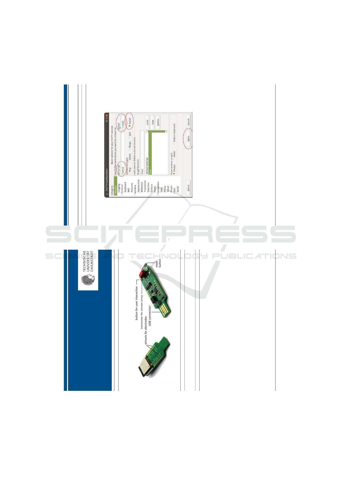
After the installation, start Putty with the option serial, the com-port from the device-manager, a baud rate 115200 and
without hard- and software control flows. Messages should now appear in the terminal.
Linux:
Start a terminal (Ctrl+Alt+t). The current user has to belong to the group dialout
This can be checked with following command:
groups | grep ’dialout’
If the output is empty the user has to be added to the group using following command:
sudo usermod -aG dialout $USER
A reboot is necessary to apply the changes.
Linux & MacOS Communication happens easiest via Putty.
(if Putty is not available it can be installed with ‘sudo apt install putty’. Alternatives are screen, minicom, or other pro-
grams supporting serial connection). Putty is started with the option serial, the port (like /dev/ttyUSB0) and a baudrate
of 115200
Messages should now appear in the terminal.
� setup was completed successfully � setup was not necessary
� messages from sensor are displayed � setup was not possible
1
Evaluation of the Prototyping Platform for Capacitive and Passive Electrical Field Sensing
2.2 Visualization (optional)
A graphical visualization helps understanding sensor values. A multitude of programs can be used for this. As example
the Arduino IDE is mentioned here (https://www.arduino.cc/en/Main/Software). The respective port has to be selected
in the menu ‘Tools’. Afterwards the‘Serial Plotter’ can be started from the same menu.
The ‘Serial Monitor’ can be used to change the configuration.
Abbildung 1: Putty window. relevant settings marked with circles
2
APPENDIX
Questionaire
Linoc: A Prototyping Platform for Capacitive and Passive Electrical Field Sensing
57
Evaluation of the Prototyping Platform for Capacitive and Passive Electrical Field Sensing
3 Configuration
3.1 Console
The configuration of the Linoc toolkit happens over a console. The console can be reached through pressing the button
on the board, on the side with the connectors notch.
Typing help displays an overview of available commands.
� Console is displayed � Commands are executed
3.2 Changing the Sensor Configuration
With the commands capacitive_switch, eps_switch and frequency_set, the sensor configuration can be changed. With exit
the sensor returns to displaying values. sensor_info displays the current setup.
Please configure the sensor to the configurations described in the sections below and check if the values change if you
move your hand towards the measuring electrode. For the configuration it might be necessary to change the placement
of the electrodes on the chip.
3.2.1 Task 1: Configuration #1
Active sensors: Capacitive 1 & 2
Sampling frequency: 2 Hz
� Two value pairs are printed per second
3.2.2 Task 2: Configuration #2
Active sensors: EPS 1
Sampling frequency: 50 Hz
� Values appear noticeably faster
3.3 Task 3: Connect to Wi-Fi
Connect to the provided Wi-Fi hotspot and start a TCP server on the sensor.
Stop the connection again afterwards.
� connection established successfully. � values can be queried from another device
4 Sensor Array
Multiple Linoc sensors can be connected to a sensor array (Daisy Chain).
The command to initiate is ‘daisy_chain init’.
Follow the instructions provided in the console from now on.
The connected devices takes the role of the master and queries sensor values of the other sensors.
4.1 Task 4: Sensor Array Setup
Connect 3 sensors with the provided cable to a sensor array
4.2 Task 5: Configuration
Follow the instructions in the console to setup all sensors.
� Number of sensors detected correctly � Sensor values of all sensors are printed correctly
4.3 Break up the Sensor Array
Stop the sensor array. This is done with the command ‘daisy_chain break’.
Check if the sensor can be used as before.
� Sensor array stopped � Sensor can be used as before
3
Evaluation of the Prototyping Platform for Capacitive and Passive Electrical Field Sensing
5 Evaluation
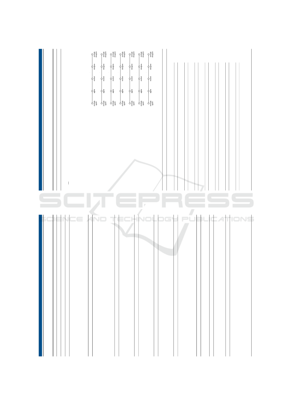
Please answer following questions briefly:
Age:
Years
Gender: � F � M � n.b. � n.A.
What is your current occupation: � school � study � apprenticeship � work � something else
Which operating system are you using? � Windows � Mac � Linux � n.A.
Did you receive help with the tasks?: � Yes � No
Are you experienced in programming and/or computer systems?
Have you worked with similar toolkits?
Did you manage to fulfill the tasks with the information provided?
Did you at any time had the feeling to be overburdened?
Was the handling of the Linoc toolkit intuitive?
Do you think the functionality is sufficient?
Was the setup of the sensor array intuitive?
5.1 Free questions
What did you like about the system?
What did you dislike?
Could you imagine using the toolkit in a project?
Which applications can you imagine?
Which aspects should be improved?
What would facilitate the handling?
Further comments:
4
SENSORNETS 2021 - 10th International Conference on Sensor Networks
58
