Procam Calibration from a Single Pose of a Planar Target
Ghani O. Lawal and Michael Greenspan
Dept. Electrical and Computer Engineering, Ingenuity Labs, Queen’s University, Kingston, Ontario, Canada
Keywords:
Procam, Calibration, Optimization, Stereovision, Homography.
Abstract:
A novel user friendly method is proposed for calibrating a procam system from a single pose of a planar
chessboard target. The user simply needs to orient the chessboard in a single appropriate pose. A sequence
of Gray Code patterns are projected onto the chessboard, which allows correspondences between the camera,
projector and chessboard to be automatically extracted. These correspondences are fed as input to a nonlinear
optimization method that models the projection of the principle points onto the chessboard, and accurately
calculates the intrinsic and extrinsic parameters of both the camera and the project, as well as the camera’s
distortion coefficients. The method is experimentally validated on a real procam system, which is shown to be
comparable in accuracy with existing multi-pose approaches. The impact of the orientation of the chessboard
with respect to the procam imaging places is also explored through extensive simulations.
1 INTRODUCTION
Projector camera (procam) systems are an effective
approach for implementing range sensing and inter-
acting with a 3D environment. For static scenes, the
procam system can be used as an inexpensive 3D
scanner (Moreno and Taubin, 2012). They can also
be used in dynamic settings where the camera cap-
tures information about the environment in real time
and the projector displays any visual content that the
user provides. This allows the system to implement
Spatial Augmented Reality (SAR) (Audet and Oku-
tomi, 2009). This type of projection-based augmented
reality (AR) enables the user to interact with the en-
vironment naturally without the requirement to have
devices attached to their bodies as in head mounted
or handheld AR (Yang et al., 2016). Shader lamps,
smart projectors and augmented paintings on non-
planar surfaces are a few of the specific applications
of SAR achieved through procam systems (Bimber
and Raskar, 2005).
Prior to use, the intrinsic and extrinsic parame-
ters of the procam system must be acquired, which
is a process referred to as calibration. Projectors are
similar to cameras with respect to their system geom-
etry, except that they emit light rather than absorb-
ing it, which allows many techniques developed for
camera calibration to be adapted for calibrating a pro-
jector, provided that methods such as structured light
are able to obtain camera-projector pixel correspon-
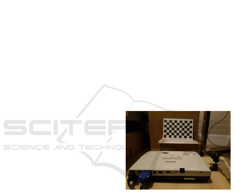
Figure 1: Procam system setup. The projector (white) and
the camera (black) are placed in front of the chessboard tar-
get.
dences. This work makes use of Gray code patterns to
accomplish this task (Salvi et al., 2004). Through the
use of structured light, the difficulty in establishing
camera-projector pixel correspondences is largely al-
leviated and becomes computationally trivial, unlike
passive camera-camera stereovision systems. How-
ever the issue remains that to calibrate a procam sys-
tem, 3D correspondences need to be established either
by moving a planar target to multiple poses, or by
making use of a 3D calibration target that possesses
specific shape and detail requirements.
This work proposes a user friendly method for
calibrating a procam system from a single pose of
Lawal, G. and Greenspan, M.
Procam Calibration from a Single Pose of a Planar Target.
DOI: 10.5220/0010327708170827
In Proceedings of the 16th International Joint Conference on Computer Vision, Imaging and Computer Graphics Theory and Applications (VISIGRAPP 2021) - Volume 5: VISAPP, pages
817-827
ISBN: 978-989-758-488-6
Copyright
c
2021 by SCITEPRESS – Science and Technology Publications, Lda. All rights reserved
817

a planar chessboard pattern of known dimensions as
shown in Figure 1. Camera-chessboard and projector-
chessboard homographies are established with cam-
era and chessboard after the camera and projector
correspondences have been identified. Using their
respective homographic relationship with the chess-
board both the camera and projector project their prin-
cipal points onto it thereby establishing a definition
for their respective principal axis. Once their princi-
pal axis are defined their respective projection param-
eters are optimized using the Levenberg-Marquardt
algorithm. Once the projection relationship the chess-
board has with the camera and projector is calculated
it is trivial to compute the extrinsic parameters that re-
late the camera location to the projector location. The
user does not need to move any object or require any
special purpose or expensive equipment.
The accuracy of the recovered parameters from
this method are comparable to those derived from
mainstream techniques, all of which require multi-
ple repositioning of a calibration target. To our best
knowledge, this is the first example of procam cali-
bration from a single pose of a planar target, which is
the main contribution of this paper.
A second contribution is the implementation of a
PnP-based technique for determining the precision of
a group of calibration parameters. This was included
to enhance the reprojection error metric, which may
not necessarily indicate how stable the final parame-
ters are when used to determine arbitrary 3D points in
space. The benefit of this technique is revealed from
the experimental results, which characterize the accu-
racy of the method and demonstrates that it compares
favorably with other more standard approaches.
2 BACKGROUND
There are many types of procam calibration methods,
all of which require one or more of the following;
• Images of a 2D target in several poses;
• A pre-calibrated camera;
• A precise electro-mechanical actuator, or;
• A 3D object that satisfies specific shape and detail
constraints.
Each of these requirements increases complexity and
therefore decreases accessibility for the user, espe-
cially outside of a lab environment, as well as increas-
ing potential sources of error.
Methods based on Zhang’s flexible calibration ap-
proach (Zhang, 2000) are the most common, due to
its effectiveness and popularity for camera calibra-
tion. The main difference between such methods are
the structured light technique used to acquire pro-
jector correspondences, and the patterns used on the
2D planar target, which tend to be chessboard cor-
ners (Zhang and S. Huang, 2006)(Huang et al., 2018),
circles (Zhongwei Li, 2008)(Huang et al., 2015) or
sometimes QR codes (Audet and Okutomi, 2009) and
random dot patterns (Yang et al., 2016). Whichever
structured light technique or 2D planar target pattern
is used, this type of calibration requires at least three
poses of the 2D target plane to be imaged by the
procam system (Zhang, 2000). It is an exacting and
time consuming task to orient a planar target in mul-
tiple unique positions, while ensuring that it remains
prominently in the fields of view of both the camera
and the projector.
A method called visual servoing can be used to
calibrate a projector given a pre-calibrated camera.
The projector is to project a chessboard onto a physi-
cal one such that the corners of the physical and pro-
jected chessboard align (Berry et al., 2013). This is
done my modelling the projector as a virtual camera
whose pose can be altered and is viewing the chess-
board though the actual projector remains in the same
position throughout the calibration process. Using
control theory the virtual camera is moved so that it
is in the same pose as the projector that it is mod-
elling, once the virtual camera and projector occupy
the same position the projected chessboard will align
with the physical one (Chaumette and Hutchinson,
2006) (Mosnier et al., 2009). Despite the camera
(which is effectively half of the procam system) be-
ing precalibrated, at least 10 distinct poses of a chess-
board are needed to calibrate the projector intrinsic
and the extrinsic parameters. This therefore has the
same drawbacks as Zhang’s method applied to pro-
cam calibration.
It is possible to calibrate a procam system if the
position of a planar target can be precisely controlled.
This allows Tsai’s camera calibration method (Tsai,
1987) to be repurposed for procam calibration. In
Tai’s method, calibration can be achieved with only
two poses of a planar target, under the condition that
these poses are related by a pure translation, and that
the accurate translation value is known (Chen et al.,
2009) (Zhang, 2000). This can only be done if one has
access to a programmable actuator, which severely
limits the accessibility of this method.
Through the decomposition of a radial fundamen-
tal matrix and utilizing Bougnoux’s equations, it is
possible to simultaneously calibrate the projector and
camera (Li et al., 2017). Methods based on the afore-
mentioned matrix and equations only require a 3D
(i.e. non-planar) object imaged in a single pose to
complete the calibration process (Yamazaki et al.,
VISAPP 2021 - 16th International Conference on Computer Vision Theory and Applications
818

2011). However, for the values to be known to a
global scale, the dimensions of the object must be
known, and because it is based on a fundamental ma-
trix, the object has shape and detail requirements that
must be met for the results to be stable, including that
it should not be rotational or translation invariant and
provide enough geometric variation to facilitate suc-
cessful optimization (Resch et al., 2015).
3 METHOD
The proposed method makes use of an error metric
based upon mapping a set of known 2D coordinates
on a planar chessboard pattern onto each of the cam-
era and projector planes. This linear mapping com-
prises the respective homographies between the two
pairs of planes (i.e. chessboard to camera, and chess-
board to projector) as well as the projection matrices
formed by the camera and projector intrinsic and ex-
trinsic parameters. In the case of the camera, a non-
linear transformation of the image is also applied, to
correct for radial distortions.
The error metric is used to drive a non-linear opti-
mization process over a set of parameters that model
the projections. The optimization is done separately
for each of the camera and the projector, and its suc-
cessful convergence is reasonably robust to the selec-
tion of initial values. Upon convergence, the resulting
optimized parameters convert directly to establish the
intrinsic and extrinsic parameters of the camera and
projector, the accuracy of which is then independently
evaluated with a separate test.
3.1 Model and Notation
The pinhole model is used to describe the camera and
projector (Hartley and Zisserman, 2003) as shown in
Figure 2 , with respective intrinsic matrices K
c
and K
p
defined as:
K
c
=
f
c
0 u
o
c
0 α
c
f
c
v
o
c
0 0 1
, K
p
=
f
p
0 u
o
p
0 α
p
f
p
v
o
p
0 0 1
(1)
Here, f
c
and f
p
represent the camera and projector fo-
cal lengths , and [u
o
c
v
o
c
]
T
and [u
o
p
v
o
p
]
T
are their
respective principal points. The aspect ratio between
the camera’s u- and v-axes is denoted α
c
. The pro-
jector’s aspect ratio is assumed to be unity, due to
the high uniformity of commercial projectors, and so
α
p
= 1 and this term is excluded from further consid-
eration. Camera lenses can exhibit significant radial
distortion (Hartley and Kang, 2007), which can be es-
timated and corrected using the two parameter divi-
sion model (Huang et al., 2020) that was introduced
by Fitzgibbon (Fitzgibbon, 2001). Alternately, pro-
jector lenses tend to be high quality and considered to
possess relatively negligible amounts of radial distor-
tion (Drar
´
eni et al., 2011), and so we do not include
projector radial distortion in our calibration model.
Let m
c
= [u
c
v
c
]
T
and ˆm
c
= [ ˆu
c
ˆv
c
]
T
represent cor-
responding undistorted and distorted 2D points in the
camera image plane. The division model transforms
ˆm
c
to m
c
through the following:
u
c
= u
o
c
+
ˆu
c
− u
o
c
1 + k
1
r
2
+ k
2
r
4
v
c
= v
o
c
+
ˆv
c
− v
o
c
1 + k
1
r
2
+ k
2
r
4
(2)
where k
1
and k
2
are the free parameters that need to
be estimated, and r is the Euclidean distance between
the principal point and the distorted point.
The intrinsic matrices of the camera and projector
allow 3D points defined in their respective coordinate
systems to be transformed to their respective image
planes as follows:
sm
c
= K
c
M
c
sm
p
= K
p
M
p
(3)
where m
j
= [u
j
v
j
]
T
are 2D points on the camera ( j =
c) or projector ( j = p) plane, and M
j
= [x
j
y
j
z
j
]
T
are 3D points defined in their corresponding coordi-
nate reference systems as shown in Figure 2. Points
on the planar chessboard calibration target are defined
in the chessboard coordinate frame, but are not a pri-
ori defined in either the camera or projector coordi-
nate frames. To map these points from the chessboard
frame to the camera or projector frames, the rotation
and translation values between the chessboard and
pinhole devices need to be determined. Let [R
c
|T
c
]
and [R
p
|T
p
] represent the rotation and translation of
the chessboard in the camera and projector frames re-
spectively, with the rotation matrices parameterized
by the XYZ-Euler angles (ψ
c
,ν
c
,φ
c
) and (ψ
p
,ν
p
,φ
p
).
Multiplying the rotation and translation matrices by
the corresponding intrinsic matrix allows for points
defined in the chessboard coordinate system to be pro-
jected onto the camera and projector image planes:
sm
c
= K
c
[R
c
|T
c
]M
b
sm
p
= K
p
[R
p
|T
p
]M
b
(4)
where M
b
= [x
b
y
b
z
b
]
T
is a 3D point on the chess-
board plane described in the chessboard frame as
shown in Figure 2.
The chessboard by construction lies on the x
b
-y
b
plane, and so M
b
= [x
b
y
b
0]
T
. Let m
b
= [x
b
y
b
]
T
rep-
resent a 2D coordinate on the chessboard plane such
that M
b
= [m
b
T
0]
T
. The metric dimension of the
Procam Calibration from a Single Pose of a Planar Target
819
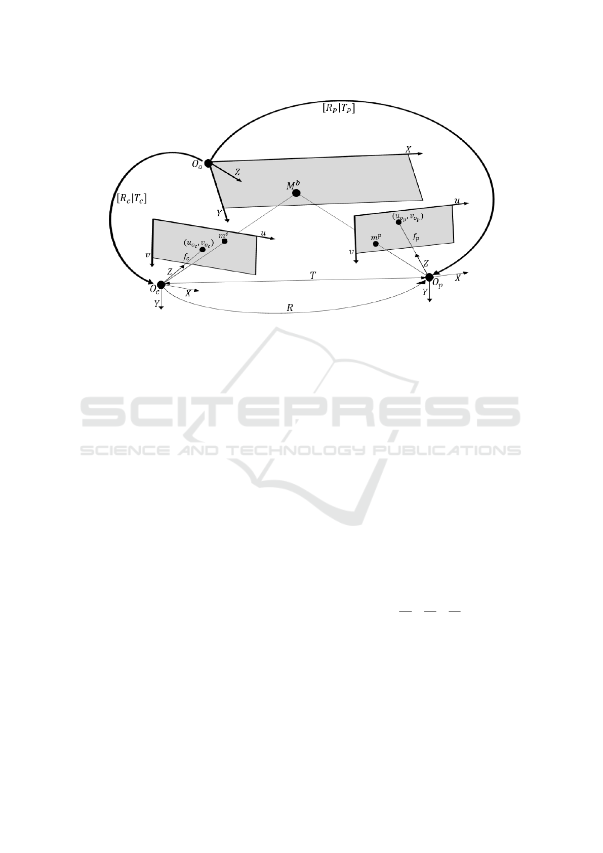
Figure 2: Procam System Model.
chessboard is known, and its N corner coordinate val-
ues are stored as {m
b
i
}
N
i=1
. The value of any m
b
i
is
then related to the corresponding 2D m
c
i
and m
p
i
points
through a pair of 2D homographies:
m
b
i
= H
B
C
m
c
i
= H
B
P
m
p
i
(5)
Two sets of six parameters, denoted by θ
c
for the
camera and θ
p
for the projector, need to be deter-
mined to fully calibrate the procam system:
θ
c
= { f
c
,α
c
,φ
c
,x
c
o
,y
c
o
,z
c
o
}
θ
p
= { f
p
,v
o
p
,φ
p
,x
p
o
,y
p
o
,z
p
o
}
(6)
Here, O
c
= [x
c
o
y
c
o
z
c
o
]
T
, φ
c
, and O
p
= [x
p
o
y
p
o
z
p
o
]
T
,
φ
p
, denote the center of projection and the rotation
about the principal axis of the camera and projector
respectively.
3.2 Camera Calibration
The radial distortion present in the camera lens must
first be calculated before θ
c
can be optimized. This
is accomplished by first extracting the epipole from
the fundamental matrix between ˆm
c
i
and m
b
i
, which is
known as the fundamental matrix of radial distortion
for which the epipole is equivalent to the center of
distortion (Hartley and Kang, 2007). The center of
distortion extracted from this technique is used as the
principal point for the camera. Next, the distortion
coefficients k
1
and k
2
are computed using the one-shot
method of (Huang et al., 2020), which is based on the
assumption that the homography between the b
i
and
m
c
i
is proportional to the mapping between ˆm
c
i
and m
c
i
.
Once k
1
and k
2
are calculated the undistorted camera
image points m
c
i
can be recovered using Eq. 2.
Having calculated and corrected the camera radial
distortion, the first step in optimizing θ
c
is to define
the principal axis of the camera. First the homogra-
phy H
B
C
between the camera and chessboard is calcu-
lated from Eq. 5 using the known m
b
i
and the extracted
and undistorted m
c
i
. Homography H
B
C
is then used to
project the camera frame principal point [u
o
c
v
o
c
]
T
onto the chessboard plane. Let C
B
o
be the 3D loca-
tion of [u
o
c
v
o
c
]
T
projected onto the chessboard, ex-
pressed in the chessboard coordinate frame. By def-
inition the principal axis is the z-axis
~
Z, which origi-
nates at the origin of the camera reference frame, and
intersects with the image plane at point [u
o
c
v
o
c
]
T
and
at the chessboard at point C
B
o
as shown in Figure 3. A
rotation matrix A is formed by the following:
~
Z = C
B
o
− O
c
~
Y =
~
Z × [1 0 0]
T
~
X =
~
Y ×
~
Z
(7)
A =
~
X
|
~
X|
~
Y
|
~
Y |
~
Z
|
~
Z|
(8)
The directions of the x- and y-axes are controlled by
φ
c
, which rotates them about the z-axis, creating a new
rotation matrix A
c
= AR
Z
(φ
c
). Next, A
c
and O
c
are
then used to calculate the extrinsic values between the
chessboard and the camera:
R
c
= A
T
c
, T
c
= −A
T
× O
c
(9)
The location of C
B
o
is constant throughout the en-
tire optimization process, therefore the camera is al-
VISAPP 2021 - 16th International Conference on Computer Vision Theory and Applications
820
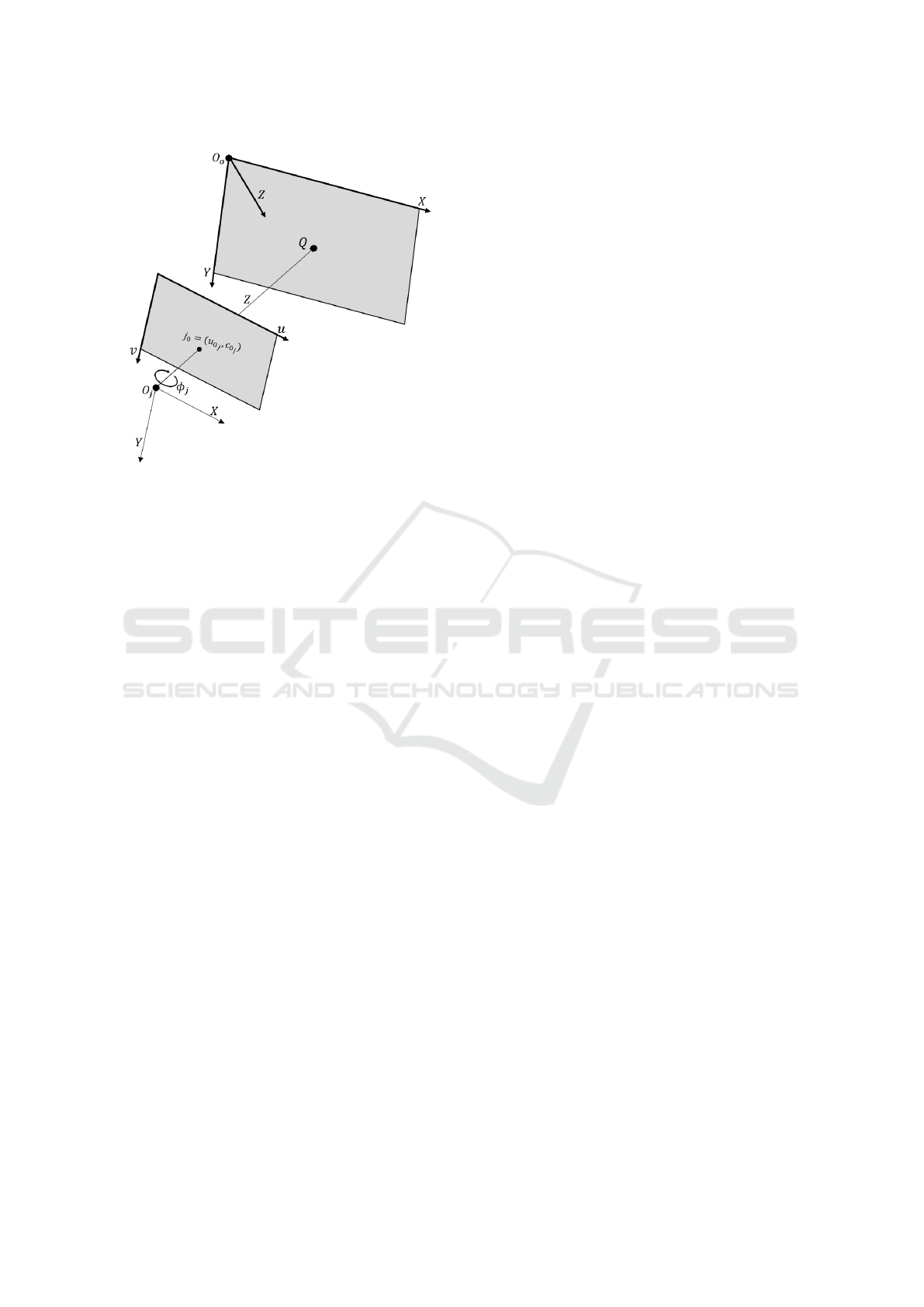
Figure 3: Formation of Principal Axis. For the camera, j =
c and Q = C
B
o
. For the projector, j = p and Q = P
B
o
.
ways pointed towards the same location on the chess-
board plane. Thus, as the value of x
c
o
changes the the
camera is rotated about its y axis and as the value of y
c
o
changes the camera is rotated about its x axis. There
is no need to include ψ
c
and ν
c
, the rotations about
the camera’s x and y axis respectively, in θ
c
.
The corners of the chessboard are then projected
onto the camera image plane using Eq. 3 with each
m
c
i
replaced by m
i
(θ
c
). The absolute difference be-
tween the undistorted camera image points m
c
i
and
the transformed image points m
i
(θ
c
) is the error met-
ric used to optimize θ
c
, by applying the Levenberg-
Marquardt algorithm to minimize the following cost
function with respect to θ
c
:
θ
∗
c
= argmin
θ
c
N
∑
i=1
||m
c
i
− m
i
(θ
c
)||
2
(10)
3.3 Projector Calibration
As with the camera, the principal axis of the projector
must be defined to optimize θ
p
. Homography H
B
C
is
then used to project [u
o
p
v
o
p
]
T
onto the chessboard
plane, so that P
B
o
is the 3D point of intersection of the
projector optical axis and the chessboard plane, ex-
pressed in the chessboard coordinate system as shown
in Figure 3. u
o
p
will always be equal to half the width
of the projector image plane. As before with the cam-
era, and analogous to Eq. 9, a rotation matrix A matrix
is formed using Eq. 11, albeit with φ
c
replaced by φ
p
.
Here, the directions of the x- and y-axes are con-
trolled by φ
p
, which rotates them about the z-axis, cre-
ating a new rotation matrix A
p
= AR
Z
(ψ). The A
p
and
O
p
values are then used to calculate the extrinsic pa-
rameters between the chessboard and camera:
R
p
= A
T
p
, T
p
= −A
T
× O
p
(11)
The location of P
B
o
is confined to a line segment on
the chessboard plane throughout the entire optimiza-
tion process. Thus, as the value of x
p
o
changes the the
projector is rotated about its y axis and as the values
of v
op
and y
p
o
change the projector is rotated about its
x axis. There is no need to include ψ
p
and ν
p
, the ro-
tations about the projector’s x and y axis respectively,
in θ
p
.
The corners of the chessboard are then projected
onto the projector image plane using Eq. 3, with m
p
i
replaced by m
i
(θ
p
). The absolute difference between
the projector image points m
p
i
and transformed image
points m
i
(θ
p
) is the error metric used to optimize θ
p
.
Analogous to the application of Eq. 10 for the cam-
era parameters, the Leveberg-Marquardt algorithm is
then applied to minimize the following cost function
with respect to the projector parameter set θ
p
:
θ
∗
p
= argmin
θ
p
N
∑
i=1
||m
p
i
− m
i
(θ
p
)||
2
(12)
3.4 Projector Camera Calibration
Lastly the procam extrinsic parameters are recovered
from [R
c
|T
c
] and [R
p
|T
p
]:
R = R
p
R
T
c
T = T
p
− R T
c
(13)
3.5 Initial Values
Initial estimates of the values of the two calibration
parameter sets are required to commence the opti-
mization process, with the values used listed in Ta-
ble 1. The initial values of the focal lengths are
the diagonal pixel length of their respective image
planes (Yamazaki et al., 2011) where r
c
, r
p
, c
c
, c
p
are the number of rows and columns in the projector
and camera image planes. The value of α
c
is initial-
ized to 1 as experimentally the aspect ratio is typi-
cally close to unity for pinhole devices (Moreno and
Taubin, 2012). The vertical coordinate of the projec-
tor principal point, v
o
p
, is usually near the top or bot-
tom of the image plane, and so it was initialized to half
the height of the projector image plane. The values of
O
c
= O
p
= [0 0 2w
b
]
T
and φ
c
= φ
p
= 0
◦
were ini-
tialized based on the reasonable assumption that the
chessboard is facing both the camera and the projec-
tor, and that their x- and y-axes are similarly oriented.
The width of the chessboard is represented by w
b
.
Procam Calibration from a Single Pose of a Planar Target
821
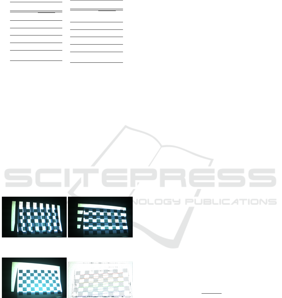
Table 1: Calibration Parameter Set Initial Values.
Camera
θ
c
Initial Value
f
c
p
r
2
c
+ c
2
c
α
c
1
ψ
c
0
x
c
o
0
y
c
o
0
z
c
o
2w
b
Projector
θ
p
Initial Value
f
p
q
r
2
p
+ c
2
p
v
p
r
p
/2
ψ
p
0
x
p
o
0
y
p
o
0
z
p
o
2w
b
3.6 Correspondence Acquisition
The N chessboard corner coordinates are extracted
to subpixel accuracy from the camera image and are
stored in the array { ˆm
c
i
}
N
i=1
, with the ˆ symbol indicat-
ing that these coordinates exhibit the radial distortion,
i.e. they have not yet been undistorted by applying
Eq. 2. The projector frame coordinates correspond-
ing to each of these camera frame coordinates are ac-
quired by decoding a sequence of 46 projected Gray
Code patterns, two of which are shown in Figure 4
and utilizing local homographies in the same manner
as (Moreno and Taubin, 2012). The projector corre-
spondences are then stored in the array {m
p
i
}
N
i=1
, or-
dered such that each ˆm
c
i
, m
p
i
and m
b
i
correspond. Fig-
ure 5 shows the raw camera image and the computed
projector ‘image’.
Figure 4: Horizontal and vertical Gray Codes projected onto
chessboard.
Figure 5: Camera Image (left) and projector image (right).
4 EXPERIMENTS
Two sets of experiments were performed to test the
accuracy of the proposed procam calibration method.
One utilized a real procam system programmed with
OpenCV in C++, and the other was a simulation pro-
grammed in MATLAB. The real experiments show
that different poses affect the accuracy of the calibra-
tion, and the simulated experiments allow us to isolate
and identify what elements of the chessboard pose are
the most influential factors that impact accuracy.
4.1 ProCam Setup
The proposed calibration method was applied to a
physical procam system. The camera used for this
experiment was a BlackFly Point Grey color cam-
era with a resolution of 1280×800 and the projec-
tor was the Epson PowerLite 1771W with a resolu-
tion of 1920×1080 as shown in Figure 1. A chess-
board of dimensions 21×26.5 cm with 10×6 = 60
corners was used as the calibration plane. The chess-
board was moved to seven distinct poses where the
Gray Code sequence was projected, to establish sets
of correspondences between the camera and projector
points (described in Sec. 3.6).
4.2 Accuracy Metrics and Reference
Values
To assess the accuracy and validity of the calibration
parameters, the calibration method of (Moreno and
Taubin, 2012) was used to establish reference values
to compare against. They effectively used Zhang’s
method (Zhang, 2000) to calibrate both the camera
and the projector. Zhang’s method requires minimally
three distinct poses of a planar surface to calibrate a
pinhole device, with 46 Gray Code images acquired
for each chessboard pose to automatically establish
correspondences between projector and camera coor-
dinates.
As seven distinct poses of the chessboard were
acquired, there are multiple groups of calibration pa-
rameters that can arise, each resulting from a unique
combination of the seven distinct chessboard poses.
Each such combination is referred to here as a pose
set. Each pose set contains between three and seven
chessboard poses, and so the number of pose sets is:
7
∑
i=3
7!
i!(7 − i)
= 99 (14)
The reprojection error was used to determine the
validity and of the calculated calibration parameters,
as well as the two quantities σ
|T |
and σ
T
, where σ
T
is
the standard deviation of the projector location with
respect to the camera, and σ
|T |
is the standard devi-
ation of the projector’s distance |T | from the camera
(known as the stereovision baseline). Assume the first
group of calibration parameters were obtained using
a combination of poses one, two and three. The in-
trinsic parameters from that pose set are used with
VISAPP 2021 - 16th International Conference on Computer Vision Theory and Applications
822

Table 2: Daniel and Gabriel Reprojection Errors.
Reprojection Error
Stat Cam Pro Stereo
Set A 0.251 0.775 0.577
Set B 0.256 0.815 0.604
Mean 0.274 0.855 0.637
Std Dev 0.047 0.308 0.216
Table 3: Standard Deviation of Baseline.
Translation Vector
Stat σ
X
σ
Y
σ
Z
σ
T
σ
|T |
Set A 4.49 1.70 1.76 5.11 2.97
Set B 0.79 0.90 0.53 1.31 0.70
Mean 6.06 2.91 2.46 7.27 3.86
Std Dev 5.53 3.11 2.07 6.55 4.20
the point correspondences extracted from the Gray
Code images to calculate the (X,Y,Z,|T |) values be-
tween the camera and projector, resulting in seven
(X,Y,Z,|T |) values, i.e. one for each pose, including
the three poses (one, two and three) used to calculate
the parameters. The σ
T
value is equal to the square
root of the sum of the variances of the (X ,Y, Z) co-
ordinates, and σ
|T |
is equal to the standard deviation
of the |T | values. Methods that solve the PnP prob-
lem can be used to extract the pose of pinhole device
with respect to an object defined from a known set of
planar or non-planar points if the intrinsic parameters
are known (Lepetit et al., 2009) (Lu, 2018). Therefore
OpenCV’s solvePnP function is used in conjunction
with Eq. 13 to calculate σ
|T |
and σ
T
.
These standard deviation metrics are included in
the analyses because reprojection error may not ac-
curately predict the correctness of a possible 3D re-
construction. No matter how the chessboard is moved
and oriented in 3D space one should be able to calcu-
late the same values for the procam extrinsic param-
eters using a PnP method because the pose between
the camera and projector is rigid and thus constant in
a procam system. Thus when a PnP method is applied
with the procam intrinsic parameters to calculate the
extrinsics, T and |T | should remain constant, although
a small amount of variation is expected due to noise.
Therefore the σ
|T |
and σ
T
measures the precision of
the calibration.
The reprojection errors, σ
|T |
and σ
T
were calcu-
lated for all 99 pose sets. Pose set 99 was calibrated
using all seven poses, and pose set 4 was calibrated
using only poses four, five and six. For convenience,
these are referred to as Set A and Set B, respectively.
Set A produced the lowest reprojection error for the
camera, projector and procam system, while the pa-
Table 4: Daniel and Gabriel Calibration Results.
Parameter Reference Values Mean Std Dev
f
c
1535.7 1541.8 57.4
α
c
f
c
1537.9 1542.3 54.7
u
0
c
666.4 666.4 10.1
v
0
c
518.3 518.3 21.6
f
p
2506.4 2428.2 179.4
α
p
f
p
2507.2 2430.7 157.7
u
0
p
1007.9 996.1 20.4
v
0
p
1046.0 1074.7 50.1
ψ 0.87 1.82 1.42
ν 14.44 14.91 0.71
φ -0.25 -0.12 0.34
X -170.05 -174.12 6.57
Y -41.25 -38.37 6.49
Z -65.35 -77.90 36.32
Table 5: Camera Intrinsic Parameters.
Set f
c
α
c
f
c
u
0
c
v
0
c
1 1492.91 1497.45 653.77 542.00
2 1400.22 1402.12 624.69 549.09
3 1907.85 1911.66 646.03 543.90
4 1585.58 1589.60 676.94 517.70
5 1484.22 1492.50 677.57 516.98
6 1493.04 1494.36 621.42 526.89
7 2139.43 2142.98 611.36 560.52
rameters of Set B resulted in the lowest values for σ
|T |
and σ
T
as shown in Tables 2 and 3. The parameters of
Set B are used as the reference values because transla-
tion standard deviation values are less than half of Set
A’s, and their resultant reprojection errors are within
no more than 5% of Set A’s. This indicates that the pa-
rameters resulting from Set B will be able to extract
depth to a higher degree of accuracy than Set A for
arbitrary objects because while Set A is marginally
more accurate than Set B, Set A is significantly less
precise than Set B.
4.3 Real Data Results
Each of the seven chessboard poses produced a dif-
ferent final group of procam calibration parameters
when the proposed method was used. The values of
the parameters is largely dependent on the orientation
between the pinhole devices and the chessboard. Ta-
ble 5 and 6 show the calculated intrinsic parameters of
the camera and projector respectively for each pose.
The camera reprojection error is largely dependent
on the sum of the absolute values of ψ
c
and ν
c
. This
pattern is clearly displayed in Table 7 which also lists
|∆ f
c
|, the absolute difference between the reference
values and calculated focal length of the camera for
Procam Calibration from a Single Pose of a Planar Target
823

Table 6: Projector Intrinsic Parameters.
Set f
p
f
p
u
0
p
v
0
p
1 2812.21 2812.21 960.00 908.01
2 3364.91 3364.91 960.00 820.48
3 2537.86 2537.86 960.00 1065.43
4 2586.15 2586.15 960.00 1042.14
5 2357.50 2357.50 960.00 1039.86
6 1893.04 1893.04 960.00 1159.24
7 2554.36 2554.36 960.00 1077.02
Table 7: Camera Calibration Accuracy Metrics.
Set ψ
c
ν
c
|ψ
c
| + |ν
c
| |∆ f
c
| Error
1 -19.11 -8.32 27.43 42.78 0.30
2 -12.25 -9.42 21.68 135.47 0.42
3 -4.47 4.92 9.40 372.16 1.2
4 -9.62 1.74 11.36 49.88 0.44
5 -5.69 -29.44 35.12 51.47 0.39
6 -14.18 -15.64 29.82 42.65 0.31
7 -4.13 5.01 9.14 603.73 1.62
each set. Set one, five and six possess |ψ
c
| + |ν
c
| val-
ues over 25 degrees and their average reprojection er-
ror across the seven images is less then 0.4. Sets 3
and 7 both have |ψ
c
| + |ν
c
| less than 10 degrees av-
erage reprojection error is greater than 1. Set two
and set four both were both calibrated with |ψ
c
|+ |ν
c
|
values that are greater than 10 degrees but less then
25 degrees, and their average reprojection errors are
0.42 and 0.44 respectively. Generally the higher the
|ψ
c
|+|ν
c
| value, the lower the reprojection errors that
the intrinsic matrix will provide. Also, the sets that
provide three of the lowest reprojection error, set one,
four and six produce |∆ f
c
| values that are less than the
standard deviation value of f
c
in Table 4.
The projector reprojection error is also dependent
of the chessboard rotation about its x- and y-axis, but
in a different manner than the camera. Sets three, four,
five and seven possess |ν
p
| that are all greater than 13
degrees, and each of their mean reprojection errors
are less than 1.5. Sets one, two and six all posses |ν
p
|
values less than 10 degrees and consequently their re-
projection errors are all greater than 1.5 as displayed
in Table 8. Therefore generally the greater the |ν
p
|
value, the lower the associated reprojection errors that
the intrinsic matrix will provide. |∆ f
p
|, the absolute
difference between the reference focal length and cal-
culated focal length is also displayed in Table 8, the
sets that provide the lowest four reprojection errors
(i.e. sets three, four, five and seven), produce |∆ f
p
|
values that are less than the standard deviation of f
p
in Table 4.
The accuracy of the extrinsic parameters which
are displayed in Table 9 are dependent on the accu-
Table 8: Projector Calibration Accuracy Metrics.
Set ψ
p
ν
p
|∆ f
p
| Error
1 -22.03 7.05 305.02 1.57
2 -16.39 5.10 857.72 2.81
3 1.69 14.46 30.66 0.96
4 -8.23 17.92 78.95 0.96
5 -6.44 -13.63 149.70 1.25
6 -9.15 -1.82 614.15 2.27
7 -2.16 17.81 47.17 1.01
Table 9: ProCam Euler Angles and Translation Vector.
Euler Angles Translation Vector
Set ψ ν φ X Y Z
1 -2.77 15.41 -1.06 -170.20 -39.13 8.66
2 -5.13 14.22 -1.76 -163.19 -39.14 124.57
3 -1.69 14.46 -0.53 -201.81 -23.20 -186.90
4 1.24 16.19 -0.63 -178.27 -36.52 -62.35
5 1.66 15.74 -0.25 -164.90 -34.38 -73.10
6 3.63 14.23 0.86 -170.68 -35.38 -155.81
7 1.53 12.85 0.19 -211.10 -20.29 -255.61
racy of the intrinsic parameters. Intrinsic parameters
dictate the location of the image plane relative to the
center of distortion, and where the ray connecting a
3D point and the center of projection intercept the as-
sociated image plane. For example, the Z value of
set two and set seven diverge the most from the ref-
erence value, with values 189.92 and 190.26 mm re-
spectively. The projector focal length produced from
set two deviates from the reference value the most
compared to the six other projector focal lengths.
Likewise for the camera focal length produced by set
seven. Sets four and five produce two of the top four
calibration parameters for the camera and the projec-
tor, and as a result have the most accurate Z value.
The results of the σ
|T |
, σ
T
and the stereo reprojec-
tion error are highly correlated. Generally, the closer
the calibration parameters (both intrinsic and extrin-
sic) are to the reference value, the smaller the errors
and translation standard deviations are, as shown in
Table 10. Set one and three have the same stereo re-
projection, but their σ
T
value differs by about 2 mm
and their σ
|T |
value differ by about 7 mm. This sug-
gests that despite possessing the same correspondence
error, the calibration parameters of set three would
provide a better surface reconstruction than set one.
4.4 Simulation Results
From the results of the real procam system experi-
ments, it is shown that that the pose of the chessboard
relative to the camera and projector directly affect the
VISAPP 2021 - 16th International Conference on Computer Vision Theory and Applications
824
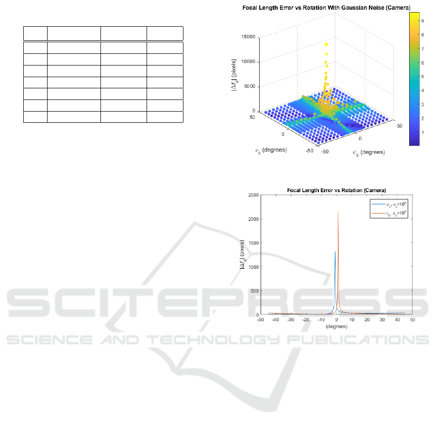
Table 10: PNP Translation Vector and Stereo Reprojection
Error Results.
Set Magnitude Location Stereo
1 10.45 11.40 1.13
2 17.94 21.40 2.02
3 3.68 9.64 1.13
4 1.49 2.34 0.75
5 1.48 2.99 0.93
6 11.69 20.72 1.62
7 6.74 18.62 1.40
calibration accuracy. This simulated experiment iso-
lates and examines this phenomenon more precisely,
by rotating the projector and camera individually with
respect to the chessboard to identify how the varying
degrees of rotation affect calibration accuracy. The
value of |∆ f
c
| and |∆ f
p
| are highly correlated with
their respective reprojection errors as shown in Ta-
ble 7 and 8 and are therefore used as the accuracy
metrics for this experiment. The simulated K
c
values
are; f
c
= 1539, α
c
= 1.004, u
0
c
= 674, and v
0
c
= 512.
The simulated K
p
values are; f
p
= 2421, α
p
= 1.002,
u
0
p
= 1013, and u
0
p
= 1065. The resolution of the
simulated camera and projector are 1280×800 and
1900×1080 pixels respectively. The simulated chess-
board was 21. × 26.5 cm with 10 × 6 = 60 corners.
Let (ψ
c
,ν
c
) and (ψ
p
,ν
p
) be the rotations about x-
and y-axes for the camera and projector respectively.
The principal point to calibrate the camera was shifted
5 pixels to the right and downwards from its true value
to account for the real world issue that the calculated
center of distortion is not located in the exact same
place as the ground truth principal point of the cam-
era. The assumptions about the projector intrinsic ma-
trix in this section are consistent with the assumptions
made in the previous section. Throughout all rota-
tions, the translation vector for both devices were kept
constant, along with the rotations about the z-axis (i.e.
φ) as well as their respective intrinsic matrices.
4.4.1 Camera
The value of |∆ f
c
| generally decreases as |ψ
c
| + |ν
c
|
increases, as shown in Figure 6 where yellow points
signify high error and dark blue points signify low er-
ror. Figure 7 shows a plot of |∆ f
c
| vs. ψ
c
, where
ν
c
= 10
◦
∀ (ψ
c
,|∆ f
c
|), and |∆ f
c
| vs ν
c
where ψ
c
=
10
◦
∀ (ν
c
,|∆ f
c
|). Despite the fact that for each of the
aforementioned graphs one of the angles is fixed, they
represent the overall relationship between the focal
length error and (ν
c
,ψ
c
), which is that |∆ f
c
| expo-
nentially decays as |ψ
c
| and |ν
c
| increase.
Figure 6: Camera Focal Length Error vs ψ
c
,ν
c
.
Figure 7: Rotate ψ
c
, ν
c
= 10
◦
and ν
c
, ψ
c
= 10
◦
.
4.4.2 Projector
The overall relationship between |∆ f
p
| and (ψ
p
,ν
p
)
is not the same as the camera’s due to the differ-
ent set of assumptions regarding the intrinsic param-
eters. The |∆ f
p
| value still exponentially decays as
|ν
p
| increases for all ψ
c
= θ, as shown in Figures 8
and 9. However, the relationship between |∆ f
p
| and
ν
p
changes depending on the corresponding ψ
p
, as
shown in Figures 9. As ν
p
is kept constant from -45
to 45 degrees, the relationship between |∆ f
p
| and ψ
p
transitions from generally increasing with ψ
p
, expo-
nentially decaying with |ψ
p
| and generally decreasing
with ψ
p
.54tr
4.5 Discussion
The best intrinsic calibration results from the pro-
posed method are comparable to the results of Daniel
and Gabriel’s technique. The reprojection error of the
camera using intrinsic values from set one and set six
are within one standard deviation of the mean repro-
jection error from (Moreno and Taubin, 2012). All
Procam Calibration from a Single Pose of a Planar Target
825
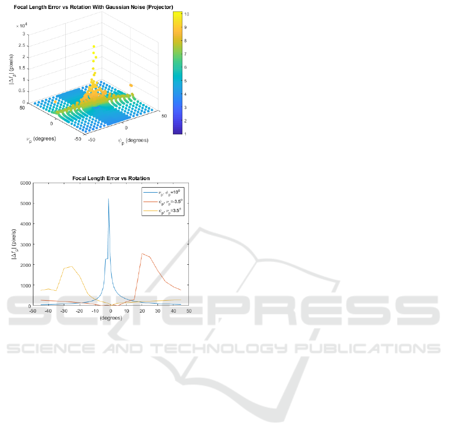
Figure 8: Projector Focal length Error vs ψ
p
,ν
p
.
Figure 9: Rotate ν
p
,ψ
p
= 10
◦
; ψ
p
,ν
p
= −3.5
◦
; and
ψ
p
,ν
p
= 3.5
◦
.
sets where |ψ
c
| + |ν
c
| > 10
◦
resulted in reprojection
errors below 0.45 for the camera. The reprojection
error of the projector using intrinsic values from set
three, four and seven are within one standard devia-
tion of the mean reprojection error from (Moreno and
Taubin, 2012) and all sets where |ν
p
| > 13
◦
resulted
in reprojection errors below 1.3 despite not account-
ing for distortion.
The best procam calibration results from the pro-
posed method are also comparable to the results of
Daniel and Gabriel’s technique. All sets used to cal-
ibrate the system with the proposed technique except
set two resulted in σ
T
values within a standard devi-
ation of the mean value in Table 10. Set three, four,
five and six, where at least either |ψ
c
| + |ν
c
| > 10
◦
or |ν
p
| > 13
◦
achieved σ
T
values less than then the
mean of the Zhang-style calibration method. Sets
four and five are the only ones that resulted in σ
|T |
values that are within one standard deviation of the
value returned by Set B and are also less than the
mean value. They are also the only two sets where
|ψ
c
| + |ν
c
| > 10
◦
and |ν
p
| > 13
◦
and are therefore
able to achieve a stereo reprojection error of less than
1. The stereo reprojection error from set four is also
within one standard deviation of the reprojection error
derived from the ground truth method in Table 2.
5 CONCLUSIONS
This work has proposed a simple and accurate method
of calibrating a procam system. It is very user
friendly, requiring only a single pose of the planar
chessboard target, without any requirement to reposi-
tion the target to multiple poses. It therefore contains
none of the practical drawbacks and inconveniences
of mainstream techniques, while maintaining compa-
rable reprojection errors and stability of the estimated
parameters. The conditions that provide the best re-
sults are easy to follow and are reproducible; orient
the chessboard with respect to the camera and projec-
tor so that |ψ
c
| + |ν
c
| > 10
◦
degrees and |ν
p
| > 13
◦
degrees, respectively. Generally the calibration accu-
racy improves as both quantities increase.
ACKNOWLEDGEMENTS
The authors would like to acknowledge and thank Ep-
son Canada, the Natural Sciences and Engineering
Research Council of Canada, and the Ontario Centres
of Excellence, for their support of this work.
REFERENCES
Audet, S. and Okutomi, M. (2009). A user-friendly
method to geometrically calibrate projector-camera
systems. In 2009 IEEE Computer Society Conference
on Computer Vision and Pattern Recognition Work-
shops, pages 47–54.
Berry, F., Aider, O. A., and Mosnier, J. (2013). A visual
servoing-based method for procam systems calibra-
tion. Sensors, 13(10):13318–13333.
Bimber, O. and Raskar, R. (2005). Spatial Augmented Re-
ality: Merging Real and Virtual Worlds. A K Peters.
Chaumette, F. and Hutchinson, S. (2006). Visual servo con-
trol, Part I: Basic approaches. IEEE Robotics and Au-
tomation Magazine, 13(4):82–90.
Chen, X., Xi, J., Jin, Y., and Sun, J. (2009). Accurate
calibration for a camera–projector measurement sys-
tem based on structured light projection. Optics and
Lasers in Engineering, 47(3):310 – 319. Optical Mea-
surements.
Drar
´
eni, J., Roy, S., and Sturm, P. F. (2011). Methods for
geometrical video projector calibration. Machine Vi-
sion and Applications, 23:79–89.
VISAPP 2021 - 16th International Conference on Computer Vision Theory and Applications
826

Fitzgibbon, A. W. (2001). Simultaneous linear estimation
of multiple view geometry and lens distortion. In Pro-
ceedings of the 2001 IEEE Computer Society Con-
ference on Computer Vision and Pattern Recognition.
CVPR 2001, volume 1, pages I–I.
Hartley, R. and Kang, S. B. (2007). Parameter-free radial
distortion correction with center of distortion estima-
tion. IEEE Transactions on Pattern Analysis and Ma-
chine Intelligence, 29(8):1309–1321.
Hartley, R. and Zisserman, A. (2003). Multiple view geom-
etry in computer vision. Cambridge university press.
Huang, B., Ozdemir, S., Tang, Y., Liao, C., and Ling, H.
(2018). A single-shot-per-pose camera-projector cali-
bration system for imperfect planar targets. pages 15–
20.
Huang, K., Ziauddin, S., Zand, M., and Greenspan, M.
(2020). One shot radial distortion correction by di-
rect linear transformation. In 2020 IEEE International
Conference on Image Processing (ICIP), pages 473–
477.
Huang, Z., Xi, J., Yu, Y., and Guo, Q. (2015). Accurate pro-
jector calibration based on a new point-to-point map-
ping relationship between the camera and projector
images. Applied Optics, 54.
Lepetit, V., Moreno-Noguer, F., and Fua, P. (2009). Epnp:
An accurate o(n) solution to the pnp problem. Inter-
national Journal of Computer Vision, 81.
Li, F., Sekkati, H., Deglint, J., Scharfenberger, C., Lamm,
M., Clausi, D., Zelek, J., and Wong, A. (2017).
Simultaneous projector-camera self-calibration for
three-dimensional reconstruction and projection map-
ping. IEEE Transactions on Computational Imaging,
3(1):74–83.
Lu, X. (2018). A review of solutions for perspective-n-
point problem in camera pose estimation. Journal of
Physics: Conference Series, 1087:052009.
Moreno, D. and Taubin, G. (2012). Simple, accurate, and
robust projector-camera calibration. In 2012 Second
International Conference on 3D Imaging, Modeling,
Processing, Visualization Transmission, pages 464–
471.
Mosnier, J., Berry, F., and Ait-Aider, O. (2009). A new
method for projector calibration based on visual ser-
voing.
Resch, C., Naik, H., Keitler, P., Benkhardt, S., and Klinker,
G. (2015). On-site semi-automatic calibration and
registration of a projector-camera system using ar-
bitrary objects with known geometry. IEEE Trans-
actions on Visualization and Computer Graphics,
21(11):1211–1220.
Salvi, J., Pag
`
es, J., and Batlle, J. (2004). Pattern codifi-
cation strategies in structured light systems. Pattern
Recognition, 37(4):827–849.
Tsai, R. (1987). A versatile camera calibration technique
for high-accuracy 3d machine vision metrology using
off-the-shelf tv cameras and lenses. IEEE Journal on
Robotics and Automation, 3(4):323–344.
Yamazaki, S., Mochimaru, M., and Kanade, T. (2011). Si-
multaneous self-calibration of a projector and a cam-
era using structured light. pages 60–67.
Yang, L., Normand, J., and Moreau, G. (2016). Practi-
cal and precise projector-camera calibration. In 2016
IEEE International Symposium on Mixed and Aug-
mented Reality (ISMAR), pages 63–70.
Zhang, S. and S. Huang, P. (2006). Novel method for struc-
tured light system calibration. Optical Engineering -
OPT ENG, 45.
Zhang, Z. (2000). A flexible new technique for camera cal-
ibration. IEEE Transactions on Pattern Analysis and
Machine Intelligence, 22(11):1330–1334.
Zhongwei Li, Yusheng Shi, C. W. Y. W. (2008). Accurate
calibration method for a structured light system. Op-
tical Engineering, 47(5):1 – 9 – 9.
Procam Calibration from a Single Pose of a Planar Target
827
