
A Study on the Influence of Omnidirectional Distortion on CNN-based
Stereo Vision
Julian Bruno Seuffert
a
, Ana Cecilia Perez Grassi
b
, Tobias Scheck
c
and Gangolf Hirtz
d
Faculty of Electrical Engineering and Information Technology,
Chemnitz University of Technology, Reichenhainer Str. 70, Chemnitz, Germany
Keywords:
Omnidirectional, Fish Eye, Indoor, 3D, CNN, Stereo Vision.
Abstract:
Stereo vision is one of the most prominent strategies to reconstruct a 3D scene with computer vision tech-
niques. With the advent of Convolutional Neural Networks (CNN), stereo vision has undergone a break-
through. Always more works attend to recover the depth information from stereo images by using CNNs.
However, most of the existing approaches are developed for images captured with perspective cameras. Per-
spective cameras have a very limited field of view of around 60
◦
and only a small portion of a scene can be
reconstructed with a standard binocular stereo system. In the last decades, much effort has been conducted in
the research field of omnidirectional stereo vision, which allows an almost complete scene reconstruction if
the cameras are mounted at the ceiling. However, as omnidirectional images show strong distortion artifacts,
most of the approaches perform an image warping to reduce the reconstruction complexity. In this work, we
examine the impact of the omnidirectional image distortion on the learning process of a CNN. We compare
the results of a network training with perspective and omnidirectional stereo images. For this work, we use
AnyNet and a novel dataset of synthetic omnidirectional and perspective stereo images.
1 INTRODUCTION
Convolutional Neural Networks (CNN) have gained
an undisputed protagonist in different fields of com-
puter vision such as detection and classification of ob-
jects and semantic segmentation. In recent years, their
use has also reached stereo vision.
A typical stereo vision algorithm can be described
through four steps: matching cost computation, cost
aggregation, optimization and disparity refinement
(Scharstein et al., 2001). A disparity map gives the
difference between the position of matching pixels on
the left and right images of a stereo pair. This values
reveal information about the depth of the scene, i.e.,
the distance of the scene’s objects to the camera.
Multiple works have advocated to perform these
steps, or a subset of them, using CNNs. Some ar-
chitectures focus on predicting the matching cost and
leave the other steps for a post-processing (
ˇ
Zbontar
and LeCun, 2016) and some CNNs include all stereo
steps (Mayer et al., 2016).
a
https://orcid.org/0000-0002-0636-3385
b
https://orcid.org/0000-0003-1171-903X
c
https://orcid.org/0000-0002-1829-0996
d
https://orcid.org/0000-0002-4393-5354
One of the most important assumption in the exist-
ing works is that the matching cost computation is
performed on rectified images. The matching cost
gives the degree of correspondence between inten-
sity values in the right and left images of the stereo
pair. In the case of rectified images, this correspon-
dence occurs only along horizontal epipolar lines (See
Sec. 3.1). This latter means that the search for match-
ing pixels is restricted to a single dimension, which
significantly simplifies the algorithm. For perspec-
tive images, the rectification process is straightfor-
ward and it only implies a correction of the images
regarding the cameras’ arrangement. However, this
latter is no longer the case if we consider a different
camera model such as the omnidirectional one.
Omnidirectional cameras are gaining attention in
computer vision because of their wide field of view
(FOV). However, this advantage is accompanied by
a high radial distortion of the image. In the case of
stereo images, this distortion also affects the epipo-
lar lines, which take the form of curves. As a conse-
quence, now the search for the matching cost must be
carried out in two dimensions. To overcome this prob-
lem, omnidirectional stereo vision approaches, both
standard and CNN-based, pre-process the images by
Seuffert, J., Grassi, A., Scheck, T. and Hirtz, G.
A Study on the Influence of Omnidirectional Distortion on CNN-based Stereo Vision.
DOI: 10.5220/0010324808090816
In Proceedings of the 16th International Joint Conference on Computer Vision, Imaging and Computer Graphics Theory and Applications (VISIGRAPP 2021) - Volume 5: VISAPP, pages
809-816
ISBN: 978-989-758-488-6
Copyright
c
2021 by SCITEPRESS – Science and Technology Publications, Lda. All rights reserved
809

unwrapping them according to a given model, in or-
der to obtain parallel epipolar lines. This latter allows
using the same approaches as for perspective images.
However, the unwrapping process introduces errors
and loss of information.
In this work, we study how the difference between
epipolar lines and curves influences the learning pro-
cess of a CNN trained to predict the disparity map.
Although the first CNN architectures especially de-
veloped for omnidirectional stereo images have been
recently introduced, they still include image transfor-
mation to obtain horizontal epipolar lines (Won et al.,
2019b).
A direct comparison of how the geometry of om-
nidirectional images affects the prediction results is
still missing in the literature. This paper investigates
how well a CNN architecture, which can successfully
learn the disparity maps from perspective images, can
also learn the disparity maps from omnidirectional
ones. For this purpose, we select the network AnyNet
(Wang et al., 2019), which has achieved state-of-the-
art results on perspective images.
As there is a lack of omnidirectional stereo
datasets for aligned cameras with ground truth
depth maps, we present a novel synthetic
stereo dataset called THEOStereo (available on
https://www.tu-chemnitz.de/etit/dst/forschung/
comp vision/theostereo). We train AnyNet with both
omnidirectional and perspective images from THEO-
Stereo and analyze the accuracy of the predicted
disparity maps. Moreover, we study the importance
of considering global information on omnidirectional
stereo images in contrast with perspective ones.
2 RELATED WORK
With the advent of CNNs, the generation of disparity
maps in stereo vision has undergone a breakthrough.
Different network architectures have been developed
to predict the disparity maps from image pairs. MC-
CNN (Matching Cost by using CNN) is an architec-
ture based on siamese networks to predict the match-
ing cost on small image patches (
ˇ
Zbontar and Le-
Cun, 2016). The resulting matching cost is then im-
proved by a series of post-processing steps as cross-
based cost aggregation, semiglobal matching (SGM)
(Hirschm
¨
uller, 2008), a left-right consistency check,
subpixel enhancement, a median and a bilateral filter.
In (Luo et al., 2016) a faster siamese matching
network is presented. Luo et al. treat the problem as
a multi-class classification, where the classes are all
possible disparities and compute the inner product
between the two representations of the given
siamese architecture by using a product layer. Disp-
Net (Mayer et al., 2016) is an end-to-end network
that directly predicts disparities for an image pair
without post-processing.
GC-Net (Geometry and Context Network) is a
deep learning architecture for regressing disparity
(Kendall et al., 2017). By using a soft-argmin layer,
GC-Net learns disparity as a regression problem,
rather than classification, improving the performance
and enabling sub-pixel accuracy.
PSMNet (Pyramid Stereo Matching Network)
incorporates global context information in stereo
matching though a pyramid network (Chang and
Chen, 2018).
AnyNet (Wang et al., 2019) predicts a fast initial
disparity map and then progressively improves it by
predicting residual maps. In this way, the disparity
estimation is carried out in stages, being able to ex-
tract a prediction from each one at any time. With this
architecture, AnyNet can trade off computation effort
and accuracy at inference time. We describe AnyNet
in Sec. 3.3.
All previously mentioned works assume a recti-
fied perspective image pair as input. Recently the
first architectures for omnidirectional stereo images
have been introduced. Won et al. present a series
of works for omnidirectional depth estimation from a
wide-baseline multi-view (four cameras) omnidirec-
tional stereo setup (Won et al., 2019a; Won et al.,
2019b; Won et al., 2020).
Their first work presents SweepNet (Won et al.,
2019b), a CNN that computes the matching costs of
grayscale equirectangular image pairs warped from
the omnidirectional images. The resulting cost vol-
ume is then refined by applying SGM and the final
depth map is estimated. However, SweepNet has
problems to manage occlusions, which are typical for
the proposed wide-baseline omnidirectional setup. To
overcome this problem, Won et al. propose Omni-
MVS (Won et al., 2019a), an end-to-end deep neural
network consisting of three blocks: Feature extractor,
spherical sweeping and cost volume computation. In
(Won et al., 2020), they extend OmniMVS to consider
an entropy boundary loss for learning better regula-
rization in the cost computation block.
All these three works include the warp of the in-
put omnidirectional images (SweepNet) or of their
feature maps (OmniMVS) onto concentric global
spheres. In our work, we are interested in studying
how well a CNN that successfully predicts disparity
from perspective stereo images, like AnyNet, is also
capable to generate disparity maps from omnidirec-
tional stereo images. This involves learning a diffe-
VISAPP 2021 - 16th International Conference on Computer Vision Theory and Applications
810
rent geometry, which requires global information as
shown in Sec. 5.
There are different datasets of stereo images. Two
of the most used perspective stereo image datasets are
Scene Flow (Mayer et al., 2016) and KITTI (Geiger
et al., 2012; Menze and Geiger, 2015).
Won et al. present synthetic omnidirectional
datasets for indoor and outdoor scenes (Won et al.,
2019b; Won et al., 2019a; Won et al., 2020). How-
ever, all these datasets are exclusively designed, and
therefore limited, for their proposed setup of four
cameras with wide-baseline and non-aligned viewing
directions.
In our work, we introduce a datatset similar to
THEODORE (Scheck et al., 2020), called THEO-
Stereo. This comprises synthetic omnidirectional
stereo images of indoor scenes and their depth maps
as ground truth.
3 STEREO VISION
Stereo vision is beside structure from motion, struc-
tured light, time of flight and other techniques a com-
mon approach to reconstruct scenes in 3D (Giancola
et al., 2018). Stereo vision works in a similar manner
to the spatial scene perception of humans by retriev-
ing depth information from at least two cameras anal-
ogous to two eyes. Those two cameras are located
at position C
C
C
0
and C
C
C
1
in a camera coordinate system
(CCS) with the origin at C
C
C
0
. In this section, we briefly
introduce the concepts of perspective and omnidirec-
tional stereo vision. A more complete and detailed
explanation of these concepts can be found in (Hart-
ley and Zisserman, 2004) and (Kannala and Brandt,
2006).
3.1 Stereo Vision with Perspective
Cameras
For performance reasons, perspective cameras are
commonly arranged in a so-called canonical camera
setup, where image planes are coplanar and their x-
axes are collinear. A canonical setup following the
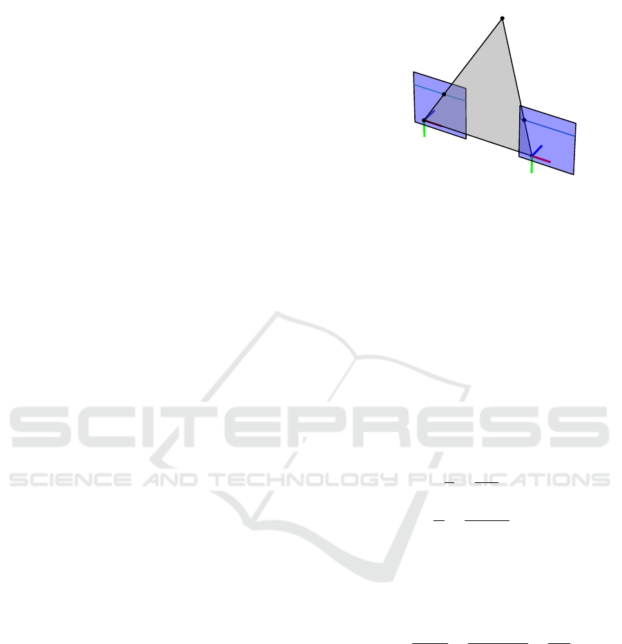
perspective camera model is shown in Fig. 1. We de-
fine the camera on the left, i.e., at position C
C
C
0
, as the
reference camera.
A point in the CCS is denoted as P
P
P =
[x
cam
, y
cam
, z
cam
]
T
. For a perspective camera model,
the projection of P
P
P on the first camera’s image plane
is given by the point P
P
P
0
persp
= [x
0
img
, y
0
img
]
T
. This im-
age point is defined in an image coordinate system
with origin on the image’s upper left corner. In or-
der to retrieve the location of the point P
P
P, the point
P
P
P
˜
P
P
P
0
persp
˜
P
P
P
1
persp
C
C
C
0
C
C
C
1
l
l
l
0
l
l
l
1
Figure 1: Canonical binocular stereo vision setup following
the perspective camera model. The point P
P
P is projected onto
the image planes at position P
P
P
0
persp
and P
P
P
1
persp
. Both points
have the same y-coordinate as the epipolar lines l
l
l
0
and l
l
l
1
are collinear and parallel to the x-axes of the images.
P
P
P
1
persp
= [x
1
img
, y
1
img
]
T
on the right image, which cor-
responds to P
P
P
0
persp
on the left image, must be found.
This is done by applying a stereo matching tech-
nique that searches for P
P
P
1
persp
along the corresponding
epipolar line l
l
l
1
.
We define the x-distance between each image
point P
P
P
0
perps
and P
P
P
1
perps
and their corresponding optical
axes as x
l
= x
0
img
−c
x
and x
r
= x
1
img
−c
x
, respectively,
where c
x
is the x-coordinate of the image center (See
Fig. 2). Applying similar triangles, following rela-
tions can be obtained:
x
l
f
=
x
cam
z
cam
, (1)
x
r
f
=
x
cam
− b
z
cam
, (2)
where f stands for the focal length of the cameras
and b for the baseline (distance between cameras). By
subtracting Eq. 2 from Eq. 1, the relationship between
the depth z
cam
and the disparity d = x
0
img
−x
1
img
can be
retrieved as follows:
z
cam
=
f · b
x
l
− x
r
=
f · b
x
0
img
− x
1
img
=
f · b
d
. (3)
The arrangement of disparity and depth values on
two-dimensional maps with respect to the image of
the reference camera (at C
C
C
0
) are called disparity map
and depth map, respectively.
3.2 Stereo Vision with Omnidirectional
Cameras
The main advantage of using omnidirectional cameras
in stereo vision is their large FOV, which allows, e.g.,
to capture a whole indoor scene when the cameras are
A Study on the Influence of Omnidirectional Distortion on CNN-based Stereo Vision
811
C
C
C
0
C
C
C
1
x
l
x
r
P
P
P
b
f
f
z
cam
x
cam
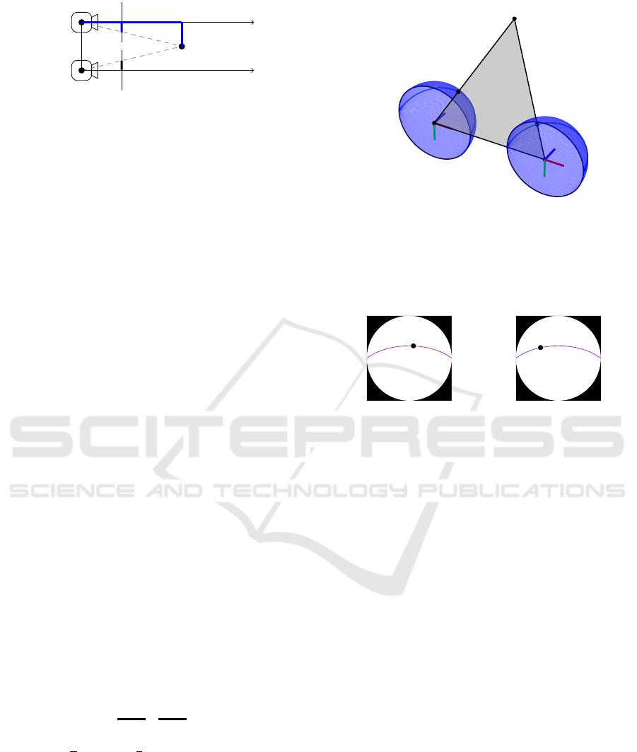
Figure 2: Reconstruction of a point P
P
P in a CCS following
the perspective camera model. The position of the point P
P
P
can be retrieved by mean of similar triangles.
mounted on the ceiling. This large FOV is associ-
ated with image distortions that increases the com-
plexity of the disparity and depth estimation. Similar
to Fig. 1, a stereo setup with omnidirectional cameras
is shown in Fig. 3.
For omnidirectional images, the projection of a
point P
P
P from the camera coordinate system on the im-
ages plane can be modeled using the equidistant pro-
jection model for dioptric cameras of (Kannala and
Brandt, 2006).
In the case of omnidirectional cameras, the point
P
P
P is projected on a hemisphere. We follow the pro-
cess in (Findeisen et al., 2014) and project P
P
P first on
a left and a right virtual hemispherical image. Each
point
˜
P
P
P
0
omni
and
˜
P
P
P
1
omni
on these hemispheres can be
described in terms of polar coordinates, i.e. through
radius r, elevation angle θ and azimuth angle φ.
Before the projection from the hemispheres on the
image planes is performed, a normalized image plane
is defined as follows (Kannala and Brandt, 2006):
x
norm
y
norm
= θ ·
cosφ
sinφ
, (4)
where the focal length of the normalized image
plane is 1 and the origin of coordinates coincides with
the image’s center.
Finally, to obtain the coordinates on the image
plane, an affine transformation with the so-called cal-
ibration matrix K
K
K is applied on the normalized image
of Eq. 4:
x
img
y
img
=
f
x
s c
x
0 f
y
c
y
0 0 1
| {z }
K
K
K
·
x
norm
y
norm
, (5)
where f
x
=
w
π
and f
y
=
h
π
are the image focal lengths,
w and h are the image width and height, respectively,
c
x
and c
y
are the coordinates of the image’s center and
s is the screw coefficient between the image’s x- and
y-axis.
The described omnidirectional model causes that
the points P
P
P
0
omni
and P
P
P
1
omni
(both projections of P
P
P) on
the left and right images no longer are arranged along
P
P
P
˜
P
P
P
0
omni
˜
P
P
P
1
omni
C
C
C
0
C
C
C
1
c
c
c
0
c
c
c
1
Figure 3: Canonical binocular stereo vision setup follow-
ing the omnidirectional camera model. The point P
P
P is
projected on the image hemispheres at position
˜
P
P
P
0
omni
and
˜
P
P
P
1
omni
. In contrast to Fig. 1, the points do not have the
same y-coordinate as they do not lie on epipolar lines but
on epipolar curves c
c
c
0
and c
c
c
1
.
P
P
P
0
omni
(a) C
C
C
0
- omnidirectional
P
P
P
1
omni
(b) C
C
C
1
- omnidirectional
Figure 4: Stereo image planes of the setup in Fig. 3. The
points P
P
P
0
omni
and P
P
P
1
omni
are projected from P
P
P on the left and
right epipolar curves.
a line, as for the perspective camera model, but along
a curve as shown in Fig. 4.
As a consequence, in omnidirectional stereo vi-
sion, the matching point P
P
P
1
omni
for a given point
P
P
P
0
omni
must be searched along a 2D epipolar curve
on the right image. To avoid this problem, some ap-
proaches transform the hemispherical image to a half-
cylindrical image and then project the resulting epipo-
lar curves as lines onto the image plane (Li, 2006;
Findeisen and Hirtz, 2014; Findeisen et al., 2014). Al-
though, this allows to reduce the search domain for
point matching to one dimension, the re-projection
step on a half-cylindrical image introduces interpola-
tion artifacts that affect the disparity map generation.
CNNs appear to have the potential to be able to
learn the geometry of epipolar curves and therefore to
generate disparity maps directly from untransformed
omnidirectional images. In the next section, we de-
scribe AnyNet (Wang et al., 2019), a state-of-the-art
network to generate disparity maps from perspective
images and in Sec. 5 we analyze if its architecture is
also able to learn epipolar curves.
VISAPP 2021 - 16th International Conference on Computer Vision Theory and Applications
812
3.3 Stereo Vision with AnyNet
To study the impact of omnidirectional distortion on
the generation of disparity maps through CNNs, we
have selected AnyNet (Wang et al., 2019).
AnyNet is a recently developed network that has
reached state-of-the-art results on perspective images.
This network has the particularity of predicting suc-
cessive disparity maps while increasing their quality
with each step. In this way, AnyNet achieves a com-
promise between computing time and precision.
AnyNet’s architecture consists of four stages, each
of which offers a disparity map as output and feeds
the next stage with information. Stage one to three
predict the disparity map in different resolutions from
coarse to fine. The forth stage sharpens the dispar-
ity map of the third stage with an SPNet (Liu et al.,
2017).
The stages one to three take feature vectors as an
input, which are calculated from the stereo pair by
using a U-Net (Ronneberger et al., 2015). SPNet in
stage four has, on the other hand, the stereo pair and
the disparity map of stage three as input.
In addition to the feature vectors, the disparity net-
works in stage two and three also take as input the
disparity map from the previous stage and calculate
a residual map that is added to the current disparity
map. In (Wang et al., 2019), AnyNet is trained with
the synthetic dataset Scene Flow (Mayer et al., 2016)
and later fine-tuned with KITTI (Geiger et al., 2012;
Menze and Geiger, 2015). The end-to-end training is
performed on patches of 512 × 256 pixels randomly
cropped from the original images, while the evalua-
tion is done on KITTI’s full size images (1242 × 375
pixels).
4 EXPERIMENTS
We present a dataset similar to THEODORE (Scheck
et al., 2020), called THEOStereo. THEODORE is
a synthetic dataset of images captured from omni-
directional top-view cameras with 180
◦
FOV. This
dataset comes along with segmentation masks but
does not provide depth maps as ground truth. We
incorporate a pair of virtual omnidirectional cameras
in THEODORE’s environment and generate 31, 250
new stereo image pairs of indoor scenes with their
corresponding depth maps.
The two virtual cameras are arranged in a canon-
ical stereo camera setup using an omnidirectional
(equidistant) camera model, i.e., the viewing direc-
tions are aligned and their x-y-planes are coplanar.
The baseline b was 0.3 m. Both virtual cameras are
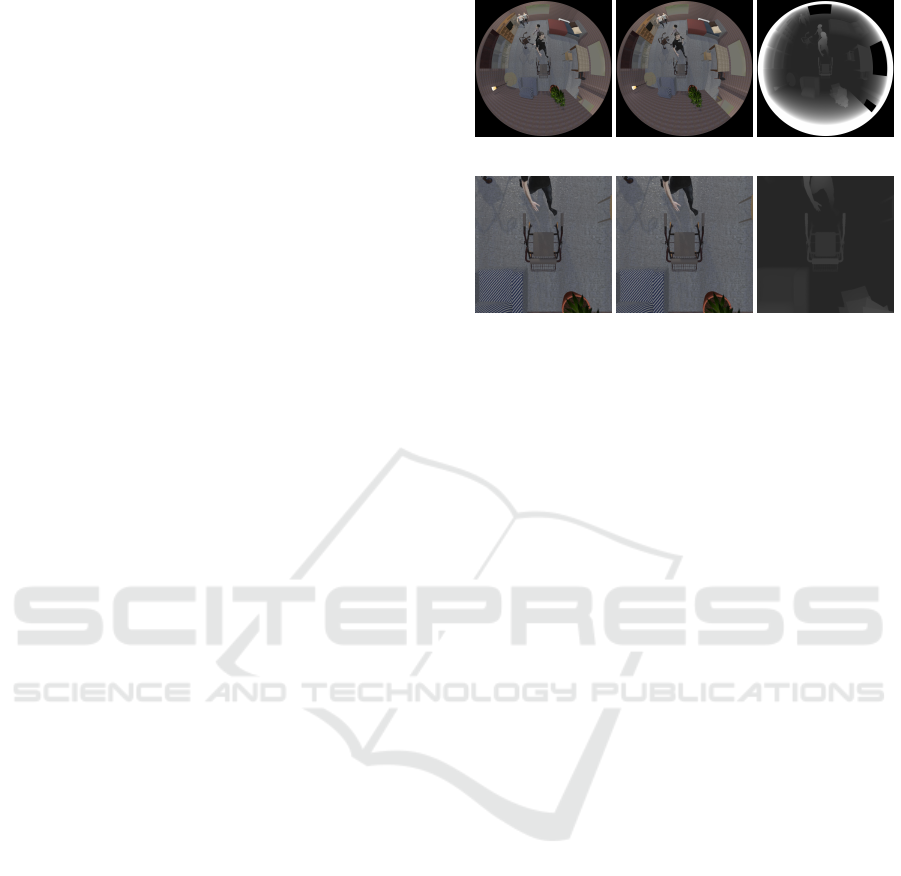
(a) C
C
C
0
− omni. (b) C
C
C
1
− omni. (c) disp. − omni.
(d) C
C
C
0
− persp. (e) C
C
C
1
− persp. (f) disp. − persp.
Figure 5: Sample images of the dataset THEOStereo and
their calculated disparity maps. Their corresponding dis-
parity maps are stored in 16-bit images. For the sake of
visibility, the intensity range of (c) and (f) is clipped at 255.
perfect (perfect hemispherical images) dioptric cam-
eras, which can be described using Kannala’s model
(Kannala and Brandt, 2006) with distortion paramters
k
1
= 1 and k
i
= 0 for i ∈ {2, 3, 4, 5}. The stereo cam-
era height varies between 4.73 m and 5.6 m.
To train AnyNet, we need disparity maps as
ground truth, however THEOStereo provides depth
maps. The values of a depth map depend only on
the height of the scene’s objects and the position of
the camera. Therefore, they are the same for equally
positioned perspective and omnidirectional cameras.
However, as described before, this is not the case
for disparity maps. In the case of perspective stereo,
each value of the disparity map describes a horizontal
translation to the right, whereas for omnidirectional
disparity two values are necessary in order to describe
a translation along an epipolar curve, which would re-
sult in a two-channel disparity map.
In order not to change the architecture of AnyNet,
we generate single-channel disparity maps from the
dataset’s depth maps. THEOStereo’s depth maps
present the same omnidirectional distortion as the in-
put images. In this way, by applying Eq. 3 on these
omnidirectional depth maps, we obtain a hybrid dis-
parity map with values that correspond to a perspec-
tive geometry, but conserving the omnidirectional dis-
tortion on their arrangement (See first row Fig. 5).
We generate a second dataset from THEO-
Stereo by transforming its images to a perspective
view with a typical FOV of 60
◦
. Fig. 5 shows an ex-
ample of a THEOStereo stereo image pair and its per-
spective version, as well as their disparity maps. This
second dataset is used to compare the performance
of AnyNet for perspective and omnidirectional im-
A Study on the Influence of Omnidirectional Distortion on CNN-based Stereo Vision
813

Table 1: Results of AnyNet on THEOStereo. The error refers to the testing subset of THEOStereo after training 200 epochs.
Exp. Camera model Input size in pixels MAE in pixels δ > 1 δ > 2 δ > 4 δ > 3 & ε > 5 %
A perps. 512 × 256 0.33 9.6 % 4.9 % 2.2 % 2.9 %
B omni. 512 × 256 6.36 75.0 % 57.0 % 35.9 % 39.3 %
C omni. 1024 × 1024 3.94 68.8 % 46.8 % 23.4 % 26.4 %
ages. Both datasets are split into three subsets: train-
ing (80%), validation (10%) and testing (10%).
We perform three experiments:
• Exp. A: In this experiment, we use the pre-trained
model of AnyNet with Scene Flow and fine-tuned
it with our perspective dataset. The network is
trained on randomly selected image patches of
512 × 256 pixels (See Sec. 3.3).
• Exp. B: The pre-trained AnyNet is fine-tuned with
randomly selected omnidirectional image patches
of THEOStereo as in Exp. A.
• Exp. C: We repeat experiment B by fine-tuning on
the full omnidirectional images. This experiment
considers global information during the training.
In this way, with each image pair, the network
learns the complete epipolar curves and not a sec-
tion of them as in Exp. B.
For all experiments the evaluation is performed on
the testing dataset considering full images. AnyNet is
trained for all experiments during 200 epochs using
Adam (Kingma and Ba, 2015) with an initial learn-
ing rate of 5 · 10
−4
. We applied cosine annealing
(Loshchilov and Hutter, 2017) to successively reduce
the learning rate to zero until the end of the training.
We chose a batch size of 48 for all experiments and
activated the SPNet in the second epoch.
5 RESULTS
To evaluate the performance of the network in all
three experiments, five error metrics are considered:
Mean Absolute Error, the ratio δ > i of pixels with er-
rors greater than i, with i ∈ {1, 2, 4} and the 3-Pixel-
Error.
The Mean Absolute Error (MAE) is calculated by
taking the mean value of the absolute difference per
pixel between the predicted disparity map and the
ground truth (L
1
loss).
The metric δ > i indicates the percentage of pix-
els in the predicted disparity map that have an error
bigger than i pixels with respect to the ground truth.
The metrics δ > 1, δ > 2 and δ > 4 are the so-called
bad-1, bad-2 and bad-4 error (Scharstein et al., 2014).
The 3-Pixel-Error (Menze and Geiger, 2015) is
defined by δ > 3 & ε > 5%, where δ > 3 indicates
the ratio of pixels with an error bigger than three pix-
els and ε > 5% denotes that such errors are also bigger
than 5% of the ground truth disparity value.
Each considered metric was first averaged batch-
wise for a batch size of 48 and finally averaged over
all batches. Tab. 1 documents the error measurements
for each experiment. As expected, AnyNet hat the
best performance for the case of perspective images
(Exp. A). Experiments B and C present much higher
errors, showing that AnyNet has much more difficulty
in learning from omnidirectional images. However,
as shown later in Fig. 6, it is still able to generate an
omnidirectional disparity map.
The difference between Exp. B and Exp. C shows
that the network can reach better results, when the
complete image is used to train. Learning from the
full images helps the network to understand the om-
nidirectional geometry better.
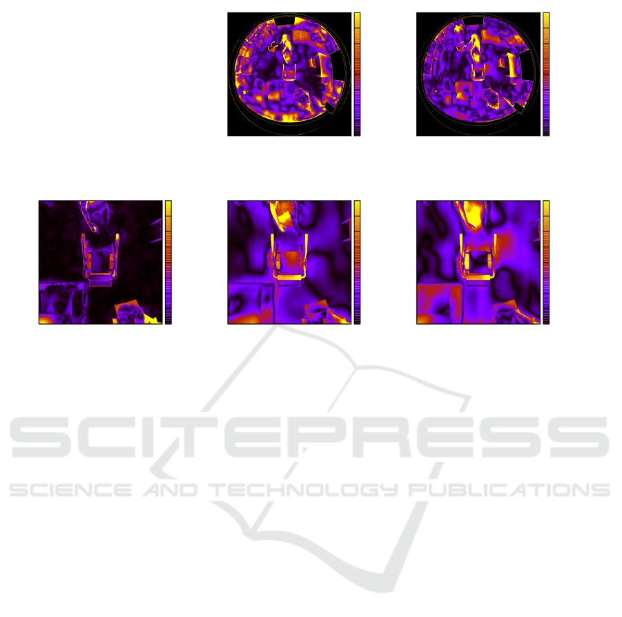
To visualize the error, Fig. 6 shows for all experi-
ments the Absolute Error Heat Map (AE-HM) for an
image of the testing dataset. In the first row, the result-
ing AE-HM of Exp. B and C are presented. We can
see that, while the error in the center of both maps is
similar, the error in Exp. B increases with the distance
to the center. This latter indicates that by learning
from patches, the network losses information about
the global omnidirectional geometry.
The second row in Fig. 6 presents the AE-HM
for Exp. A on the same image. By considering
a perspective camera, the FOV is reduced by two
thirds and the absolute error also reduces consider-
ably. In order to facilitate the comparison, the AE-
HMs of Exp. B and C have been cropped and con-
verted to perspective in such a way that they coincide
with the AE-HM of Exp. A. Areas that correspond
in the ground truth disparity map to a larger dispar-
ity value than AnyNet’s default maximum disparity
(192) are excluded in Fig. 6a to Fig. 6e (set to black).
This comparison shows that for omnidirectional im-
ages, AnyNet does not accurately retrieve the depth
of planes such as the floor, but is almost error-free in
the case of perspective images.
VISAPP 2021 - 16th International Conference on Computer Vision Theory and Applications
814
data using 2:1:3
0
2
4
6
8
10
12
14
16
(a) omni. - training on 512 × 256
Exp. B
data using 2:1:3
0
2
4
6
8
10
12
14
16
(b) omni. - training on 1024 × 1024
Exp. C
data using 2:1:3
0
2
4
6
8
10
12
14
16
(c) persp. - training on 512 × 256
Exp. A
data using 2:1:3
0
2
4
6
8
10
12
14
16
(d) omni. - training on 512 × 256
(undistorted)
data using 2:1:3
0
2
4
6
8
10
12
14
16
(e) omni. - training on 1024 × 1024
(undistorted)
Figure 6: Absolute Error Heat Maps of a sample testing image. In the top row, the training was performed on cropped and
full size omnidirectional images. The AE-HM generated by training the network on the perspective image patches is shown
in (c). The Figs. (d) and (e) show the same heat maps of (a) and (b) but converted to perspective with the same FOV as (c).
The color range visualizes a mean absolute error between 0 and 16 pixels.
6 CONCLUSION AND FUTURE
WORK
In this work, we compare the quality of disparity
maps predicted from perspective and omnidirectional
stereo images. For this study, we train AnyNet on
our dataset THEOStereo. We demonstrate that it is
possible to learn disparity maps from omnidirectional
images, which allow wide angle 3D scene reconstruc-
tions. Furthermore, we prove that by learning from
omnidirectional images, global information is essen-
tial as it can significantly reduce the MAE by around
35 %. A comparison of our approach with approaches
like OmniMVS (Won et al., 2019a) are planned. Fu-
ture experiments will also investigate other loss func-
tions, metrics and networks. Instead of single chan-
nel disparity maps, the utilization of multichannel
maps encoding an n-dimensional disparity metric or
feature vector should be investigated. For that pur-
pose, the architecture of the disparity networks must
be adapted. With our dataset, we pave the way for
further research on omnidirectional stereo vision with
aligned cameras.
ACKNOWLEDGEMENTS
This work is funded by the European Regional De-
velopment Fund (ERDF) as well as the Free State of
Saxony under the grant number 100-241-945.
REFERENCES
Chang, J.-R. and Chen, Y.-S. (2018). Pyramid Stereo
Matching Network. In 2018 IEEE/CVF Conference
on Computer Vision and Pattern Recognition, pages
5410–5418, Salt Lake City, UT. IEEE.
Findeisen, M. and Hirtz, G. (2014). Trinocular Spheri-
cal Stereo Vision for Indoor Surveillance. In 2014
Canadian Conference on Computer and Robot Vision,
pages 364–370, Montreal, QC, Canada. IEEE.
Findeisen, M., Meinel, L., and Hirtz, G. (2014). A
trinocular omnidirectional stereo vision system for
high-precision RGB-D acquisition. In Proceedings
ELMAR-2014, pages 1–4, Zadar, Croatia. IEEE.
Geiger, A., Lenz, P., and Urtasun, R. (2012). Are we ready
for autonomous driving? The KITTI vision bench-
mark suite. In 2012 IEEE Conference on Computer
Vision and Pattern Recognition, pages 3354–3361,
Providence, RI. IEEE.
A Study on the Influence of Omnidirectional Distortion on CNN-based Stereo Vision
815

Giancola, S., Valenti, M., and Sala, R. (2018). A Survey
on 3D Cameras: Metrological Comparison of Time-
of-Flight, Structured-Light and Active Stereoscopy
Technologies. SpringerBriefs in Computer Science.
Springer International Publishing, Cham, 1 edition.
Hartley, R. and Zisserman, A. (2004). Multiple View Geom-
etry in Computer Vision. Cambridge University Press,
Cambridge, UK, 2 edition. https://doi.org/10.1017.
Hirschm
¨
uller, H. (2008). Stereo Processing by Semiglobal
Matching and Mutual Information. IEEE Transac-
tions on Pattern Analysis and Machine Intelligence,
30(2):328–341.
Kannala, J. and Brandt, S. S. (2006). A generic camera
model and calibration method for conventional, wide-
angle, and fish-eye lenses. IEEE Transactions on Pat-
tern Analysis and Machine Intelligence, 28(8):1335–
1340. Conference Name: IEEE Transactions on Pat-
tern Analysis and Machine Intelligence.
Kendall, A., Martirosyan, H., Dasgupta, S., Henry, P.,
Kennedy, R., Bachrach, A., and Bry, A. (2017). End-
to-End Learning of Geometry and Context for Deep
Stereo Regression. In 2017 IEEE International Con-
ference on Computer Vision (ICCV), pages 66–75,
Venice. IEEE.
Kingma, D. P. and Ba, J. (2015). Adam: A Method for
Stochastic Optimization. In Bengio, Y. and LeCun,
Y., editors, 3rd International Conference on Learn-
ing Representations, ICLR 2015, San Diego, CA, USA,
May 7-9, 2015, Conference Track Proceedings.
Li, S. (2006). Trinocular Spherical Stereo. In 2006
IEEE/RSJ International Conference on Intelligent
Robots and Systems, pages 4786–4791, Beijing,
China.
Liu, S., De Mello, S., Gu, J., Zhong, G., Yang, M.-H., and
Kautz, J. (2017). Learning Affinity via Spatial Propa-
gation Networks. In Guyon, I., Luxburg, U. V., Ben-
gio, S., Wallach, H., Fergus, R., Vishwanathan, S., and
Garnett, R., editors, Advances in Neural Information
Processing Systems 30, pages 1520–1530. Curran As-
sociates, Inc.
Loshchilov, I. and Hutter, F. (2017). SGDR: Stochastic Gra-
dient Descent with Warm Restarts. In 5th Interna-
tional Conference on Learning Representations, ICLR
2017, Toulon, France, April 24-26, 2017, Conference
Track Proceedings. OpenReview.net.
Luo, W., Schwing, A. G., and Urtasun, R. (2016). Efficient
Deep Learning for Stereo Matching. In 2016 IEEE
Conference on Computer Vision and Pattern Recogni-
tion (CVPR), pages 5695–5703, Las Vegas, NV, USA.
IEEE.
Mayer, N., Ilg, E., Hausser, P., Fischer, P., Cremers, D.,
Dosovitskiy, A., and Brox, T. (2016). A Large Dataset
to Train Convolutional Networks for Disparity, Opti-
cal Flow, and Scene Flow Estimation. In 2016 IEEE
Conference on Computer Vision and Pattern Recogni-
tion (CVPR), pages 4040–4048, Las Vegas, NV, USA.
IEEE.
Menze, M. and Geiger, A. (2015). Object scene flow for
autonomous vehicles. In 2015 IEEE Conference on
Computer Vision and Pattern Recognition (CVPR),
pages 3061–3070, Boston, MA, USA. IEEE.
Ronneberger, O., Fischer, P., and Brox, T. (2015). U-Net:
Convolutional Networks for Biomedical Image Seg-
mentation. pages 234–241. Springer, Cham.
Scharstein, D., Hirschm
¨
uller, H., Kitajima, Y., Krath-
wohl, G., Ne
ˇ
si
´
c, N., Wang, X., and Westling,
P. (2014). High-Resolution Stereo Datasets with
Subpixel-Accurate Ground Truth. volume 8753, pages
31–42, Cham. Springer. Series Title: Lecture Notes in
Computer Science.
Scharstein, D., Szeliski, R., and Zabih, R. (2001). A
taxonomy and evaluation of dense two-frame stereo
correspondence algorithms. In Proceedings IEEE
Workshop on Stereo and Multi-Baseline Vision (SMBV
2001), pages 131–140, Kauai, HI, USA. IEEE Com-
put. Soc.
Scheck, T., Seidel, R., and Hirtz, G. (2020). Learning from
theodore: A synthetic omnidirectional top-view in-
door dataset for deep transfer learning. In Proceedings
of the IEEE/CVF Winter Conference on Applications
of Computer Vision (WACV).
ˇ
Zbontar, J. and LeCun, Y. (2016). Stereo matching by train-
ing a convolutional neural network to compare image
patches. J. Mach. Learn. Res., 17(1):2287–2318.
Wang, Y., Lai, Z., Huang, G., Wang, B. H., van der Maaten,
L., Campbell, M., and Weinberger, K. Q. (2019). Any-
time Stereo Image Depth Estimation on Mobile De-
vices. In 2019 International Conference on Robotics
and Automation (ICRA), pages 5893–5900, Montreal,
QC, Canada. IEEE.
Won, C., Ryu, J., and Lim, J. (2019a). OmniMVS: End-to-
End Learning for Omnidirectional Stereo Matching.
In 2019 IEEE/CVF International Conference on Com-
puter Vision (ICCV), pages 8986–8995, Seoul, Korea
(South). IEEE.
Won, C., Ryu, J., and Lim, J. (2019b). SweepNet: Wide-
baseline Omnidirectional Depth Estimation. In 2019
International Conference on Robotics and Automation
(ICRA), pages 6073–6079, Montreal, QC, Canada.
IEEE.
Won, C., Ryu, J., and Lim, J. (2020). End-to-End Learn-
ing for Omnidirectional Stereo Matching with Uncer-
tainty Prior. IEEE Transactions on Pattern Analysis
and Machine Intelligence. Early Access.
VISAPP 2021 - 16th International Conference on Computer Vision Theory and Applications
816
