
A Framework for Projectional Multi-variant Model Editors
Johannes Schr
¨
opfer, Thomas Buchmann and Bernhard Westfechtel
Chair of Applied Computer Science I, University of Bayreuth, Universit
¨
atsstrasse 30, 95440 Bayreuth, Germany
Keywords:
Model-driven Development, Software Product Lines, Multi-variant Model, Projectional Editing, ALF, Ecore,
Syntax-directed Editor, Generic Framework.
Abstract:
Model-driven software product line engineering (MDSPLE) combines the productivity gains achieved by
model-driven software engineering and software product line engineering. In MDSPLE, multi-variant models
are created in domain engineering which are configured into single-variant models that are adapted further (if
required) in application engineering. Since multi-variant models are inherently complex, tools are urgently
needed which provide specific support for editing multi-variant models. In this paper, we present a framework
for projectional multi-variant editors which do not hide complexity but make it manageable by a user-friendly
representation. At all times, a domain engineer is aware of editing a multi-variant model which is necessary to
assess the impact of changes on all model variants. Projectional multi-variant editors provide a novel approach
to representing variability information which is displayed non-intrusively and supports a clear separation of
the product space (the domain model) from the variant space (variability annotations). Furthermore, the do-
main engineer may employ a projectional multi-variant editor to adapt the representation of the multi-variant
domain model in a flexible way, according to the current focus of interest.
1 INTRODUCTION
After having explained the context of our research
(Section 1.1), we summarize the contribution of this
paper (Section 1.2). Finally, we provide an overview
of the rest of this paper (Section 1.3).
1.1 Context
In model-driven software engineering (MDSE)
(V
¨
olter et al., 2006), software systems are developed
by creating high-level models which are analyzed,
simulated, executed, or transformed into code. In this
context, models are structured artifacts which are in-
stantiated from metamodels. A metamodel defines the
types of elements from which models are composed
and the rules for their composition. For metamodels,
the Object Management Group (OMG) has defined
the MOF standard (Meta Object Facility), a subset of
which is implemented as Ecore in the Eclipse Model-
ing Framework (EMF) (Steinberg et al., 2009).
Models may be represented in a variety of differ-
ent ways, including diagrams, trees, tables, or human-
readable text. Different kinds of editors may be em-
ployed to create and modify models. In the case of a
textual representation, a syntax-based editor may be
used which persists the text and derives the underly-
ing model by an incremental parsing process. In the
EMF ecosystem, the Xtext
1
framework is frequently
used to generate syntax-based editors from language
descriptions.
In contrast, projectional editors provide for com-
mands operating directly on the model and project
the model onto a suitable representation (V
¨
olter et al.,
2014). A projectional editor may ensure syntactic cor-
rectness of models and enjoys further advantages con-
cerning tool integration. In particular, since models
are stored as instances of metamodels, unique iden-
tifiers may be assigned to model elements such that
they may be referenced in a reliable way.
Software product line engineering (SPLE) (Pohl
et al., 2005) is a discipline which is concerned with
the systematic development of families of software
systems from reusable assets. To this end, common
and discriminating features of family members are
captured in a variability model, e.g., a feature model
(Kang et al., 1990). In domain engineering, a variabil-
ity model is developed along with a set of reusable as-
sets. In application engineering, product variants are
developed from reusable assets.
Product variants may be constructed in different
1
https://www.eclipse.org/Xtext
294
Schröpfer, J., Buchmann, T. and Westfechtel, B.
A Framework for Projectional Multi-variant Model Editors.
DOI: 10.5220/0010310102940305
In Proceedings of the 9th International Conference on Model-Driven Engineering and Software Development (MODELSWARD 2021), pages 294-305
ISBN: 978-989-758-487-9
Copyright
c
2021 by SCITEPRESS – Science and Technology Publications, Lda. All rights reserved

ways. In case of positive variability, they are com-
posed from reusable modules. In case of transforma-
tional variability, product variants are constructed by
applying a sequence of transformations. In case of
negative variability, multi-variant artifacts are rep-
resented as superimpositions of annotated elements.
An annotation constitutes a presence condition over
features. A product variant is defined by a feature
configuration, stating which features have to be in-
cluded and excluded, respectively. To construct a
single-variant artifact, all elements are removed from
a multi-variant artifact whose annotations evaluate to
false.
Model-driven software product line engineering
(MDSPLE) combines MDSE with SPLE. Thus, SPLE
is applied to models. While most SPLE approaches
focus on source code rather than models, a num-
ber of MDSPLE tools have been developed, e.g.,
FeatureMapper (Heidenreich et al., 2008), FAMILE
(Buchmann and Schw
¨
agerl, 2012), and SuperMod
(Schw
¨
agerl and Westfechtel, 2019) all of which are
based on EMF.
1.2 Contribution
This paper presents a framework for generating pro-
jectional multi-variant model editors. This frame-
work is based on our previous work on projectional
single-variant editors for models in the technologi-
cal space of EMF. As described in (Schr
¨
opfer et al.,
2020), a projectional editor may be generated from a
metamodel for domain models (an Ecore model defin-
ing classes, attributes, and references) and a syntax
definition which maps model elements to a human-
readable textual representation. In the work pre-
sented in this paper, we have extended the frame-
work for single-variant model editors into a frame-
work for building multi-variant editors. This exten-
sion is generic, i.e., it depends neither on the under-
lying metamodel nor on the syntax definition. Thus,
no additional development effort is required to turn a
single-variant editor into a multi-variant editor.
A projectional multi-variant editor which has been
built with the help of our framework is characterized
by the following properties:
1. So far, our projectional editors support human-
readable text as the external representation of
EMF models. In MDSE, human-readable text is
becoming increasingly popular which is substan-
tiated, e.g., by the definition of UML-based tex-
tual languages such as the Action Language for
Foundational UML (ALF) (OMG, 2017). The ed-
itor’s design is extensible; further representations
such as diagrams may be added in the future.
2. Projectional multi-variant editors are based on
negative variability (probably the main-stream
SPLE approach). Thus, engineers do not have to
learn new languages. Rather, domain models are
augmented with annotations.
3. For modeling variability, feature models (the most
widespread notation in SPLE) are used. All anno-
tations refer to features and attributes from a fea-
ture model for the software product line.
4. Projectional multi-variant editors are designed to
support domain engineering. Since multi-variant
models are the artifacts of domain engineering, a
projectional multi-variant editor directly operates
on a multi-variant model. Thus, all variants may
be considered by the domain engineer during edit-
ing. Furthermore, each command has a uniquely
determined semantics. These properties distin-
guish our approach from variation control systems
which are faced with view-update problems and
limited awareness in filtered views.
5. Internally, annotations of model elements are
stored in a separate mapping model. Thus, exist-
ing domain metamodels may be reused. Further-
more, the relationships between features in the
feature model and elements of domain models are
captured in one single central data structure. This
approach facilitates traceability and propagation
of changes from the feature model to annotated
domain models.
6. The mapping model is shielded from the user.
Rather, annotations are displayed intuitively along
with the model elements in a single representa-
tion. Therefore, the user does not have to deal
with the internal concepts and structure of the
mapping model. In contrast to approaches based
on preprocessor directives, annotations are sepa-
rated clearly from domain model elements in the
representation of a multi-variant model.
7. Projectional multi-variant editors include com-
mands for projectional editing of annotations.
Thus, annotations are handled as structured ob-
jects rather than as text strings. Context-free cor-
rectness of annotations is guaranteed by the pro-
jectional editor.
8. To cope with complexity, projectional multi-
variant editors provide several commands for
adapting the representation of an annotated
model to the current focus of interest. For ex-
ample, annotations may be hidden completely or
selectively. In this way, the representation of the
model may be simplified. It should be noted, how-
ever, that all editing commands still refer to the
underlying multi-variant model.
A Framework for Projectional Multi-variant Model Editors
295

1.3 Overview
The rest of this paper is structured as follows: Sec-
tion 2 explains the background of our research and re-
lated work. Section 3 describes the functionality and
the user interface of projectional multi-variant editors.
Section 4 outlines the model-based internal architec-
ture underlying these editors. Section 5 details a spe-
cific aspect of the realization: the mapping between
domain models and feature models. Finally, Section 6
concludes the paper.
2 BACKGROUND AND RELATED
WORK
As stated above, software product line engineering
fosters organized reuse to create a set of software ar-
tifacts from which single applications sharing com-
mon features may be (automatically) derived. In or-
der to be successful, a special development process is
required which contains two phases: (1) domain en-
gineering (DE) and (2) application engineering (AE)
(Pohl et al., 2005). Domain engineering covers cap-
turing and implementing common and variable as-
pects of the software system, e.g., in a variability
model and implementation artifacts. The variabil-
ity model and the corresponding implementation ar-
tifacts form the platform of the software product line.
Throughout the years, feature models (Kang et al.,
1990) have become a de facto standard for models
capturing the variability of a software product line.
A feature model uses features as boolean proper-
ties of a software system which can be either present
or absent in a specific product. Features are arranged
in an and/or tree. Each feature is either mandatory
or optional. If a child feature is selected, the respec-
tive parent feature has to be selected, as well. Addi-
tionally, groups of alternative features are provided,
exactly one member of which has to be selected, re-
spectively. Depending on the respective variant of
feature models, refining modeling constructs are pro-
vided, such as requires and excludes relationships
(Schobbens et al., 2006).
Application engineering deals with the construc-
tion of product variants from the reusable assets de-
veloped in domain engineering. Basically, three dif-
ferent approaches exist to construct products: (1) In
approaches based upon positive variability, product-
specific artifacts are built around a common core.
Composition techniques (Apel et al., 2009) are used
to finally derive products. (2) In case of transfor-
mational variability (Schaefer, 2018), a sequence of
transformations is performed to construct products,
while (3) in approaches based on negative variability
(Apel and K
¨
astner, 2009; Buchmann and Schw
¨
agerl,
2012), a superimposition of all variants is created in
the form of a multi-variant product. The derivation
of products is realized by removing all fragments of
artifacts implementing features not contained in the
desired product.
In all three cases, the application engineer binds
the variability by creating a feature configuration. In
a feature configuration, a selection state (selected or
deselected) is assigned to each feature variable. A fea-
ture configuration is consistent if the provided selec-
tions conform to the constraints defined in the feature
model.
Negative variability extends single- to multi-
variant artifacts by annotating artifact elements. In
contrast to positive and transformational variabil-
ity, the languages for single-variant artifacts may be
reused. Thus, SPLE engineers do not have to learn
new languages. However, editing multi-variant arti-
facts poses a significant cognitive challenge. For ex-
ample, editing source code written in the program-
ming language C turns out to be difficult because pre-
processor directives realizing annotations are inter-
mingled with ordinary C code.
Therefore, dedicated multi-variant editors are re-
quired for making the complexity manageable. To
date, quite a number of rather different approaches
have been proposed and implemented. All of these
approaches suffer from different shortcomings:
• Virtual separation of concerns (Apel and K
¨
astner,
2009) applies C-like preprocessor directives to
Java code; separation of concerns is supported
in a syntax-based editor by assigning colors to
features and by eliding deselected program frag-
ments. Coloring works only for a small set of
features; furthermore, preprocessor directives are
still intermingled with ordinary code, i.e., two
different aspects of the software product line are
mixed in one physical resource. In addition, as
soon as a product is derived, the traceability links
between features and code are lost.
• Model-driven tools such as FeatureMapper (Hei-
denreich et al., 2008) and FAMILE (Buchmann
and Schw
¨
agerl, 2012) follow a different approach:
Annotations are stored and visualized in a dedi-
cated mapping model. While annotations are sep-
arated from models, the SPLE engineer is exposed
to an internal data structure which should be hid-
den from the user. Furthermore, it is hard to
understand the relationships between model ele-
ments and annotations. Eventually, the mentioned
tools support domain engineering only. As soon
as a product is derived, the connection to the plat-
MODELSWARD 2021 - 9th International Conference on Model-Driven Engineering and Software Development
296
form of the product line is lost.
• In contrast to the approaches having been dis-
cussed above, variation control systems reduce
complexity by filtered editing (Linsbauer et al.,
2021). From a multi-variant artifact called source,
a view is materialized in which variability has
been resolved completely or partially. After edit-
ing of the view has been finished, the performed
changes are propagated back to the source. Varia-
tion control systems are faced with two problems:
Limited awareness of the context in which editing
is performed and delineation of the scope of the
change in the variant space. While the other tools
mentioned above primarily display and edit arti-
facts of domain engineering, and provide (filtered)
views of the multi-variant domain model, varia-
tion control systems operate on (partially config-
ured) products. Thus, the software product line
engineer works on specific variants (as in applica-
tion engineering) and domain engineering is per-
formed implicitly when a commit into the version
repository is executed.
In contrast to the approaches mentioned above, our
approach completely hides the mapping model from
the user. The SPL engineer is empowered to use fea-
ture annotations in the concrete syntax in an intuitive
way. Furthermore, the annotations may be hidden in
the editor at any time. Sophisticated visualizations
allow for different views of the multi-variant domain
model ranging from fine-grained views showing sin-
gle features only, over partial feature configurations to
a view on the complete multi-variant domain model.
In our approach, application engineering is a fully
automated process where the final products are de-
rived from the multi-variant domain model using a
feature configuration. The derived artifacts comprise
traceability links to the multi-variant domain model to
support evolution.
In (Mukelabai et al., 2018) the authors present a
multi-view projectional editor for software product
lines based on JetBrains MPS
2
. In contrast to our ap-
proach which is generic and allows for reusing ex-
isting EMF technology (modeling languages, model
transformations, code generators), the PEoPL solu-
tion focuses on combining annotative and composi-
tional editing of software product lines for a specific
modeling language.
2
https://www.jetbrains.com/mps/
3 FUNCTIONALITY AND USER
INTERFACE
This section describes the functionality of the projec-
tional editor framework by outlining an example use
case. In general, the multi-variant editor may be gen-
erated for an arbitrary domain model (or an appropri-
ate subtree) that is an instance of an arbitrary meta-
model. For the example scenario, a projectional ed-
itor for the textual modeling language ALF has been
generated; the language ALF (Action Language for
Foundational UML) (OMG, 2017) provides a concise
textual syntax for Foundational UML (fUML) (OMG,
2020), a subset of UML enriched with precise execu-
tion semantics. In the editor, a graph library product
line is modeled which constitutes a common example
in SPL literature (Lopez-Herrejon and Batory, 2001;
Schw
¨
agerl et al., 2015).
3.1 The Framework in General
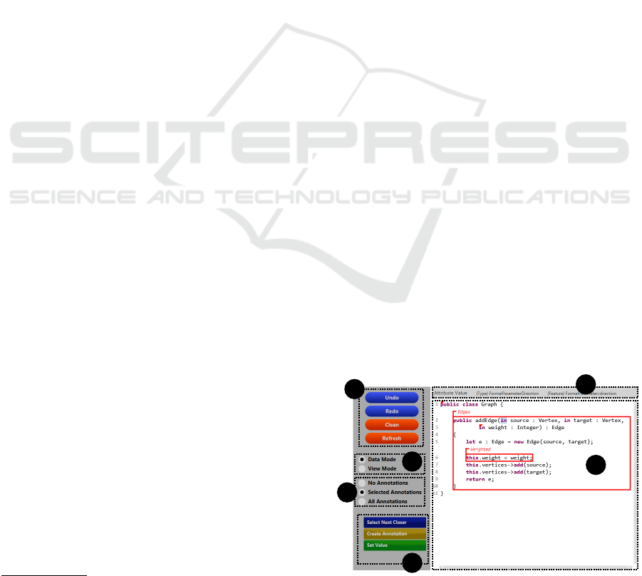
Figure 1 shows a screenshot of the full editor. The
main pane constitutes the major part of the user in-
terface (cf. part 1); it presents the representation
of the underlying abstract syntax (sub-)tree as well
as the corresponding annotations. Above the main
pane, brief information regarding selected elements
is displayed (cf. part 2). The editor provides several
modes. Besides buttons for mode-independent com-
mands (cf. part 3), e.g., the common editor operations
Undo and Redo, mode-specific buttons (cf. part 4),
e.g, commands for inserting elements into the domain
model, can be executed.
With respect to the range of commands, the edi-
tor differentiates two modes (cf. part 5). The data
mode offers commands for editing the domain model.
Data commands perform modifications of the abstract
syntax tree which are propagated to the representation
model. The view mode supports view-specific repre-
1
2
3
4
5
6
Figure 1: The editor user interface for an example use case.
A Framework for Projectional Multi-variant Model Editors
297
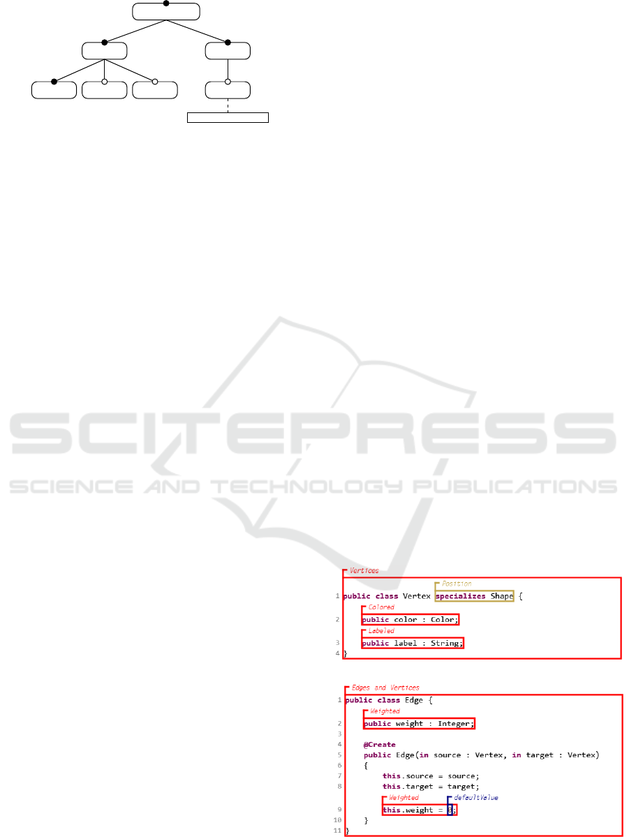
GraphLibrary
Vertices
Position Colored Labeled
Edges
Weighted
defaultValue : INTEGER
Figure 2: Feature model for the use case in graphical no-
tation. Rectangles with rounded corners represent fea-
tures while ordinary rectangles stand for feature attributes.
Mandatory features are tagged by means of filled circles.
sentation commands as adding line breaks or whites-
paces. View commands only affect the representation
model. Since the editor framework not only persists
the domain model but also the representation, custom
layout information is stored after the editor has been
closed.
In addition, three modes are present that refer to
the visibility of annotations (cf. part 6). The do-
main engineer may choose whether no annotations
are visible – without any annotation commands at all
–, whether all annotations are visible, or whether only
a subset of all annotations (selected annotations) are
visualized, e.g., annotations that are relevant for a cer-
tain feature configuration. In the latter case, annota-
tions can be individually visualized and hidden; hid-
den ones are marked by means of a corner triangle
which can be clicked in order to display the respec-
tive annotation again. These three modes are orthog-
onal to the two modes described before; therefore, six
combinations of modes are provided.
The feature model itself is not visualized by the
editor. Currently, the generic EMF tree editor is used.
Future work will provide for a specific projectional
feature model editor with a human-readable textual
syntax. To this end, we will apply our framework to a
metamodel for feature models. By means of this boot-
strapping strategy, we minimize the number of depen-
dencies to other tools. For the example scenario used
in this paper, we assume the feature model graphically
shown in Figure 2. The root feature GraphLibrary con-
tains the mandatory features Vertices and Edges. The
feature Vertices has the mandatory child feature Po-
sition and the optional features Colored and Labeled.
The feature Edges exhibits the optional child feature
Weighted that possesses an integer attribute named
defaultValue.
3.2 Support for Domain Engineering
In general, each representation visualized by the edi-
tor shows exactly one subtree of a domain model. Fur-
thermore, for one domain model, several representa-
tion models may be present each of which refers to
another subtree. Finally, a product line may comprise
several domain models. Therefore, the editors pro-
vide different views of a range of domain models. For
the illustrated use case, there is exactly one domain
model. The model contains an ALF package with
several classes, associations, and a data type. Each
representation model shows an ALF class. Therefore,
for each class, an own editor view is present – analo-
gously to Java classes, for instance.
The editor depicted in Figure 1 shows the repre-
sentation of the ALF class Graph with selected anno-
tations two of which are completely visible and two
are hidden – the annotation binding the whole class
to the feature GraphLibrary and the one for the third
operation parameter referring to the feature Weighted.
For the sake of readability, annotations are depicted as
labels which have specific colors and are located be-
tween the physical lines of the actual domain model
representation. The representation area of the respec-
tively annotated elements is marked by a border line.
Annotations can contain links to features and their
attributes as atoms within boolean expressions pro-
viding common logical operators (conjunction, ex-
and inclusive disjunction, negation). Elements are
modified by projectional commands for adding and
removing objects, restructuring expressions, and set-
ting links. One physical line may also comprise more
than one annotation; their representations are ordered
by employing a layout mechanism that avoids over-
lapping (by moving the labels).
The editor supports several kinds of annotations
depending on the domain model element that is anno-
tated. All kinds of annotations are visible in Figure 3;
Figure 3: Further multi-variant model elements of the ex-
ample use case.
MODELSWARD 2021 - 9th International Conference on Model-Driven Engineering and Software Development
298

for different kinds of annotations, different colors are
used. The framework employs the following classifi-
cation of domain artifacts that can be annotated:
• Visibilities of Objects or Values. The respective
object or value is annotated with a boolean expres-
sion that indicates whether for a given feature con-
figuration, the respective domain model element
is present in the derived product. In the graph li-
brary example, the class Vertex as well as the con-
tained properties color and label (cf. lines 2 f.) are
annotated this way.
• Visibilities of Optional Elements. Optional model
elements – that may comprise numerous different
model artifacts as objects, links, values, or key-
words – are annotated with a boolean expression
that indicates whether for a given feature config-
uration, the respective optional part of the model
is present in the derived product. The ALF class
Vertex inherits from the class Shape – providing
properties for the position coordinates of shapes
within a diagram (not shown in the figure). This
relationship is bound to the annotation Position by
annotating the optional structural feature for gen-
eralizations of classifiers (cf. line 1).
• Elementary Values of Attributes. In addition to
visibilities, values can be annotated with annota-
tions employing feature attributes (from the fea-
ture model). In the multi-variant model, the de-
fault value is stored depending on the concrete at-
tribute type (e.g., 0 for integer attributes). When a
certain product is derived, the values for the fea-
ture attributes are specified within the course of
the feature configuration. In the graph library ex-
ample, the initial value for the property weight in
the class Edge is derived from the feature attribute
defaultValue (cf. line 9).
In case of visibility annotations, the principle of top-
down propagation of annotations is applied. There-
fore, an annotated element is visible if and only if
its annotation evaluates to true and all transitive con-
tainer elements are visible, as well.
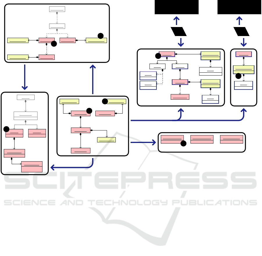
4 ARCHITECTURE
This section outlines the underlying architecture of
the framework and describes the involved system of
models for an example use case. We state the assump-
tion that each product line bases upon one global fea-
ture model. The product line comprises a set of mod-
els which are instances of arbitrary, possibly differ-
ent metamodels based on EMF. Furthermore, the con-
nections between domain model elements and annota-
tions are persisted within one global mapping model.
Analogously, one global correspondence model cap-
tures the internal editor structure.
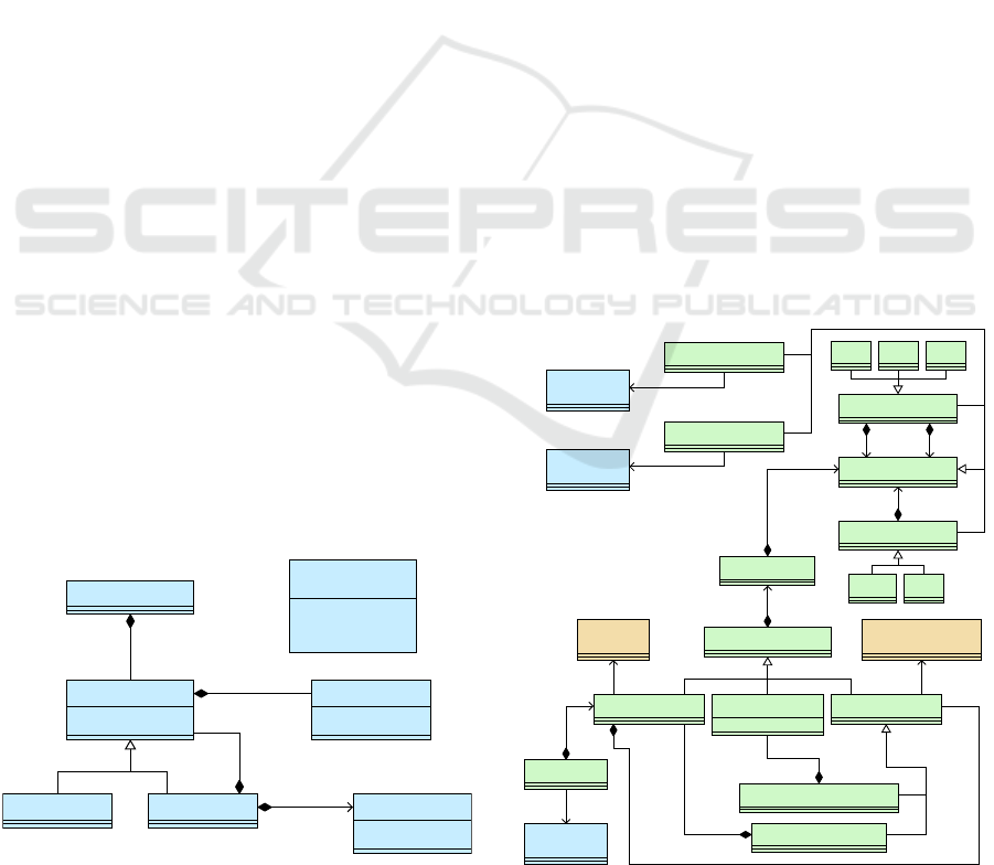
4.1 Overview
Figure 4 shows the architecture that illustrates editors
and models as well as their dependencies. As the tool
context is the Eclipse Modeling Framework, all mod-
els are based on the ECORE metamodel. The editor
including product line support (PL-EDITOR) is an ex-
tension of the projectional editor without product line
context (EDITOR) (Schr
¨
opfer et al., 2020). An edi-
tor instance refers to exactly one abstract syntax tree
(AST) and visualizes either the complete model or a
subtree. The framework does not state any assump-
tions about the metamodel of the abstract syntax tree
(AST
M
).
The mappings from domain model elements to
annotations are stored in the (product line) map-
ping model PL-MAPP. The mapping model comprises
mapping elements for domain model elements of sev-
eral abstract syntax trees. For each annotation, the
mapping element for the respective domain model el-
ement contains a subtree that constitutes the respec-
tive logical expression referencing the feature model
(FEAT); see Section 5 for details about feature model
and mappings. The metamodels FEAT
M
and PL-
MAPP
M
are generic and fixed for arbitrary domain
metamodels. The feature model is modified by using
an extra editor (FEAT-EDITOR). Currently, the default
tree editor provided by EMF is used; future work will
deal with a more comfortable and powerful editor in-
cluding consistency and satisfiability checking.
The correspondence model (CORR) serves as the
central data structure of the editor. It connects the ab-
stract syntax trees, the representation models (REPR),
and the concrete syntax definition model (CSYN).
Furthermore, in case of the extended editor, each edi-
tor correspondence model is linked to a specific prod-
uct line mapping model and vice versa; therefore, in-
ternal editor correspondences and product line map-
pings are conceptually and physically separated. The
correspondence metamodel CORR
M
, the representa-
tion metamodel REPR
M
, as well as the metamodel for
the syntax definition models CSYN
M
are fixed. In case
of the extended editor including product line support,
the representation model also contains elements for
annotations and their contents and the correspondence
model provides respective mappings for expressions
within annotations.
Each editor instance corresponds to one repre-
sentation model. The representation model consists
of model elements for blocks, lines, and cells. For
A Framework for Projectional Multi-variant Model Editors
299
Product Line
Context
Editor Context
FEAT-EDITOR PL-EDITOR
EDITOR
CSYN-EDITOR
UI-MAPP
FEAT
M
PL-MAPP
M
FEAT
PL-MAPP
AST
AST
M
ECORE
CORR REPR
CSYN
CORR
M
REPR
M
CSYN
M
[1]
[1]
[?]
[*]
[1]
[?]
[1]
[*]
[1]
[*]
[1]
[1]
[1]
[*]
[1]
[1]
[1]
[1]
[1]
[1]
[*]
[1]
[*]
[1]
[*]
[1]
[1]
[1]
[1] [1]
[1]
[1]
Tool editor (user interface)
Variable model (persisted)
Fixed model (persisted)
Transient data structure
References
Is instance of
Extends
Modifies
Figure 4: Megamodel describing the architecture elements within one product line and their relations. For References and
Modifies dependencies, the UML multiplicities [1] (exactly one element) and [*] (arbitrarily many elements) are used; the
multiplicity [?] describes optional single elements (in UML 0..1) depending on the fact whether the extended editor is used
(with product line context) or not.
the abstract model elements, the editor pane visu-
alizes concrete geometrical shapes (rectangles and
labels). The traces between representation (REPR
model) and presentation elements (EDITOR user in-
terface) are captured by an internal, transient data
structure (UI-MAPP) which is not persisted when the
editor is closed. The concrete syntax definition model
CSYN is built from projection rules which are spec-
ified by the DSL developer using an extra editor
(CSYN-EDITOR).
All in all, this architecture facilitates a flexible
information exchange between the involved models.
For a given representation element, the editor detects
the respective internal correspondence element in or-
der to access the represented domain model element,
the respective product line mapping element (if any)
as well as the applied projection rule. The intercon-
nected system of models establishes the basis for the
functionality of the different editor commands.
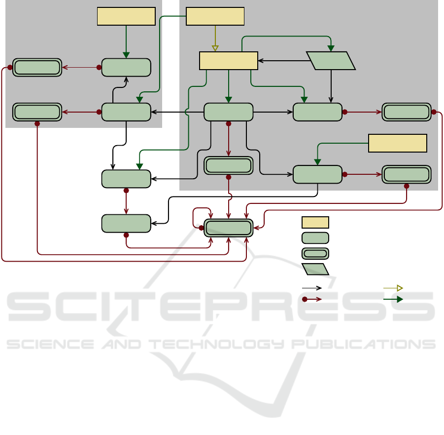
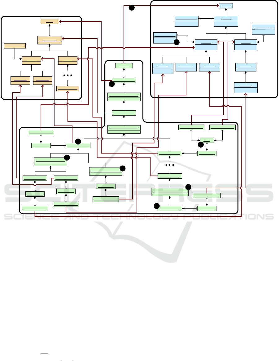
4.2 Exemplary Model System
As example use case, we refer to the graph library
example of Section 3. Figure 5 shows the involved
system of models for a cutout of the domain model
containing the ALF classes Graph (cf. Figure 1) and
Vertex (cf. Figure 3, above) and several child ele-
ments; for the sake of readability, only inter-model
dependencies and no cross references between model
elements are visualized. For each ALF class within
the domain model (AST), one representation model is
present (REPR 1 and REPR 2). Both representation
models have root blocks that refer to the respective
class.
For each object that is represented by the editor,
an object correspondence (within the CORR model)
stores this representation relation together with the re-
spective projection rule (contained in the syntax defi-
nition model CSYN) as well as the product line map-
ping element (in the PL-MAPP model). In this exam-
ple, the correspondence model contains an object cor-
respondence (1) for the root block (2) that represents
MODELSWARD 2021 - 9th International Conference on Model-Driven Engineering and Software Development
300
PL-EDITOR 1 PL-EDITOR 2
REPR 1 REPR 2
CSYN
AST
PL-MAPP
CORR
UI-MAPP 1 UI-MAPP 2
: Block : Annotation
: Cell
: Line
: Cell
: Cell
: Body
: Block : Annotation
: Cell
: Fragment
: Block
: Annotation
: Cell
: BlockPattern : BlockPattern : LinePattern
: Unit
: Package
: Class
: Operation
: Parameter
: Class
: Mapping
: Mapping
: Mapping: Annotation
: Mapping: Annotation
: Mapping : Annotation
: ObjCorr
: AnnotCorr
: ObjCorr
: AnnotCorr
: ObjCorr
: ObjCorr
: AnnotCorr
label = public
label = class
expanded = false
label = GraphLibrary
label = Edges
label = Vertices
expanded = true
expanded = true
name = Class
name = Operation
name = Parameter
name = graphLibrary
name = Graph
name = addEdge
name = source
direction = IN
name = Vertex
1
2
3
4
5
6
7
8
Figure 5: Example system of models for the graph library example (cutout). AST objects which are visible within the editors,
their representation elements, and related elements have a red filling while annotations and their corresponding elements are
marked by a yellow filling. Blue arrows symbolize cross references between components of the system. Elements of the
representation models that exhibit analogous elements within the editors are marked through a blue border. AST objects and
the respective mappings which are not visualized by the editors are grayed out. Diamond arrows stand for direct containment
relations and dashed ones for transitive containment relations between model elements.
the ALF class Graph (3). This element is connected
with the respective projection rule (4) and the product
line mapping element (5). As the editors only show
the representations of the ALF classes, the container
elements (and their product line mappings) do neither
have any representation elements nor any correspon-
dence elements.
In general, the containment hierarchy of the ab-
stract syntax tree is also applied for the correspon-
dence model and the representation models. Thus,
in case of the class Graph that contains the ALF op-
eration addEdge, the representation element for the
operation is contained in the representation element
for the class and the correspondence element for the
operation is contained in the correspondence element
for the class. The product line mapping elements also
possess this structure; more details about the mapping
models are provided by Section 5.
While the referenced features are contained in the
feature model, the annotation expressions are per-
sisted as children of mappings within the product
line mapping model. Besides the representation ele-
ments of the domain model, the representation model
also comprises elements for the annotations (and their
cells). For instance, the annotation Vertices (6) is rep-
resented by a REPR annotation (7) with an annota-
tion correspondence element (8). The representation
model also stores the information that the annotation
for the whole class Graph is hidden.
Each representation model (REPR) is visualized
by a specific editor (EDITOR) where the traces are
persisted by a specific transient data structure (UI-
MAPP). The editor contains corresponding graphical
elements for blocks, bodies, cells, and annotations.
Note that for hidden annotations – for which the at-
tribute expanded is set to false –, their cells are not
part of the editor presentation.
A Framework for Projectional Multi-variant Model Editors
301
5 MAPPING DOMAIN MODEL
AND ANNOTATIONS
After a brief overview of the metamodel for feature
models, this section outlines structure and concepts of
the product line mapping models that persist the anno-
tations of domain model elements. Finally, for an ex-
ample use case, the internal structure of the concrete
feature model and the mapping model is depicted.
5.1 Feature Model
Figure 6 shows the metamodel for feature models.
One feature constitutes the unique root feature. Each
feature has a name and a boolean value whether it is
mandatory. Features may be groups – which can con-
tain arbitrarily many child features – or atomic fea-
tures – that do not have any child features. Further-
more, features may have named attributes for boolean,
integer, real, and string values.
A group is linked to a selection range that indi-
cates how many child features must be selected at
least (minimum number) and may be selected at most
(maximum number). The minimum number must be
less than or equal to the maximum number; further-
more, the minimum number may not be less than the
number of mandatory child features; the maximum
number has to be less than or equal to the number
of child features. For instance, the semantics of OR-
and XOR-groups which are commonly supported by
feature models can be easily expressed by appropriate
selection ranges.
In addition to the feature model tree, cross-tree
constraints, i.e., dependencies between features, can
be specified. To this end, an expression language is
provided that supports common logical operators. By
means of this expression language as well as the con-
cept of selection ranges, arbitrary dependencies be-
tween features can be specified precisely.
Model
Feature
enumeration
AttributeType
Atomic
Group SelectionRange
Attribute
model
0..1
1
root
1
feature
attributes
*
children
*
0..1
parent
range
1
name : EString
mandatory : EBoolean
minimum : EInt
maximum : EInt
name : EString
type : AttributeType
BOOLEAN
INTEGER
REAL
STRING
Figure 6: The metamodel for feature models.
5.2 Mapping Model
This section covers the metamodel for mapping mod-
els, i.e., models connecting domain model elements
and annotations. As stated in Section 4, this model
is conceptually separated from the correspondence
model, i.e., the internal mapping model of the edi-
tor core. The domain engineer is not exposed to the
internal structure of the product line mapping model
directly; rather, annotations are visualized with the
domain model elements by the editor within an in-
tegrated, user-friendly view.
Figure 7 shows the metamodel of the product line
mapping metamodel. The mapping model consists of
Mapping instances referring to the domain model. In
order to provide the different kinds of annotations in-
troduced in Section 3, three kinds of mappings are
distinguished; concrete examples are depicted by Fig-
ure 3.
• All ObjectMapping instances refer to objects
within the domain model, i.e., EObject instances.
Object mappings are annotated if a domain model
object is annotated, e.g., the whole class Vertex.
• All PropertyMapping instances correspond to
structural features (attributes or references), i.e.,
EStructuralFeature instances, in the context of an
object. Annotations contained in property map-
pings refer to annotated options, e.g., the declara-
tion fragment of supertypes of the ALF class Ver-
Expression
UnaryExpression
NotParen
BinaryExpression
And Xor Or
FeatureReference
(from feat)
Feature
AttributeReference
(from feat)
Attribute
Annotation
Mapping
ObjectMapping
(from ecore)
EObject
Model
(from feat)
Model
ValueMapping PropertyMapping
(from ecore)
EStructuralFeature
AttributeOrCrossMapping
ContainmentMapping
rootMappings
0..*
container
1..1
properties
0..*
0..1
containment
children
0..*
1..1
property
values
0..*
annotation
0..1
root
1..1
expression
1..1
1..1
left
1..1
right
mappedObject
1..1
mappedProperty
1..1
1..1
featModel
1..1
feature
1..1
attribute
index : EInt
Figure 7: The metamodel for (product line) mapping mod-
els.
MODELSWARD 2021 - 9th International Conference on Model-Driven Engineering and Software Development
302

tex.
• All ValueMapping instances represent attribute
values or cross links within the domain model.
Value mappings are used for annotations refer-
ring to values, e.g., the natural literal for the initial
weight value in the class Edge.
The structure of the mapping model reflects the con-
tainment hierarchy of the domain model elements.
Direct child mappings of object mappings are always
property mappings – corresponding to their structural
features. Direct child mappings of property mappings
are either object mappings – in case the property map-
ping refers to a containment reference – or value map-
pings – otherwise. Different value mappings con-
tained in the same property mapping – which occurs
in case of multi-valued structural features – can be
identified by their index values. The index value of
a value mapping describes the index of the element
within the respective collection in the domain model;
note that EMF always provides ordered collections
for multi-valued structural features. The root map-
pings, i.e., the mappings referring to domain model
root objects, build a flat collection in the root Model
instance.
As a consequence of this analogous structure,
mapping elements can be located very easily by em-
ploying their location in the domain model. The ed-
itor framework applies the principle of lazy creation
and deletion: When a new annotation is created, only
mapping elements are created which are necessary for
this annotation; these elements comprise the mapping
element that contains the annotation as well as all con-
tainer mappings up to the object mapping for the do-
main model root. Furthermore, when an annotation is
deleted, the mapping elements are not removed; map-
ping elements are deleted if and only if the respective
domain model elements are deleted.
Annotations are stored as subtrees within the re-
spective mapping element. The root Expression in-
stance is directly referenced by the Annotation object.
The child expressions are arbitrarily nested according
to the respective logical operator precedence. Atomic
expressions pose references to features or feature at-
tributes.
5.3 Example Annotation Mapping
Figure 8 depicts the internal structure of the feature
model as well as the mapping model for a cutout
of the multi-variant domain model presented in Fig-
ure 3. Besides other artifacts that are comprised by
the graph product line, the given ALF package con-
tains the classes Vertex and Edge. The ALF class Ver-
tex contains the properties color and label and inherits
from the class Shape. The ALF class Edge provides
the operation addEdge which transitively contains a
natural literal expression. The property weight within
the class Edge as well as other children of the opera-
tion addEdge are not considered here.
The feature model (cf. Figure 2) comprises the
features Position, Colored, Labeled, and Weighted as
atomic features. All other features are groups with
default selection ranges, e.g., the group Vertices has
a selection range (1) with minimum value 1 – since
it has one mandatory child feature – and maximum
value 3 – since it has three child features.
The unique global mapping model is linked (2)
to the unique global feature model. As exactly one
abstract syntax tree – with different views of it – is
present, the mapping model has one root mapping (3)
that references the domain model root. The contain-
ment hierarchy of the abstract syntax tree leads to an
alternating sequence of ObjectMapping and Contain-
mentMapping instances. Since both properties color
and label are contained in the same class Vertex and
refer to the same containment reference, the respec-
tive object mappings are children of the same con-
tainment mapping (4); analogously for the two ALF
classes within one package. The attribute for the nat-
ural literal is represented by an AttributeOrCrossMap-
ping instance (5) with a single ValueMapping object
(6). Due to the lazy creation principle, the mapping
model exhibits no mapping element which neither
contains an annotation nor another mapping (as the
mapping element would be useless).
Annotations are stored as subtrees within the re-
spective mappings. The annotations for the classes
and the properties are internally represented as child
objects of the respective object mappings, e.g., the
annotation Vertices (i.e., a feature reference) within
the mapping (7) for the class Vertex. The annotation
for the superclass of the class Vertex comprises the
whole optional structural feature; thus, the respective
annotation constitutes a child element of the Contain-
mentMapping instance (8) for the generalization ob-
jects. The annotation for the natural literal value is a
child element of the single value mapping (6). Map-
pings that do not directly contain annotations only
serve as members within the structure of the complete
containment hierarchy.
In this use case, the annotations contain both
feature references – referring to groups or atomic
features – and attribute references. The AND-
conjunction within the annotation of the class Edge is
represented by a binary tree (9) with the two operands
as its leaf elements.
A Framework for Projectional Multi-variant Model Editors
303
AST
FEAT
PL-MAPP
: Model
: ObjectMapping
: ContainmentMapping
: ObjectMapping
: ContainmentMapping
: ObjectMapping: Annotation
: FeatureReference
: ContainmentMapping
: ObjectMapping
: Annotation
: FeatureReference
: ObjectMapping
: Annotation
: FeatureReference
: ContainmentMapping
: Annotation
: FeatureReference
: ObjectMapping : Annotation
: And
: FeatureReference : FeatureReference
: ObjectMapping
: AttributeOrCrossMapping
: ValueMapping : Annotation
: AttributeReference
: Atomic : Atomic : Atomic
: Group
: SelectionRange
: Atomic
: Attribute
: Group
: SelectionRange
: Group: SelectionRange
: Model
: Unit
: Package
: Class
: Generalization
: Property : Property
: Class
: NaturalLiteral
rootMappings
container
properties
containment
children
container
properties
containment
children
annotation
root
container
properties
containment
children
annotation
root
children
annotation
root
properties
annotation
root
children
annotation
root
right
left
container
children
container
properties
property
values
annotation
root
model
root
parent
children children
range
parent
children children children
range
parent
children
range
feature
attributes
ownedMember
namespace
ownedMember ownedMember
namespace
ownedMember ownedMember
general
generalization
namespace
mappedProp. = ownedMember
mappedProp. = ownedMember
mappedProp. = ownedMember
mappedProp. = generalization
mappedProp. = image
name = GraphLibrary
mandatory = true
minimum = 2
maximum = 2
name = Vertices
mandatory = true
minimum = 1
maximum = 3
name = Edges
mandatory = true
minimum = 0
maximum = 1
name = Position
mandatory = true
name = Colored name = Labeled
name = Weighted
name = defaultValue
type = INTEGER
name = graphLibrary
name = Vertex
name = Edge
name = color name = label
1
2
3
4
5
6
7
8
9
Figure 8: The internal representation of an example mapping model (PL-MAPP) with cross links to one feature model (FEAT)
and one domain model (AST) that constitutes a cutout of the model in Figure 3. Inter-model cross references are visualized
by red, bold arrows.
6 CONCLUSION
We presented a generic framework for building pro-
jectional multi-variant editors which are based on fea-
ture models for defining variability and support nega-
tive variability by annotating domain model elements
with feature expressions. Human-readable textual no-
tation is employed at the user interface. In particular,
the notation provides for a clear separation between
domain model elements and annotations, and offers a
variety of commands for flexible filtering of variabil-
ity information (Section 3).
Projectional multi-variant editors have not only
been designed for model-driven engineering; they
have also been realized with model-driven engineer-
ing. Thus, projectional multi-variant editors consti-
tute a complex use case for the application of model-
driven engineering. As described in Section 4, we
devised a notation for megamodeling which we ap-
plied to describe the internal architecture of projec-
tional multi-variant editors. Furthermore, Section 5
illustrates the complexity of the models employed in-
ternally by means of the mapping between domain
models and feature models.
The work presented in this paper is still ongo-
ing. Future work will include support for defining
partial or total feature configurations and configuring
multi-variant domain models accordingly. Here, en-
suring well-formedness of configured domain mod-
els constitutes an important challenge which may be
addressed along the lines of our previous work on
FAMILE (Buchmann and Schw
¨
agerl, 2012). Please
note that configuration of feature models and domain
models is essential not only for application engineer-
ing but should be supported in domain engineering,
as well. In domain engineering, configuration sup-
port enables previews of configured domain models
which may be visualized by coloring and eliding. In
MODELSWARD 2021 - 9th International Conference on Model-Driven Engineering and Software Development
304

addition, such previews will be editable. In this way,
the projectional multi-variant editor will support auto-
mated management of annotations in a similar way as
variation control systems (avoiding their view-update
problems since each editing command always refers
to the underlying multi-variant model).
REFERENCES
Apel, S. and K
¨
astner, C. (2009). Virtual separation of con-
cerns - A second chance for preprocessors. J. Object
Technol., 8(6):59–78.
Apel, S., K
¨
astner, C., and Lengauer, C. (2009). Feature-
House: Language-independent, automated software
composition. In Proceedings of the ACM/IEEE Inter-
national Conference on Software Engineering (ICSE),
pages 221–231. IEEE.
Buchmann, T. and Schw
¨
agerl, F. (2012). Ensuring well-
formedness of configured domain models in model-
driven product lines based on negative variability.
In Schaefer, I. and Th
¨
um, T., editors, 4th Interna-
tional Workshop on Feature-Oriented Software Devel-
opment, FOSD ’12, Dresden, Germany - September
24 - 25, 2012, pages 37–44. ACM.
Buchmann, T. and Schw
¨
agerl, F. (2012). FAMILE: tool
support for evolving model-driven product lines. In
St
¨
orrle, H., Botterweck, G., Bourdell
`
es, M., Kolovos,
D., Paige, R., Roubtsova, E., Rubin, J., and Tolvanen,
J.-P., editors, Joint Proceedings of co-located Events
at the 8th European Conference on Modelling Foun-
dations and Applications, CEUR WS, pages 59–62,
Building 321, DK-2800 Kongens Lyngby. Technical
University of Denmark (DTU).
Heidenreich, F., Kopcsek, J., and Wende, C. (2008). Fea-
turemapper: mapping features to models. In Sch
¨
afer,
W., Dwyer, M. B., and Gruhn, V., editors, 30th Inter-
national Conference on Software Engineering (ICSE
2008), Leipzig, Germany, May 10-18, 2008, Compan-
ion Volume, pages 943–944. ACM.
Kang, K. C., Cohen, S. G., Hess, J. A., Novak, W. E.,
and Peterson, A. S. (1990). Feature-oriented domain
analysis (FODA) feasibility study. Technical Report
CMU/SEI-90-TR-21, Software Engineering Institute,
Carnegie Mellon University.
Linsbauer, L., Schw
¨
agerl, F., Berger, T., and Gr
¨
unbacher, P.
(2021). Concepts of variation control systems. Jour-
nal of Systems and Software, 171:25.
Lopez-Herrejon, R. E. and Batory, D. S. (2001). A standard
problem for evaluating product-line methodologies. In
Proc. 3rd International Conference on Generative and
Component-Based Software Engineering, GCSE ’01,
pages 10–24, London, UK. Springer.
Mukelabai, M., Behringer, B., Fey, M., Palz, J., Kr
¨
uger, J.,
and Berger, T. (2018). Multi-view editing of software
product lines with peopl. In Chaudron, M., Crnkovic,
I., Chechik, M., and Harman, M., editors, Proceed-
ings of the 40th International Conference on Software
Engineering: Companion Proceeedings, ICSE 2018,
Gothenburg, Sweden, May 27 - June 03, 2018, pages
81–84. ACM.
OMG (2017). Action Language for Foundational UML
(Alf). Object Management Group, Needham, MA,
formal/2017-07-04 edition.
OMG (2020). Semantics of a Foundational Subset for Ex-
ecutable UML Models (fUML). Object Management
Group, Needham, MA, ptc/2020-05-10 edition.
Pohl, K., B
¨
ockle, G., and van der Linden, F. (2005). Soft-
ware Product Line Engineering - Foundations, Prin-
ciples, and Techniques. Springer.
Schaefer, I. (2018). A personal history of delta mod-
elling. In M
¨
uller, P. and Schaefer, I., editors, Prin-
cipled Software Development - Essays Dedicated to
Arnd Poetzsch-Heffter on the Occasion of his 60th
Birthday, pages 241–250. Springer.
Schobbens, P., Heymans, P., and Trigaux, J. (2006). Fea-
ture diagrams: A survey and a formal semantics. In
14th IEEE International Conference on Requirements
Engineering (RE 2006), 11-15 September 2006, Min-
neapolis/St.Paul, Minnesota, USA, pages 136–145.
Schr
¨
opfer, J., Buchmann, T., and Westfechtel, B. (2020).
A generic projectional editor for EMF models. In
Hammoudi, S., Pires, L. F., and Selic, B., editors,
Proceedings of the 8th International Conference on
Model-Driven Engineering and Software Develop-
ment (MODELSWARD 2020), pages 381–392. IN-
STICC, SciTePress.
Schw
¨
agerl, F., Buchmann, T., and Westfechtel, B. (2015).
SuperMod - A model-driven tool that combines ver-
sion control and software product line engineer-
ing. In Proc. 10th International Conference on Soft-
ware Paradigm Trends, pages 5–18, Colmar, Alsace,
France. SCITEPRESS.
Schw
¨
agerl, F. and Westfechtel, B. (2019). Integrated
revision and variation control for evolving model-
driven software product lines. Softw. Syst. Model.,
18(6):3373–3420.
Steinberg, D., Budinsky, F., Paternostro, M., and Merks,
E. (2009). EMF Eclipse Modeling Framework. The
Eclipse Series. Addison-Wesley, Boston, MA, 2nd
edition.
V
¨
olter, M., Siegmund, J., Berger, T., and Kolb, B. (2014).
Towards user-friendly projectional editors. In Soft-
ware Language Engineering - 7th International Con-
ference, SLE 2014, V
¨
aster
˚
as, Sweden, September 15-
16, 2014. Proceedings, pages 41–61.
V
¨
olter, M., Stahl, T., Bettin, J., Haase, A., and Helsen, S.
(2006). Model-Driven Software Development: Tech-
nology, Engineering, Management. John Wiley &
Sons.
A Framework for Projectional Multi-variant Model Editors
305
