Continuous Integration in Multi-view Modeling:
A Model Transformation Pipeline Architecture for
Production Systems Engineering
Felix Rinker
1,2 a
, Laura Waltersdorfer
1 b
, Kristof Meixner
1,2 c
,
Dietmar Winkler
1,2 d
, Arndt L
¨
uder
3 e
and Stefan Biffl
1 f
1
Institute of Information Systems Engineering, TU Wien, Vienna, Austria
2
CDL for Security & Quality Improvement in the Production System Lifecycle, TU Wien, Vienna, Austria
3
Institute of Ergonomics, Manufacturing Systems and Automation OVGU, Magdeburg, Germany
Keywords:
Domain-specific Modeling, Production Systems Engineering, Model-driven Engineering, Domain-specific
Languages, Model Transformation, Multi-disciplinary Engineering.
Abstract:
Background. Systems modeling in Production Systems Engineering (PSE) is complex: Multiple views from
different disciplines have to be integrated, while semantic differences stemming from various descriptions
must be bridged. Aim. This paper proposes the Multi-view Modeling Framework (MvMF) approach and ar-
chitecture of a model transformation pipeline. The approach aims to ease setup and shorten configuration effort
of multi-view modeling operations and support the reusability of modeling environments, like additional view
integration. Method. We combine multi-view modeling with principles from distributed, agile workflows, i.e.,
Git and Continuous Integration. Results. The MvMF provides a light-weight modeling operation environment
for AutomationML (AML) models. We show MvMF capabilities and demonstrate the feasibility of MvMF
with a demonstrating use case including fundamental model operation features, such as compare and merge.
Conclusion. Increasing requirements on the traceability of changes and validation of system designs require
improved and extended model transformations and integration mechanisms. The proposed architecture and
prototype design represents a first step towards an agile PSE modeling workflow.
1 INTRODUCTION
Data integration in the industrial domain is a complex
process involving different views and representation
formats coming from distinct engineering domains’
perspectives and tools (Grangel-Gonz
´
alez, 2016).
Various parameters can have an impact on the overall
project environment, a specific project setup, and the
model lifecycle: For instance, engineering tool suites
are tailored to single engineering domain require-
ments and hence fulfill use-case specific purposes
for individual domain such as electrical or me-
chanical engineering (Sabou et al., 2017). Examples
a
https://orcid.org/0000-0002-6409-8639
b
https://orcid.org/0000-0002-6932-5036
c
https://orcid.org/0000-0001-7286-1393
d
https://orcid.org/0000-0002-4743-3124
e
https://orcid.org/0000-0001-6537-9742
f
https://orcid.org/0000-0002-3413-7780
include specific tools, such as AutoCAD
1
for
CAD drawing, discipline-specific tools, like EPLAN
2
for the electrical domain, and a plethora of other
modeling formats and tools (Strahilov and H
¨
ammerle,
2017). Furthermore, the clients’ requirements can
predetermine the selection of tools: Depending on
the clients’ system landscape, certain frameworks,
tool suites, modeling languages, or technologies need
to be applied. These factors can lead to modeling
inconsistencies and synchronization errors in the
basic model transformation process. The three main
operations to transform models into different views
are (a) import of an artifact, (b) one or more model
operations, and (c) export of an artifact.
Unfortunately, these steps are currently conducted
manually by domain experts or executed through
scripts to transform (input) data/artifacts into the
required (output) data/artifacts in different formats.
1
AutoCAD: https://www.autodesk.com/autocad
2
EPLAN: https://www.eplan.de
286
Rinker, F., Waltersdorfer, L., Meixner, K., Winkler, D., Lüder, A. and Biffl, S.
Continuous Integration in Multi-view Modeling: A Model Transformation Pipeline Architecture for Production Systems Engineering.
DOI: 10.5220/0010309902860293
In Proceedings of the 9th International Conference on Model-Driven Engineering and Software Development (MODELSWARD 2021), pages 286-293
ISBN: 978-989-758-487-9
Copyright
c
2021 by SCITEPRESS – Science and Technology Publications, Lda. All rights reserved
However, these scripts could break easily if essential
parts are changed, such as model changes. Therefore,
this approach is potentially error-prone and inflexible,
possibly introducing faulty designs or inconsistencies
(Waltersdorfer et al., 2020).
Domain experts, who typically design production
systems, need tool and framework support to setup
flexible model transformation structures. Further-
more, the reuse of existing transformers and gener-
ators should require no or limited effort for adapting
them to new project environments. Even if new or
changed requirements, semantic mappings or concept
liftings have to be identified, existing models have
to be extended with new parameters and/or concepts
with limited effort (Dotoli et al., 2019).
Commercial solutions offer central integration
platforms and provide automatic transformation capa-
bilities. Unfortunately, such systems often introduce a
high level of complexity, requiring training and exten-
sive setup time. Furthermore, such systems are often
limited in terms of flexibility (Scheeren and Pereira,
2014).
To tackle these shortcomings, we raise the follow-
ing Research Questions (RQs):
RQ1. What are the main requirements for a flex-
ible model transformation workflow in multi-
disciplinary production systems engineering?
RQ2. Which workflow processes can facilitate
a multi-view model transformation in multi-
disciplinary production systems engineering?
RQ3. Which software system architecture can facili-
tate the flexible model transformation workflow?
Main Contributions of This Paper. (1) A set of re-
quirements derived from an industrial project for a
flexible modeling transformation pipeline. (2) A pro-
cess to define flexible model transformation pipelines
for general purposes, based on agile workflows to
support distributed modeling. (3) An architectural
system design for such a modeling transformation
pipeline. (4) Our approach’s feasibility by providing a
demonstrative use case and implementation based on
AutomationML (AML) and automated with a Contin-
uous Integration (CI) system.
Remainder of this Paper. Section 2 summarizes re-
lated work. Section 3 describes an illustrative use
case, the traditional model transformation process,
and derived requirements. In Section 4, we de-
scribe an improved model transformation workflow
based on continuous integration and model engineer-
ing. In Section 5, we present our solution approach
and the developed Multi-view Modeling Framework
(MvMF). In Section 6, we demonstrate the feasibil-
ity of our approach with the illustrative use case. In
Section 7 we discuss our results and summarize our
findings, limitations and future research.
2 RELATED WORK
This section summarizes current work from integrated
system modeling for Industry 4.0, model-based De-
velopment and IT Operations (DevOps), and model-
ing interoperability practices.
2.1 Integrated System Modeling for
Industry 4.0
System modeling in Production Systems Engineer-
ing (PSE) is a complex task due to the co-existence
of diverse views and the variety of tools, languages,
and technologies (Strahilov and H
¨
ammerle, 2017). In
PSE, domain-specific modeling languages are crucial
for facilitating model-based engineering and imple-
menting the Industry 4.0 vision for complex data-
driven use cases (Wortmann et al., 2020).
Several initiatives developed industry standards,
increasingly used to model and specify domain-
specific contexts. Examples are the Systems Model-
ing Language (SysML)
3
and AutomationML (AML)
4
for engineering data exchange, Business Process
Model and Notation (BPMN)
5
for generic process de-
scriptions, or Simulink
6
for control and signal pro-
cessing. Yet, data exchange in industrial settings is
still centered around document-based exchange (Pon-
sard et al., 2020) and high heterogeneity of formats,
hindering seamless model integration and transforma-
tion. Multi-level integration is necessary to reap the
benefits of digitization in the manufacturing domain.
Well-established general-purpose frameworks and
concepts proposed by the Multi-Disciplinary Engi-
neering (MDE) community are ATLAS Transforma-
tion Language (ATL)
7
in conformance with the Meta
Object Facility (MOF)
8
for model transformations
(Jouault et al., 2008). EMF Compare (Toulm
´
e, 2006)
is a framework for model comparison, conflict detec-
tion and merging.
A major concern for both modeling and PSE com-
munity is the need for adequate multi-view model-
ing processes (Atkinson et al., 2019; Feldmann et al.,
2019), which is often not supported. However, var-
3
SysML: https://www.sysml.org
4
AutomationML: https://www.automationml.org
5
BPMN: https://www.bpmn.org
6
Simulink: https://www.mathworks.com/simulink
7
ATL: https://www.eclipse.org/atl
8
MOF: https://www.omg.org/mof
Continuous Integration in Multi-view Modeling: A Model Transformation Pipeline Architecture for Production Systems Engineering
287
ious approaches exist in multi-view modeling and
there is need for more empirical evaluation in this
field (Atkinson et al., 2014). (Tunjic and Atkinson,
2015) further define the notion of a Single Underly-
ing Model (SUM), as a common unified model, which
could be automatically populated based on the infor-
mation from the single views based on previously de-
fined mappings. We will demonstrate the concept of
SUM to our use case described in Section 3 and en-
able such a common model with the process of dis-
tributed tool support and transformation pipeline as
described in Section 4.
2.2 Model-based DevOps
DevOps, stemming from software (Dev)elopment and
IT (Op)erations, is a process improvement approach
aiming to shorten the development life cycle and pro-
moting continuous delivery while achieving high soft-
ware quality (Ebert et al., 2016). The main steps in-
clude code integration, deployment and delivery, en-
abling agile working methods. Example methods and
technologies include code reviews, version manage-
ment, build frameworks, static and dynamic tests.
However, typical best-practices focus on source
code, leaving out other artifacts such as non-textual
artifacts, i.e., models. (Garcia and Cabot, 2018) ex-
tend the concept of continuous integration and de-
scribe the combination of continuous delivery prac-
tices and model-driven engineering techniques. Gar-
cia and Cabot provide proof of concept by showing
an integrated modeling process on a Create / Read /
Update / Delete (CRUD)-based web application with
continuous development tool and method support,
such as Jenkins
9
and test automation. (Wortmann
et al., 2020) propose the model-based DevOps ap-
proach to support the Industry 4.0 vision by utilizing
findings from both fields (namely, MDE and software
engineering) and combining them in new ways.
3 ENGINEERING USE CASE &
PROCESS
This section describes the coil car use case from the
industrial domain steel mill engineering and the cur-
rent manual model transformation process.
Coil Car Use Case. In the steel industry, rolling is a
crucial production step where steel is passed through
consecutive pairs of rolls to form the steel, reducing
and evening its thickness. The results are long, thin
9
Jenkins: https://www.jenkins-ci.org
steel sheets reeled onto large coils during the rolling
process and transported by coil cars. Naturally, these
coil cars require precise design and manufacturing to
handle the weight of the steel coils and the forces ap-
plied, e.g., by accelerating the coils’ mass. Hence, a
crucial part of such a coil car is the motor, which, in
practice, is often a so-called Squirrel Cage Motor.
Engineering a squirrel cage motor for a coil car
requires at least three different views, i.e., mechanic,
electric and programming, with respective engineer-
ing artifacts and models (Biffl et al., 2019). Due
to the growing complexity of designs and dependen-
cies, real-time simulations of production systems are
needed which require a distinct simulation view. To
enable such simulations This model view can then
be exported into a standardized data format, such as
AML and used to generate an automated factory sim-
ulation with Unity
10
and Simulink.
Manual Model Transformation Process. In the
basic model transformation process, multiple design
views on a production system, e.g. different disci-
plines, need to be mapped to each other for a holis-
tic understanding of the entire system and enrich the
other views regarding connections and dependencies.
As an illustrative example, in PSE, the mechanic
view describes hardware components, like the coil car
and its parts, e.g. the squirrel cage motor. The electri-
cal view describes the electrical components, like ca-
bles, necessary inputs, and the wiring layout, which
depend on the mechanical parts but also influence
them. This data is stored in oftentimes proprietary
different engineering artifacts. Engineers need to ex-
change information and engineering data frequently,
since the system design is not finalized in a single pro-
cess run but rather evolves over multiple cycles. Con-
sistency and change tracking is of high importance.
In case of a missing common view on the model
concepts, distinct views have to be mapped to each
other. This is done bidirectionally in point-to-point
mappings, which is cumbersome. Furthermore, with
a growing number of views, the required n-to-n trans-
formations between models rises drastically.
Currently, for most cases, domain experts have
to execute these workflows manually, often by ex-
porting spreadsheet data or proprietary formats from
discipline-specific tools, to edit the data manually and
then export it for data consumers from other disci-
plines. The manual nature of the process can lead to
inconsistencies between local, discipline-specific de-
signs and changes in other disciplines. This might af-
fect the overall design and lead to inconsistencies or
higher commissioning costs.
10
Unity: https://www.unity.com
MODELSWARD 2021 - 9th International Conference on Model-Driven Engineering and Software Development
288
Local View
Tool A
Unified
Model
Compare
Diff Model A
Unified
Model ’
View
Model B
Compare Diff Model B
Merge
Unified
Model ’’
Tool B
Tool A
Dependency
Workflow
View Model Projection
View
Model A
Local View
Common View
Merge
View
Model A’
1
2
3
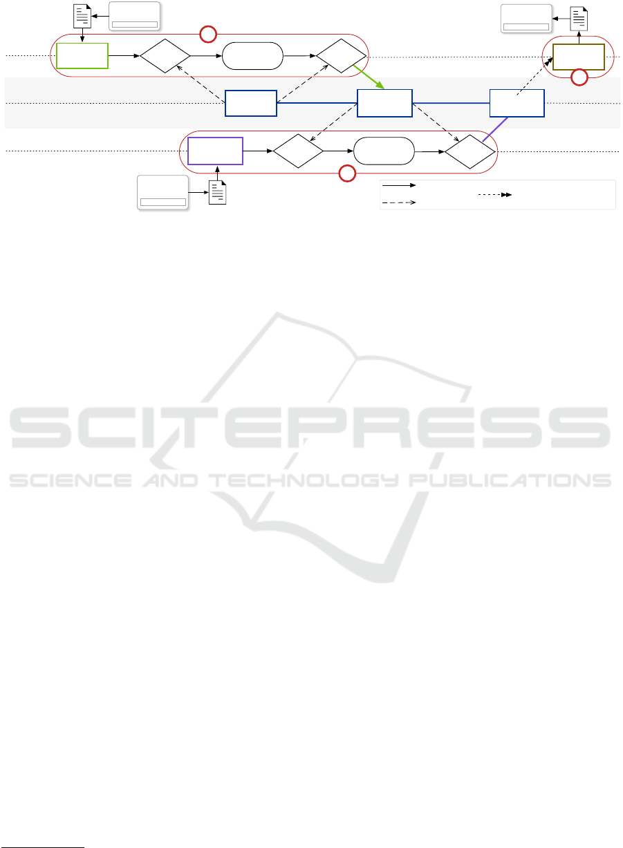
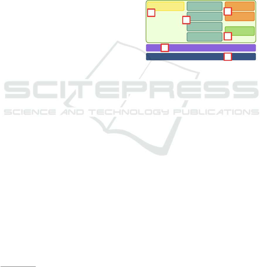
Figure 1: Model transformation workflow for combining tool artifacts in a SUM based on (Tunjic and Atkinson, 2015) and
the Git workflow. (1) Integration of View Model A (2) Integration of View Model B and (3) export of modified View Model A.
Research question 1 focuses on requirements for
a flexible model transformation workflow in multi-
disciplinary production systems engineering. Based
on this use case from an industrial project we derive
the following functional requirements (FR):
FR1.1 Multi-view modeling capabilities. Multi-
ple views have to be supported, to be able to accom-
modate the multi-disciplinary nature of the PSE pro-
cess. Local concepts can be defined that are part of the
discipline-specific designs, which then ca be mapped
into a common concept.
FR1.2 Distributed process synchronization. Dif-
ferent disciplines work in parallel on the designs and
have to synchronize the designs to gain updated in-
formation and check for inconsistencies or changed
dependencies.
FR1.3 Model transformation operations. The fol-
lowing model operations have to be possible: trans-
forming models into a common format, extracting
view-specific model into a unified view and export-
ing models from such a unified view into the local
structure again.
4 IMPROVED MODEL
TRANSFORMATION PROCESS
In this section, we propose an improved multi-view
model transformation workflow compared to the tra-
ditional manual process (cf. Section 3). We combine
multi-view modeling from MDE and continuous in-
tegration with techniques for distributed integration
workflows, such as asynchronous workflow Git
11
.
Use cases that require synchronization of mul-
tiple disciplines and collaborative workflows, more
complex model transformations are needed to support
11
Git: https://www.git-scm.com
multi-disciplinary engineering. Inspired from the ag-
ile development movement, Git supports distributed,
non-linear workflow initially developed for software
engineering. Git works well on tracking changes for
text-based artifacts on a structural level, but lacks
analysis capabilities on a semantic level, which is
needed for model tracking (cf. (Toulm
´
e, 2006)).
Before the engineers can conduct an improved
model transformation workflow, it requires the defi-
nition of a unified model (cf. Figure 1) for all relevant
views. The definition of such a unified model requires
two steps: (a) a pre-defined transformation template
(local view) for each discipline-specific tool corre-
sponding to the discipline-specific structure within
the unified view; and (b) the SUM as conceptually
proposed in (Tunjic and Atkinson, 2015) describing
the semantic links between the local views. This uni-
fied view model acts as a SUM, explaining how dif-
ferent views and overlapping model components are
mapped into a common view. The improved model
transformation workflow is depicted in Figure 1 and
consists of three steps:
Step 1 Integration of View Model A. Engineer A
enters the model transformation workflow with edit-
ing an artifact in Tool A (see upper left side in Fig-
ure 1). The engineer wants to integrate the model-
ing information into the unified model (central lane
in Figure 1). First, the artifact is exported from the
discipline-specific Tool A into, e.g., a Comma Sep-
arated Value (CSV) file. Then, a transformer trans-
forms the tool-specific format from Tool A into View
Model A the previously defined discipline-specific
template. This populated template is then compared
to the SUM to detect differences between the two ver-
sions based on the changes. Changes can include new
elements, and the modification and deletion of ele-
ments. The result of this step is a list of changes,
which can be reviewed by Engineer A. The core ad-
Continuous Integration in Multi-view Modeling: A Model Transformation Pipeline Architecture for Production Systems Engineering
289
vantage of this task is that the engineer can specify
which changes to accept or decline. Based on this
list, the changes are merged into the unified model,
creating a new version. The changes are available for
all stakeholders of the workflow when accessing the
new unified model version.
Step 2 Integration of View Model B. Again, the
tool-specific data of Tool B has to be transformed into
the discipline-specific View Model B using the corre-
sponding template. Then, the transformed structure
is compared to the new unified model version. The
difference to Step 1 is that this unified model version
has the changes of View Model A incorporated. Simi-
lar to Step 1, the changes are calculated and can then
be viewed as a list. Engineer B can again select or re-
ject changes and merge the model data to the unified
model version creating an updated model.
Step 3 Extraction of Modified View Model A.
Based on the unified model version, created in Step 2.
Engineer A can now extract the most recent unified
model version, which consists of Engineer A and En-
gineer B’s local changes. The local view of View
Model A can be generated from this updated unified
model version, so Engineer A can also access the data
according to discipline-specific tool A.
5 MULTI-VIEW MODEL
TRANSFORMATION
FRAMEWORK AND PIPELINE
This section describes the solution approach and
architecture for a Multi-view Modeling Frame-
work (MvMF) for production systems engineering.
The MvMF is inspired by the Eclipse Modeling
Framework (EMF), a well-established meta-modeling
framework with advanced capabilities and tool sup-
port and provides features like comparing and merg-
ing features and views (Bruneliere et al., 2015) for
the integration of heterogeneous models. However,
the framework is heavily coupled with the Eclipse
12
environment, which introduces a high level of com-
plexity and setup effort (Batory and Altoyan, 2020).
From the requirements elicitation (cf. Section 3)
and previous works we infer that accessibility and un-
derstandability for non-modeling experts is a major
concern for engineers in PSE. The EMF tools have
been developed for users with model-driven software
engineering expertise and knowledge, which cannot
be expected from domain experts from other disci-
plines. Novel approaches, like low code in indus-
try for general (Sanchis et al., 2020) and specifi-
12
Eclipse: https://www.eclipse.org
cally in model engineering (Tisi et al., 2019), try to
minimize setup and training efforts for domain ex-
perts not familiar with software engineering or model
engineering techniques. We chose a light-weight,
Service-Oriented Architecture (SOA) that fulfills our
use case’s requirements to employ the advantages of
model engineering while maintaining a low complex-
ity level on the modeling and configuration level. The
description of the SUM corresponds to the MOF hi-
erarchy Layer 3, i.e., the meta-metamodel. More-
over, the orchestration of model operation services
improves the adaptability of the workflow and ease
the setup and configuration effort of our approach.
Comparator
Merger
Converter
XML
CSV
RuleEngine
MvMF
Project Gen
UnitTests
MvMF Service CLIs
MTP / CI Server
1
2
3
4
5
6
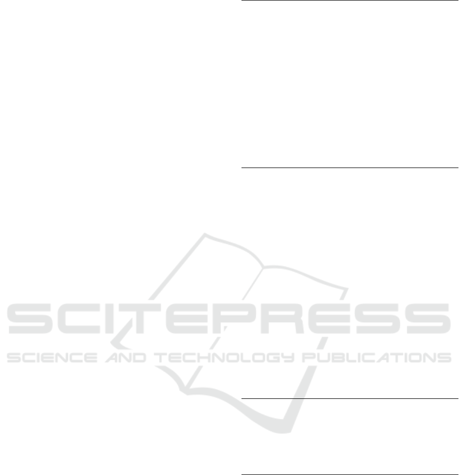
Figure 2: Architectural system design of the Model Trans-
formation Pipeline System and its components.
The architectural system design of the developed
Model Transformation Pipeline System is depicted in
Figure 2. The MvMF compromises four components:
(1) Model Generator. The ProjectGenerator is
used to build the SUM template and the respective
discipline-specific views required to setup the MvMF
for a particular project.
(2) Model Integration consists of four model opera-
tion services: The Converter converts a view-specific
model into a SUM comparable-structure. The ser-
vice can also extract a view-specific model from the
SUM. The Comparator compares two models of the
same structure and calculates the differences. The
Merger consolidates the changes from the previous
step into the SUM. The RuleEngine is used to prop-
agate changes into different views based on defined
rules.
(3) Transformer. The CSVTransformer and XML-
Transformer are needed for the Text-to-Model trans-
formation to import and export the tool-specific arti-
facts.
(4) Model Testing. The UnitTests are small indepen-
dent tests used to assess consistency and quality con-
cerns, e.g., of the model data.
The (5) MvMF Model Service Command Line
Interfaces (CLIs) provides the means to access the
MvMF services through specific CLIs. This allows
the individual utilization of each service on the com-
MODELSWARD 2021 - 9th International Conference on Model-Driven Engineering and Software Development
290
mand line by specifying the needed input and output
parameters, e.g., for combing them in bash scripts.
Beyond that, an advantage is the flexible combination
of MvMF services that can be used in a pipeline con-
figuration and executed through automation services.
The (6) Model Transformation Pipeline compo-
nent provides Pipeline Configuration files to orches-
trate the pipelines. These configuration files define
the automation of the model transformation opera-
tions. If additional model operations are required,
such as generating a report for a manager, further
model transformation pipelines can be configured.
6 FEASIBILITY STUDY
This section discusses the MvMF’s feasibility with a
model transformation pipeline of the improved work-
flow and system design.
6.1 Multi-view Modeling Framework
The use case described in Section 3, poses multiple
challenges to the model transformation process. En-
gineers need to design their system models in paral-
lel while anticipating and incorporating changes from
other disciplines and maintaining a updated system
overview. Model integration with multiple views can
lead to merge conflicts, leading to errors or data loss if
not handled correctly. The number of views can eas-
ily increase the complexity of the underlying model
operations, requiring advanced tooling.
Hence, before starting with the model transforma-
tion workflow, domain experts from the correspond-
ing disciplines initially need to design and agree upon
a SUM, the meta-metamodel (Rinker et al., 2019).
This model contains all relevant views, concepts, at-
tributes and reference links integrating concepts of
the heterogeneous artifacts. A simplified example of
such project configuration described in Yet Another
Markup Language (YAML), based on an initial con-
ceptual design (L
¨
uder et al., 2019) (cf. Listing 1).
In the listing, an example concept SquirrelCage-
Motor is specified and the concept mappings accord-
ing to the model views (function, mechanic, electric)
are defined. For each view, further tool-specific at-
tributes are provided. The implementation is based on
AML, an industrial engineering data exchange stan-
dard, representing Layer 2 of the MOF. After the ne-
gotiation of the SUM, the workflow of the project
can be configured using the different services of the
framework.
The AML Transformer is a transformer imple-
mentation for the used modeling language AML and
projectDefinition:
projectName: Coilcar
projectID: 8b00555a238b2f
viewDefinitions:
- view: Function
- view: Mechanic
...
conceptMappings:
...
- concept: SquirrelCageMotor
views:
- view: Function
derivedFrom: AMLRCL/ResourceStructure
attributes:
- attribute: FunctionViewID
dataType: xs:string
isIdentifier: true
- attribute: Description
dataType: xs:string
...
- view: Mechanic
...
Listing 1: Demonstrating Project Definition.
needs to be set up by a configuration file. For the
import operation (Text-to-Model), the data artifact is
generally coming from discipline-specific tools based
on the local workflows of domain experts. These data
artifacts need to be mapped to the corresponding view
model. The mappings between the view model and
data artifacts are described in the configuration file,
which needs to be specified by the domain expert be-
fore starting the pipeline workflow.
For the export operation (Model-to-Text), the spe-
cific generated view model out of the unified model
represents the source model that needs to be mapped
to the data structure of a machine-readable data
format (i.e., CSV or Extensible Markup Language
(XML)-based formats). A simplified example of a
transformer configuration is shown in Listing 2.
rootId: 8821238b2
uriScheme: xml
objectMapping:
...
- expression: FUNC_ENGINE
systemUnitClassPath: ARCL/SquirrelCageMotor
listType: FunctionViewToolExport
condition:
- FUNC_CODE="MSC"
...
Listing 2: Demonstrating Transformer Configuration.
The Model-to-Model transformation is conducted
by the CAEX Converter, which is able to convert view
models into the SUM structure to enable model com-
parison capabilities. The conversion can also be ex-
ecuted from the SUM structure back into a specific
view model. In this case, the view-specific data is ex-
tracted from the SUM.
The implemented model comparison (CAEX
Comparer) is based on the internal hierarchical struc-
ture of AML files, i.e, Computer-Aided Engineering
eXchange (CAEX) structure. Our CAEX Comparer,
Continuous Integration in Multi-view Modeling: A Model Transformation Pipeline Architecture for Production Systems Engineering
291
similar to EMF Compare, computes the comparison
and diff analysis of the model based on element at-
tribute level rather than textual level. The service
compares the converted view model in the SUM struc-
ture to the currently instantiated SUM and generates
a list of model differences, i.e., deltas. This list can be
reviewed to either accept or reject single changes. The
reviewed list of changes is merged (CAEX Merger)
into the SUM to generate an updated version. Af-
ter the merge, changes are propagated based on de-
fined rules (CAEX Rule Engine). This can happen if
model elements or attributes depend on semantic links
to the updated view. Subsequently, model validation
is achieved through unit tests on different stages. Au-
tomating the improved model transformation work-
flow, requires a flexible method to link the transfor-
mations to a pipeline sequence.
6.2 Model Transformation Pipeline
In our prototypical implementation we chose Jenkins
as an automation/Continuous Integration (CI) server
to combine the engineering with DevOps and execute
the model transformation workflow.
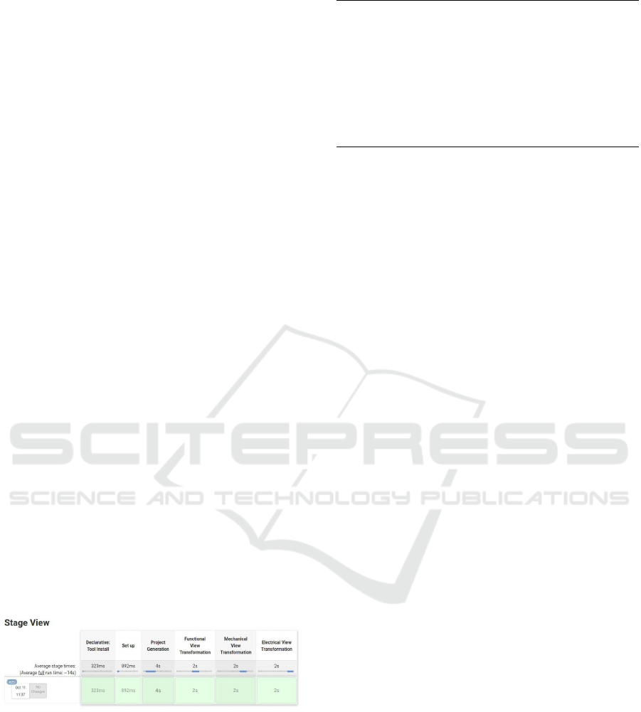
Figure 3 shows the stages of the pipeline, consist-
ing of a tool installation and general set up of the
pipeline environment. After this step, the project’s
model transformers are initially generated, and three
view transformations for the different disciplines are
executed. Listing 3 shows a section of the configu-
ration in Jenkins pipeline syntax with different steps.
First, the required modeling operation services (pro-
vided as jar-files) are defined in the tools section. In
consecutive stages, the model transformations for the
different views are executed with their specific con-
figuration. Engineers can easily modify the pipeline
steps in the CI server and review the implications.
Figure 3: Jenkins Build Pipeline with 6 steps.
Jenkins executes the model transformations pro-
viding feedback on every step’s success (or failure)
and writes the resulting models to the respective lo-
cations. The feedback can further be visualized in an
issue tracker or reporting system.
pipeline {
tools {
jdk 'openjdk11'
}
stage('Project Generation') {
steps {
configFileProvider([configFile(fileId: '115b', targetLocation:
'${GEN_IN}/aml-gen-config.yml')]) {}→
sh 'java -jar aml-class-gen.jar -c ${GEN_IN}/aml-gen-config.yml
-t ${GEN_IN}/usedLibs.aml -o ${GEN_OUT}'→
}
}
stage('Next stage') { steps { ... } }
}
Listing 3: Jenkins Pipeline Configuration.
7 CONCLUSION AND FUTURE
WORK
Advanced engineering use cases, like virtual commis-
sioning or retrofitting, require multi-view modeling to
bridge the gap between the discipline-specific models
and knowledge. This paper identifies requirements
for the implementation of DevOps-enabled multi-
view modeling for Production Systems Engineering
(PSE). The paper presents an agile model transfor-
mation process, the Multi-view Modeling Framework
(MvMF), as a guiding framework for PSE based
on a Single Underlying Model (SUM) and multiple
discipline-specific view models. The main advantage
of the approach is the possibility to define discipline-
specific model transformations and integrate multiple
view models to a SUM while updating correspond-
ing views. We show the feasibility of the agile model
transformation process with a use case from indus-
try using a Continuous Integration (CI) server for au-
tomation.
Limitations. The current implementation aims at
models described in the industry standard Automa-
tionML (AML). This limits our approach’s applica-
bility and we plan to propose extensions. The im-
plementation of MvMF requires additional setup time
and effort a priori. However, the integration effort is
then managed through the pipeline and will, once set
up, save time and complexity. Furthermore, we need
further validation with user studies to demonstrate the
effectiveness of our approach.
Future Work. In the future, we want to couple the
proposed pipeline with a graphical model reviewing
capability for domain experts to check for the com-
pleteness and correctness of model transformations.
Furthermore, we want to extend the capabilities of
our pipeline to enable auditability of data traces and
visual programming to support domain engineers in
setting up the automated workflow.
MODELSWARD 2021 - 9th International Conference on Model-Driven Engineering and Software Development
292

ACKNOWLEDGEMENT
The financial support by the Christian Doppler Re-
search Association, the Austrian Federal Ministry for
Digital & Economic Affairs and the National Foun-
dation for Research, Technology and Development is
gratefully acknowledged.
REFERENCES
Atkinson, C., Burger, E., Meier, J., Reussner, R., and
Winter, A. (2019). Preface to the 1st workshop on
view-oriented software engineering (vose). In 2019
ACM/IEEE 22nd International Conference on Model
Driven Engineering Languages and Systems Compan-
ion (MODELS-C), pages 370–370. IEEE.
Atkinson, C., Gerbig, R., and K
¨
uhne, T. (2014). Comparing
multi-level modeling approaches. In MULTI@ MoD-
ELS, pages 53–61.
Batory, D. S. and Altoyan, N. (2020). Aocl : A Pure-Java
Constraint and Transformation Language for MDE.
In Proceedings of the 8th International Conference
on Model-Driven Engineering and Software Develop-
ment - Volume 1: MODELSWARD,, pages 319–327.
SCITEPRESS.
Biffl, S., L
¨
uder, A., Rinker, F., and Waltersdorfer, L.
(2019). Efficient engineering data exchange in multi-
disciplinary systems engineering. In International
Conference on Advanced Information Systems Engi-
neering, pages 17–31. Springer.
Bruneliere, H., Perez, J. G., Wimmer, M., and Cabot, J.
(2015). Emf views: A view mechanism for integrating
heterogeneous models. In International Conference
on Conceptual Modeling, pages 317–325. Springer.
Dotoli, M., Fay, A., Mi
´
skowicz, M., and Seatzu, C. (2019).
An overview of current technologies and emerging
trends in factory automation. International Journal
of Production Research, 57(15-16):5047–5067.
Ebert, C., Gallardo, G., Hernantes, J., and Serrano, N.
(2016). Devops. Ieee Software, 33(3):94–100.
Feldmann, S., Kernschmidt, K., Wimmer, M., and Vogel-
Heuser, B. (2019). Managing inter-model inconsis-
tencies in model-based systems engineering: Appli-
cation in automated production systems engineering.
Journal of Systems and Software, 153:105–134.
Garcia, J. and Cabot, J. (2018). Stepwise adoption of con-
tinuous delivery in model-driven engineering. In In-
ternational Workshop on Software Engineering As-
pects of Continuous Development and New Paradigms
of Software Production and Deployment, pages 19–
32. Springer.
Grangel-Gonz
´
alez, I. (2016). Semantic data integration for
industry 4.0 standards. In European Knowledge Ac-
quisition Workshop, pages 230–237. Springer.
Jouault, F., Allilaire, F., B
´
ezivin, J., and Kurtev, I. (2008).
ATL: A model transformation tool. Science of com-
puter programming, 72(1-2):31–39.
L
¨
uder, A., Kirchheim, K., Pauly, J., Biffl, S., Rinker, F., and
Waltersdorfer, L. (2019). Supporting the data model
integrator in an engineering network by automating
data integration. In 2019 IEEE 17th International
Conference on Industrial Informatics (INDIN), vol-
ume 1, pages 1229–1234.
Ponsard, C., Darquennes, D., Ramon, V., and Deprez, J.-C.
(2020). Assessment of EMF Model to Text Generation
Strategies and Libraries in an Industrial Context. In
MODELSWARD, pages 433–440.
Rinker, F., Waltersdorfer, L., Meixner, K., and Biffl, S.
(2019). Towards support of global views on common
concepts employing local views. In 24th IEEE Inter-
national Conference on Emerging Technologies and
Factory Automation, ETFA 2019, Zaragoza, Spain,
September 10-13, 2019, pages 1686–1689. IEEE.
Sabou, M., Ekaputra, F. J., and Biffl, S. (2017). Seman-
tic web technologies for data integration in multi-
disciplinary engineering. In Multi-Disciplinary En-
gineering for Cyber-Physical Production Systems,
pages 301–329. Springer.
Sanchis, R., Garc
´
ıa-Perales,
´
O., Fraile, F., and Poler, R.
(2020). Low-code as enabler of digital transforma-
tion in manufacturing industry. Applied Sciences,
10(1):12.
Scheeren, I. and Pereira, C. E. (2014). Combining
model-based systems engineering, simulation and
domain engineering in the development of indus-
trial automation systems: Industrial case study.
In 2014 IEEE 17th International Symposium on
Object/Component/Service-Oriented Real-Time Dis-
tributed Computing, pages 40–47. IEEE.
Strahilov, A. and H
¨
ammerle, H. (2017). Engineering work-
flow and software tool chains of automated produc-
tion systems. In Multi-Disciplinary Engineering for
Cyber-Physical Production Systems, pages 207–234.
Springer.
Tisi, M., Mottu, J., Kolovos, D. S., de Lara, J., Guerra,
E., Ruscio, D. D., Pierantonio, A., and Wimmer, M.
(2019). Lowcomote: Training the next generation of
experts in scalable low-code engineering platforms.
volume 2405 of CEUR Workshop Proceedings, pages
73–78. CEUR-WS.org.
Toulm
´
e, A. (2006). Presentation of EMF Compare Utility.
In Eclipse Modeling Symposium, pages 1–8.
Tunjic, C. and Atkinson, C. (2015). Synchronization of pro-
jective views on a single-underlying-model. In Pro-
ceedings of the 2015 Joint MORSE/VAO Workshop on
Model-Driven Robot Software Engineering and View-
based Software-Engineering, pages 55–58.
Waltersdorfer, L., Rinker, F., Kathrein, L., and Biffl, S.
(2020). Experiences with technical debt and manage-
ment strategies in production systems engineering. In
Proceedings of the 3rd International Conference on
Technical Debt, pages 41–50.
Wortmann, A., Barais, O., Combemale, B., and Wimmer,
M. (2020). Modeling languages in Industry 4.0: an ex-
tended systematic mapping study. Software and Sys-
tems Modeling, 19(1):67–94.
Continuous Integration in Multi-view Modeling: A Model Transformation Pipeline Architecture for Production Systems Engineering
293
