
A Novel Approach for Experimental Earthquake Engineering
Utilizing Mirror Reflections of Point Clouds Collected by Laser
Scanner
Shakhzod Takhirov
1a
, Mukhady Israilov
2
and Sultan Kudratov
3b
1
Department of Civil and Environmental Engineering, University of California, Berkeley, U.S.A.
2
Joint Research Institute of Russian Academy of Sciences (KNII-RAN), Grozny, Russian Federation
3
Department of Information Technologies, Tashkent University of Information Technologies, Tashkent, Uzbekistan
Keywords: Laser Scanning, Point Cloud, Experimental Earthquake Engineering, Mirror Reflection, 4D Surface Tracking,
Surface Deformation.
Abstract: A laser scanner is an optical instrument that emits laser beams toward objects surrounding the scanner and
measures the location of the objects’ points in space. As a result, it collects the so-called point clouds. In
experimental earthquake engineering, the laser scanners have been used in many applications. In quasi-static
testing, they used for four-dimensional tracking of the test specimen's condition in three spatial coordinates
and time. When a single scanner is used, the object's rear surface is in shadow zone and as such, the points of
the rear surface are not collected. To acquire the point cloud of the object's rear side two commonly used
options are utilized. In Option 1, several scanners working in parallel can be deployed. In Option 2, the same
scanner can be moved to other positions to cover the shadow zones. Option 1 represents an expensive option
that requires an investment in two or more scanners, finding a way of triggering them simultaneously, and
time required for registration of the point clouds collected by several scanners. The main shortcoming of
Option 2 is that is does not allow simultaneous scans from both sides and registration of the laser scans from
many different points can be time consuming. To overcome shortcomings of these two options, this paper
introduces a novel approach (Option 3) of using several mirrors strategically placed in respect to a single
scanner to cover the shadow zones with a single scanner and from the same position. To ensure cost-
effectiveness of the approach, this research was focused on the utilization of affordable and commonly used
rear-reflective mirrors. This paper investigates the point clouds obtained from the mirror reflections and
quantifies the quality of these data by estimating accuracy and reliability of the reflected point cloud data.
The theoretical estimates were verified by laser scanning of sample test specimens.
1 INTRODUCTION
A laser scanner is an optical instrument that emits
laser beams toward objects surrounding the scanner
and measures the duration of the time-of-flight (TOF)
of the laser beams that are reflected back. The
distance to the object is computed by multiplying this
duration by the speed of light in the air. Obviously,
only the points of the object’s surface visible from the
location of the scanner will be collected. The object’s
rear side is not visible, and this will result in a shadow
zone in the point cloud where the points cannot be
collected from this particular location of the laser
a
https://orcid.org/0000-0002-4396-7946
b
https://orcid.org/0000-0001-9650-4331
scanner. Situations where a reflective surface of any
kind is present in close proximity to the laser scanner
are quite common as presented in Figure 1. In this
case, the laser acquires the points representing a rear
portion of the object that would not be detected by a
laser scanner otherwise. This paper investigates the
point clouds obtained from the mirror reflections and
quantifies the quality of these data by estimating
accuracy and reliability of the reflected point cloud
data.
Takhirov, S., Israilov, M. and Kudratov, S.
A Novel Approach for Experimental Earthquake Engineering Utilizing Mirror Reflections of Point Clouds Collected by Laser Scanner.
DOI: 10.5220/0010301500810087
In Proceedings of the 9th International Conference on Photonics, Optics and Laser Technology (PHOTOPTICS 2021), pages 81-87
ISBN: 978-989-758-492-3
Copyright
c
2021 by SCITEPRESS – Science and Technology Publications, Lda. All rights reserved
81
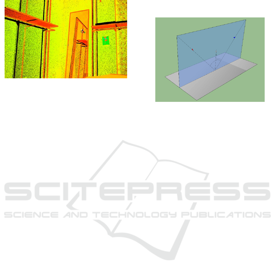
Figure 1: Laser scanning next to a mirror at a department
store (point cloud).
2 MOTIVATION
In experimental earthquake engineering the laser
scanners have been used in many applications (see
Takhirov, 2010; Mosalam, Takhirov, and Hashemi,
2009; Mosalam, Takhirov, and Park, 2014, as
representative examples). It is used for four-
dimensional tracking of the test specimen's condition
in three spatial coordinates and time. When a single
scanner is used, the object's rear surface is in shadow
zone and the points of the rear surface are not
collected. To acquire the point cloud of the object's
rear side two options can be used. In Option 1, several
scanners working in parallel can be deployed. In
Option 2, the same scanner can be moved to other
positions to cover the shadow zones. Option 1 is
expensive as it requires an investment in two or more
scanners, finding a way of triggering them
simultaneously, and a registration of the point clouds
collected by several scanners. The main shortcoming
of Option 2 is that it does not allow simultaneous
scans from both sides, and a registration of the laser
scans from many different points can be time
consuming. This paper introduces a novel approach
of using several mirrors strategically placed in respect
to a single scanner to cover the shadow zones with a
single scanner and from the same position.
3 GENERAL COMMENTS
ABOUT THE LIGHT
REFLECTION PROBLEM
For simplicity, let us assume that the coordinate
system is selected in such a way that the mirror is
located in the horizontal plane. We will assume that
the imperfections of the mirror are negligible and as
such, the incident and the reflected rays remain in the
same plane as presented in Figure 2.
Figure 2: Trajectories of incident beam and beam reflected
from horizontal surface remain in the same plane.
One of the main principles in optics is that the
incident and reflected angles will be the same in
respect to the normal of the plane from which the
reflection occurs (Lekner, 1987). Therefore, all
trajectories of the incident and reflected laser beams
will be in a plane that contains the focal center of the
scanner (emitting point) and the location of the point
measured by the laser scanner. As discussed above
this plane is orthogonal to the plane of the mirror.
4 EXPERIMENTAL SETUP AND
SUBSETS OF COLLECTED
POINT CLOUD
The quality of the reflected point cloud was
investigated in the following experimental setup.
Several tinted glass globes, two prismatic shapes (one
wooden block and one cardboard box) and several
high-definition laser targets (HDLT) were
strategically placed inside an experimental room. The
laser scanner was installed in such a way that all
objects were visible from the scanner’s location and
were visible in the mirror’s reflection. To minimize
the effect of the reflectivity of the shiny glass surface,
the globes were spray painted with a flat grey paint.
The mirror’s location in space was identified by using
three HDLTs that are commonly used for stitching the
laser scans. In addition, three HDLTs were placed on
the walls of the room. Twelve targets were placed on
a large piece of thick plywood. Special plywood with
a high flatness tolerance was selected for this purpose.
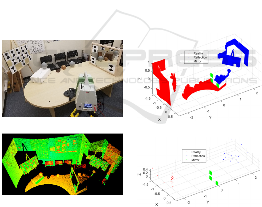
A photo of the experimental setup is presented in
Figure 3. The corresponding point cloud is presented
in Figure 4. The scans were performed with Scan
PHOTOPTICS 2021 - 9th International Conference on Photonics, Optics and Laser Technology
82
Station C10 (Leica Geosystems AG, 2011), Scan
Station P40 (Leica Geosystems AG 2019), both from
Leica Geosystems, Focus S-350 from FARO
Technologies Inc (FARO Technologies Inc., 2020)
and TX6 scanner form Trimble (Trimble, 2016). For
the purpose of this paper, the results for one of the
scanners (namely, Scan Station C10) are discussed in
more detail.
It is worth noting that usage of the HDLTs was
crucial for achieving the objectives of the paper.
Earlier it was observed that the mid-range (up to 200
m) laser scanners from Leica Geosystems produce a
noisier point cloud than a close-range high-accuracy
laser scanner (Takhirov, 2010). Nevertheless,
averaging the point cloud brings it much closer to the
actual surface. In addition, it was shown that while
the nominal accuracy of individual point cloud
acquisition is ±6 mm at 50 m range (Leica
Geosystems AG, 2011 and 2019) the accuracy of
HDLT’s acquisition is less than 1 mm (Takhirov,
2008). The high accuracy of the flat black and white
geometric patterns similar to the HDLTs used in this
paper was reported earlier by many other authors (see
Janßen et al, 2019 as a representative example).
Figure 3: Photo of experimental setup.
Figure 4: Corresponding point cloud.
The initial data manipulation was conducted in
Cyclone (Leica Geosystems AG, 2018). The acquired
point cloud was separated in three subsets. First, the
subset consisting of the point cloud excluding the
mirror reflection was separated. It was called
‘Reality’. Second, the subset consisting of the point
cloud behind the mirror surface was separated. It was
called ‘Reflection’. Third, the subset of the point
cloud corresponding to the HDLTs on the mirror’s
front surface was separated. It was called ‘Mirror’. To
simplify the data manipulation, the coordinate system
of the point cloud was changed in Cyclone [10] to
have all the vertices of the mirror’s targets in the plane
Y=0. After all these preparations, the subsets were
exported as ASCII files to be manipulated in the
Matlab [MathWorks, 2016] environment. All subsets
are presented in Figure 5. It was expected that a
geometric transformation corresponding to the mirror
reflection would result in consistent point clouds of
the objects with actual surfaces completed by
reflected point clouds. To improve the accuracy of
mirror transformation vertices of the high-definition
targets were used. The targets and their locations in
respect to the mirror are presented in Figure 6.
In Figure 5 and Figure 6, the points related to
Reality, Reflection and Mirror are presented in red,
blue and green colors, respectively.
Figure 5: Point clouds.
Figure 6: Vertices of targets.
A Novel Approach for Experimental Earthquake Engineering Utilizing Mirror Reflections of Point Clouds Collected by Laser Scanner
83
5 GEOMETRIC
TRANSFORMATION USED
FOR THE REGISTRATION OF
REAL AND REFLECTED
CLOUDS
The mirror transformation of the point clouds based
on the location of the front surface of the mirror
resulted in a large error between the real and reflected
targets. The error related to the assumption that the
reflective surface is located on the front side of the
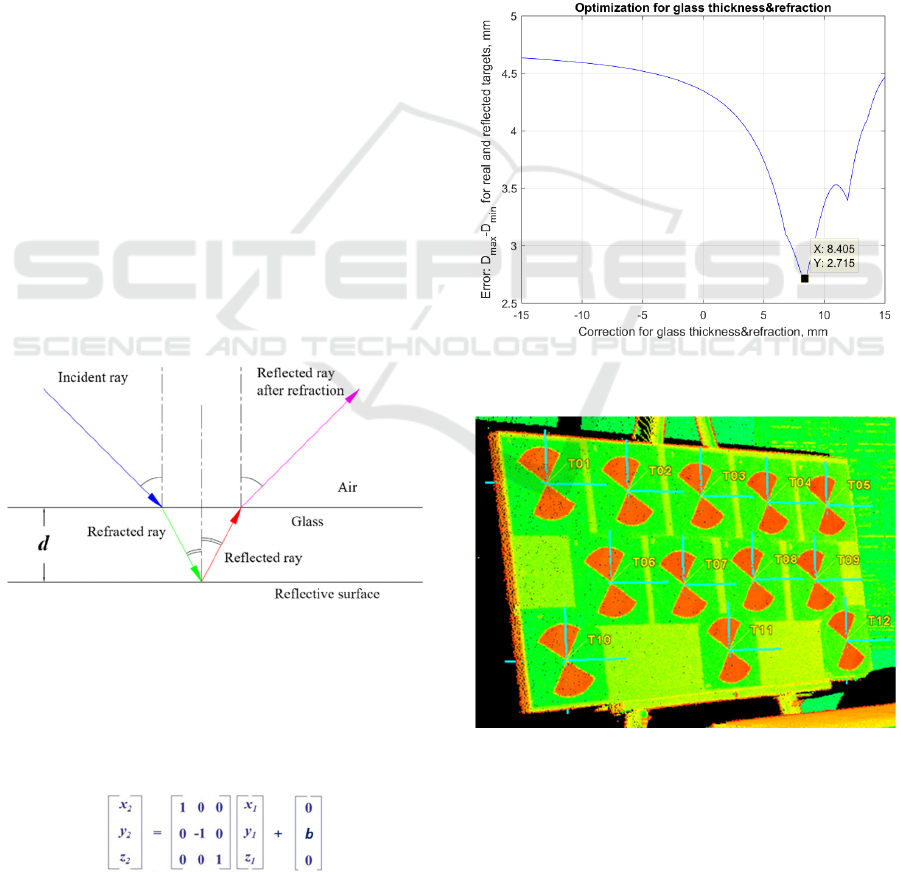
mirror. In reality, consumer grade mirrors are
manufactured as a large piece of glass with the
reflective surface on its rear side as presented in
Figure 7. When the laser beam comes into contact
with the front side of the glass it refracts and changes
its direction and velocity of propagation.
Subsequently, the refracted laser beam reflects from
the reflective surface and it refracts again while
exiting the glass layer. Therefore, an offset needs to
be introduced into the geometric transformation that
will account for the thickness of the glass layer, d, and
the refraction of the laser beams in the glass layer. It
is obvious that the offset, b, will depend on the
incidence angle of the incident laser beam. For the
purpose of the paper, this offset was estimated by
minimizing the distance between real and reflected
targets. To this extent, an effective thickness of the
glass that includes the refraction effect was obtained.
Figure 7: Mirror with a glass layer (consumer grade mirror).
The following procedure was used. To obtain a
transformed point cloud of Reflection, (x
2
, y
2
, z
2
), a
mirror geometric transformation was applied to
Reflection point clouds (x
1
, y
1
, z
1
) with an offset
vector of (0, b, 0):
The glass thickness and refraction correction factor,
b, was varied from 15 mm to -15 mm. For each value
of b, the distances between the real and reflected
targets were computed. The maximum variation of
these distances was estimated by subtracting the
minimum value from the maximum value. The result
presented in Figure 8 shows that the smallest error
occurs when b = 8.405 mm. The procedure was used
for the targets in close proximity to the mirror as
shown in Figure 9. This offset value was used in
combination with the mirror transformation to
compare reality and reflection point clouds. The
resultant registration is presented in Figure 10. All
targets in 3D space are shown in Figure 6a and errors
in the target locations are presented in Figure 11.
Figure 8: Minimization of error between real and reflected
targets.
Figure 9: Only HDLTs in close proximity to the mirror were
used for the optimization.
PHOTOPTICS 2021 - 9th International Conference on Photonics, Optics and Laser Technology
84
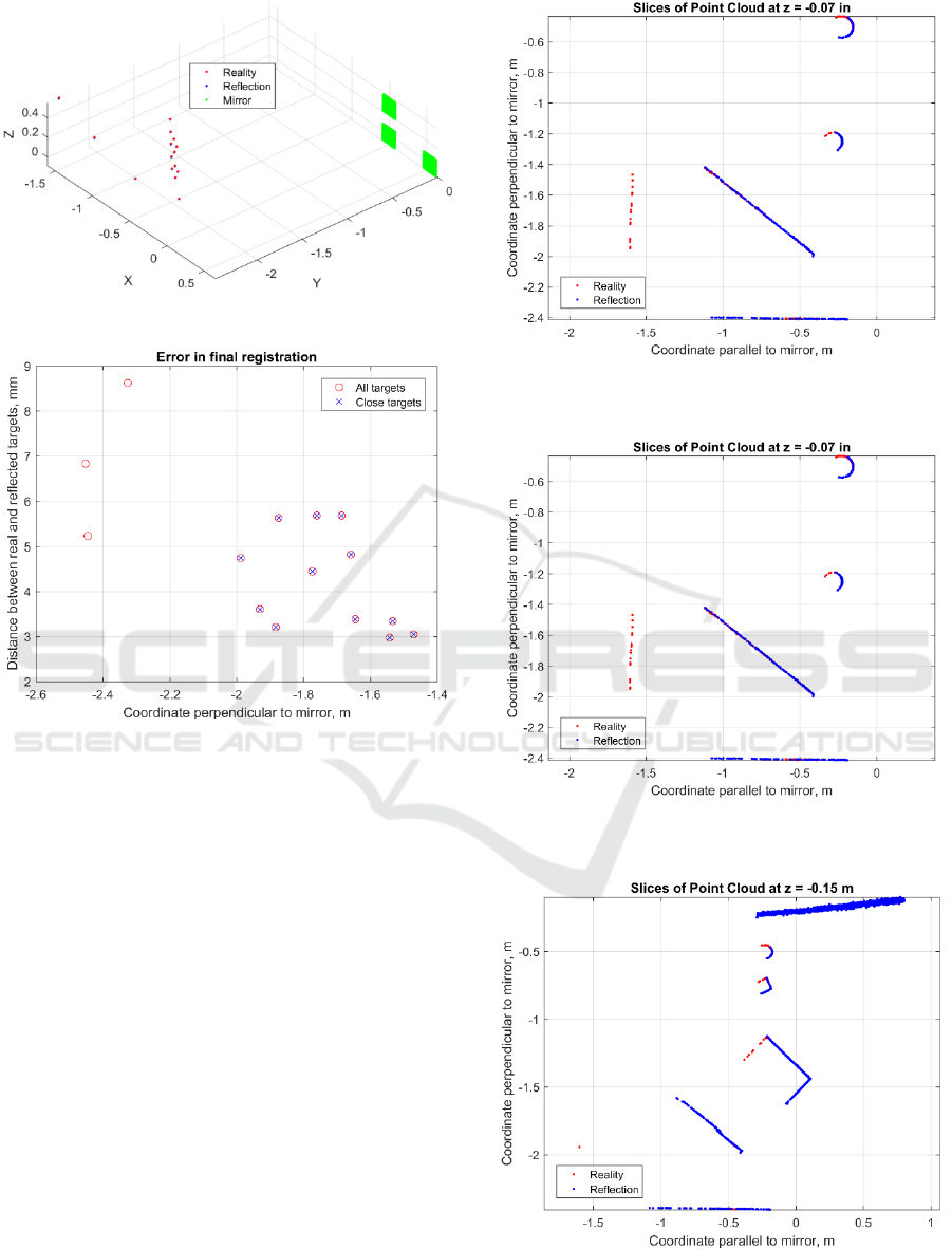
Figure 10: All targets in 3D space.
Figure 11: Distance between real and reflected targets:
close targets have smaller distance.
The final registration resulted in a reflected point
cloud with a reasonably good quality that
complemented the point cloud collected by the
scanner without the mirror. The overall view of the
real and reflected point clouds combined in the final
registration is presented in Figure 12. A horizontal
section of the same registration showing a close
matching of the two globes is presented in Figure 13.
Figure 14 presents another horizontal section of the
registration that shows closely matched point clouds
for both prismatic shapes and a globe. A good
correlation between point clouds of Reality and
Reflection relative to the walls of the room is
presented in Figure 15.
Figure 12: Registration of Reality and Reflection in 3D
space.
Figure 13: Horizontal slice of the registration at Z = -0.07m:
two globes, surface with targets, two walls.
Figure 14: Horizontal slice of the registration at Z = -0.15m:
a globe, two prismatic shapes, surface with targets, a wall.
A Novel Approach for Experimental Earthquake Engineering Utilizing Mirror Reflections of Point Clouds Collected by Laser Scanner
85
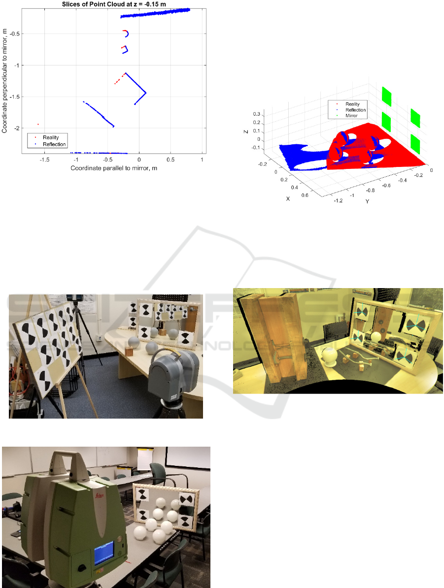
Figure 15: Horizontal section at Z = 0.62 m (two walls and
a plywood with targets).
The same approach was used for registering real point
clouds with the ones obtained from the reflection in
the laser scans obtained by the TX6 scanner (Trimble,
2016). A typical experimental setup with the TX6
scanner is presented in Figure 16. Figure 17 presents
the experimental setup with the P40 scanner, which
was also used in this study.
Figure 16: Experimental setup with TX6 scanner.
Figure 17: Experimental setup with P40 scanner.
This approach was also used for registering the real
point clouds with those reflected by the mirror in the
case of the Focus S-350 scanner too. A typical result
showing real and reflected point clouds stitched
together based on this approach are presented in
Figure 18.
Figure 18: Registration of real and reflected point clouds for
globes (Focus S-350 scanner).
This approach allows the registration of reflected
point clouds with the real ones for more complex and
irregular shapes as presented in Figure 19.
Figure 19: Laser scanning of complex shapes by utilizing
the mirror approach.
In addition to a regular scanning of the objects,
this approach can be used for 4D surface tracking of
test specimens during their deformation under a test.
If the position of the scanner is fixed for the duration
of the test, the registration between the reflected and
real point clouds needs to be done only once. The
latter makes the approach quite valuable and cost
effective for this kind of application and does not
require having several scanners to capture the shadow
zones.
The process of registration can be established
and/or mathematically verified by an analytical
formula based on geometry and the physics of
reflection and refraction of laser beams. This portion
of the research is ongoing and will be included in
future publications.
PHOTOPTICS 2021 - 9th International Conference on Photonics, Optics and Laser Technology
86

6 CONCLUSIONS
This paper investigates the point clouds obtained
from mirror reflections and quantifies the quality of
these data by estimating accuracy and reliability of
the reflected point cloud data. It is shown that the
accuracy of the reflected point cloud will depend on
the thickness of the front glass layer that is usually
present in consumer grade mirrors. In addition,
accuracy depends on the refraction effects and the
angle of incident beams. In the particular case where
the variation of the incident angles is limited, a
simplified correction factor can be introduced that
significantly improves the quality of the final
registration. The correction factor is obtained by
minimizing the error between the high-definition
targets visible with and without the mirror during
optimization of the registration process. In this case,
it is shown that the overall error of the registration is
less than 4 mm, which is acceptable for many
applications. When the deformed shape of a test
specimen is tracked in 3D over time (4D tracking),
the scanner’s position does not change and such, the
registration discussed above needs to be done only
once, let’s say for the very first scan of the specimen’s
undeformed shape.
ACKNOWLEDGEMENTS
Special thanks are due to the Pacific Earthquake
Engineering Research Center (PEER), UC Berkeley
for providing access to Scan Station C10. Also,
special thanks are due to Leica Geosystems for
providing access to Scan Station P40 which was
crucial for achieving the objectives of the paper. The
authors would like to thank FARO Technologies Inc
for providing access to Focus S-350. Special thanks
are due to Sensor Fusion and Monitoring
Technologies, LLC, for providing access to TX6
scanner from Trimble. The active participation of
Dr. Gregory Walsh of Leica Geosystems in
discussion of the project’s objectives is greatly
appreciated. Special thanks are due to Holly Halligan
of UC Berkeley for editing the paper.
REFERENCES
FARO Technologies Inc. (2020). https://www.faro.com/
products/construction-bim/faro-focus/.
Janßen, J., Medic, T., Kuhlmann H., and Holst, C. (2019).
Decreasing the Uncertainty of the Target Center
Estimation at Terrestrial Laser Scanning by Choosing
the Best Algorithm and by Improving the Target
Design. Remote Sensing. 11, 845; doi:10.3390/
rs11070845.
Leica Geosystems AG (2011). Leica ScanStation C10.
https://w3.leica-geosystems.com/downloads123/hds/
hds/ScanStation%20C10/brochures-datasheet/ Leica_
ScanStation_C10_DS_en.pdf.
Leica Geosystems (2018). Cyclone Version 9.2.1.
Leica Geosystems AG (2019). Leica ScanStation P40/P30
- High-Definition 3D Laser Scanning Solution.
https://leica-geosystems.com/en-us/products/laser-
scanners/scanners/leica-scanstation-p40--p30.
Lekner, John (1987). Theory of Reflection, of
Electromagnetic and Particle Waves. Springer. ISBN
9789024734184.
MathWorks (2016). Matlab Version R2016b.
Mosalam, K.M., Takhirov, S.M., and Hashemi, A., 2009.
Seismic Evaluation of 1940s Asymmetric Wood-Frame
Building Using Conventional Measurements and High-
Definition Laser Scanning, Earthquake Engineering
and Structural Dynamics, 38(10), 1175–1197.
Mosalam, K.M., Takhirov, S.M., and Park, S. (2014).
Applications of Laser Scanning to Structures in
Laboratory Tests and Field Surveys. Journal of
Structural Control and Health Monitoring, Volume 21,
Issue 1, pages 115–134, January 2014.
Takhirov, S.M. (2008). Applications of High-Definition
Laser Scanning Technology in Experimental
Earthquake Engineering. Presentation at HDS Leica
User’s Conference.
Takhirov, S.M. (2010). Laser Scanners in Structural
Assessment and FE modeling, 2010 Structures
Congress, Orlando, Florida, May 12-15, 2010.
Trimble (2016). https://geospatial.trimble.com/sites/
geospatial.trimble.com/files/2019-03/Datasheet%20-%
20Trimble%20TX6%20Laser%20Scanner%20-%20
English%20USL%20-%20Screen.pdf.
A Novel Approach for Experimental Earthquake Engineering Utilizing Mirror Reflections of Point Clouds Collected by Laser Scanner
87
