
SRCM: A Semi Formal Requirements Representation Model Enabling
System Visualisation and Quality Checking
Mohamed Osama
1 a
, Aya Zaki-Ismail
1 b
, Mohamed Abdelrazek
1 c
, John Grundy
2 d
and Amani Ibrahim
1 e
1
Information Technology Institute, Deakin University, 3125 Burwood Hwy, VIC, Australia
2
Information Technology Institute, Monash University, 3800 Wellington Rd., VIC, Australia
Keywords:
Requirement Representation, Requirement Modeling, Requirement Engineering, Quality Checking.
Abstract:
Requirements engineering is pivotal to the successful development of any given system. The core artifact
for such phase is the requirements specification document. Requirements can be specified in informal, semi-
formal, and formal notations. The majority of the requirements across many fields and domains are written
natural language. However, natural language is inherently ambiguous and imprecise and the requirements
cannot be automatically validated. Formal notations on the other hand enable automated testing and validation
but is only comprehensible by experts and requires rewriting the requirements. Semi-formal notations strikes
a good balance between comprehension and checking for several systems. However, the majority of the
existing representation models mandates the requirements to be (re)written to adhere to certain templates.
They also do not support automated checking. In this paper, we present SRCM –a semi-formal requirements
representation model based on a comprehensive requirements capturing model (RCM) that does not enforce
much limitations on how the requirements can be written. We also provide an automated approach to construct
SRCM from RCM. In addition to providing a unified visualisation of the system entities and relations between
the requirements key components, SRCM also enables automated quality checking on the requirements.
1 INTRODUCTION
Detecting quality issues (i.e., inconsistencies, incom-
pleteness and incorrectness) at an early stage, in sys-
tem requirements specifications, improves the quality
of the developed system. In addition, it minimises the
overall development time and cost (Kamalrudin et al.,
2011). Formal methods and model checking are used
for requirements verification in software engineering
to detect such issues(Ghosh et al., 2016; ?). To ben-
efit from these approaches, requirements should be
represented in a suitable formal notation. However,
requirements formalisation is a difficult task that re-
quires experience in both mathematics and the system
domain of interest (Buzhinsky, 2019; ?). Another re-
search direction is detecting quality issues at the semi-
formal representation level. Semi-formal require-
a
https://orcid.org/0000-0002-1580-6619
b
https://orcid.org/0000-0002-6940-0833
c
https://orcid.org/0000-0003-3812-9785
d
https://orcid.org/0000-0003-4928-7076
e
https://orcid.org/0000-0001-8747-1419
ments are typically represented in graphical notations
(i.e., helping users to better understand systems –
specially large ones). Existing techniques are limited
to detecting quality issues by comparing the semi-
formal model against a reference (e.g., system domain
or model repository (Kamalrudin et al., 2011)). This
is primarily because they are built upon either widely
known semi-formal models (e.g., UML) or on a pro-
posed model (e.g., (Kamalrudin et al., 2011)) that pro-
vides abstract view of the system (i.e, behavior, struc-
ture, etc.).
Complementary to existing work, we propose a
semi-formal model –system requirements capturing
model (SRCM)– visualising the system requirements
in a unified view. This model is designed to enable a
better understanding of textual requirements and the
relations among them, in addition to automatically de-
tecting a wide range of quality issues.
SRCM is an extension to requirement capturing
model (RCM) (Zaki-Ismail et al., 2020). RCM is
a comprehensive model developed for representing
behavioural system requirements by supporting their
key properties. RCM encapsulates semi-formal and
278
Osama, M., Zaki-Ismail, A., Abdelrazek, M., Grundy, J. and Ibrahim, A.
SRCM: A Semi Formal Requirements Representation Model Enabling System Visualisation and Quality Checking.
DOI: 10.5220/0010271202780285
In Proceedings of the 9th International Conference on Model-Driven Engineering and Software Development (MODELSWARD 2021), pages 278-285
ISBN: 978-989-758-487-9
Copyright
c
2021 by SCITEPRESS – Science and Technology Publications, Lda. All rights reserved

formal semantics. However, it is created to repre-
sent only one requirement and does not capture inter-
requirements relations. We build SRCM to aggregate
and unify the given system requirements (RCMs) in
a model that shows the relations among them and en-
ables the automated detection of quality issues.
2 RELATED WORK
The main three approaches for representing require-
ments in semi-formal notations are: controlled nat-
ural language (CNL), graphical representations, and
mathematical representations (Marko et al., 2015).
CNL aims at writing syntactically correct require-
ments adhering to a given set of templates and/or
boilerplates (De Gea et al., 2012). Several types of
templates and boilerplates (e.g., the EARS approach
(L
´
ucio et al., 2017)) are present in the literature.
Farfeleder et al. (Farfeleder et al., 2011) devel-
oped an approach relying on boilerplates along with
a domain ontology. A case study in (St
˚
alhane and
Wien, 2014) provides an evaluation of their work.
This study showed that the use of such tools helped
’develop a requirement set that is consistent and un-
ambiguous (St
˚
alhane and Wien, 2014). Such ap-
proaches however, require the presence of an ontol-
ogy.
In (Kamalrudin et al., 2017)(Kamalrudin et al.,
2011), MaramaAIC tool is proposed to support con-
sistency management and requirements validation us-
ing semi-formal essential use cases (EUC). First,
the use case models are extracted from the NL-
requiremnts. Then, the abstract interactions of the
EUC are compared to a repository of patterns. Con-
sequently, a mismatch indicatea a quality issue.
Nguyen et. al. in (Nguyen et al., 2016) proposed
an ontology-based integrated framework for verifying
goal use cases. They developed a tool called GUI-
TAR. It takes textual requirements and transforms
them into Goal use-cases for automatic reasoning and
issues detection. A similar approach is presented in
(Corea and Delfmann, 2017) for business processes
verification, where business rules are specified as a
logic program, and an ontology reasoner is used to
discover model elements violating these rules.
Verification of UML Class/OCL model through
(semi)formal notations has been discussed in the liter-
ature. Truong et. al. (Truong and Souqui
`
eres, 2004)
presented the transformation of UML class model into
the B method. Then, the consistency of the class
model is verified against UML well-formedness rules.
In which, the rules are transformed into the invariant
of B abstract machine. Similarly, Cabot et. al. (Cabot
and Teniente, 2009) proposed an incremental verifi-
cation of UML Class/OCL model through (Constraint
Satisfaction Problem) CSP. They illustrated that veri-
fication of constraints after every structure event (En-
tity Insertion, Attribute update, Entity Deletion, etc.)
is costly and inefficient. They proposed the PSEs con-
cept (Potential Structure Events). PSEs are events
causing constraints violation. In this technique, PSEs
for every integrity constraint are recorded and in-
stances of entities and relationships are incrementally
verified.
Model Based Systems Engineering (MBSE) like
SysML (Mhenni et al., 2014) and Capella (Roques,
2016) languages are popularly used in multiple indus-
tries (Azzouzi et al., 2019). However, they encounter
considerable limitations concerning formal handling
of requirements, and thus the automatic verification
and validation. In addition, there is a wide gap be-
tween the early design phases (e.g., requirement cap-
ture) and the subsequent detailed design phases (i.e.,
when disciplinary modeling and simulation are in-
volved) (Azzouzi et al., 2019). A common issue
within the highlighted semi-formal notations tools
and approaches is that no automated checking support
is provided (Azzouzi et al., 2019)
3 REQUIREMENTS CAPTURING
MODEL (RCM)
RCM is a semi-formal representation model proposed
in (Zaki-Ismail et al., 2020) for capturing behavioural
system requirements. RCM defines the the compo-
nents constituting any NL-requirement specification
and their breakdowns.
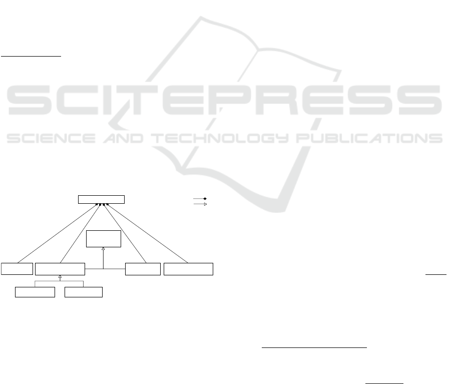
Figure 1 provides the compact high level architec-
ture of RCM.
System
Requirement
Primitive
Requirement
Req Scope
Req Tr igger
Req Condition
Req Action
1..*
1..*
0..*
0..*
0..*
Figure 1: Compact High-level Architecture of RCM.
RCM defines system requirements as a set of re-
quirements R. Each requirement R
i
, may have one
or more primitive requirements PR where {R
i
= <
PR
n
> and n>0}. Each PR
j
represents only one sen-
tence, and may contain conditions, triggers, actions
and scope – in the NL-requirement. RCM captures
primitive requirements of the same requirement sep-
arately and stores them as one unit. A primitive re-
quirements consists of four main components:
SRCM: A Semi Formal Requirements Representation Model Enabling System Visualisation and Quality Checking
279
• Trigger: an event that automatically initiates/fires
action(s) whenever it occurs (e.g.,when emer-
gency button is pressed).
• Condition: constraints that should be checked ex-
plicitly by the system to allow action(s) to happen
(e.g., if aircraft data is unavailable).
• Scope: provides the circumstances under which:
(1) condition(s) and trigger(s) shall be valid –
called ”pre-conditional scope”, and (2) action(s)
should occur – called action scope.
• Action: holds the task that should be executed in
response to trigger(s) and/or constrained by con-
dition(s) (e.g., the communication system shall
sustain telephone contact with 10 callers). A
primitive requirement with an action component
only is a factual rule expressing system factual in-
formation (e.g., ”The duration of a flashing cycle
is 1 second”).
The core part of these components is the Predi-
cate including: the operands, the operator and nega-
tion flag/property. For example, in the condition
If X exceeds Y, ”X” and ”Y” are the operands and
”exceeds” is the operator.
RCM avoids loss of information, by preserving
logical relations among components of the same type
in the interior nodes of a tree structure (the most suit-
able structure), where the components themselves are
stored in the leaves.
4 SYSTEM REQUIREMENTS
CAPTURING MODEL (SRCM)
Sys RCM
Sys Entity Sys Pre-condition Sys Action Sys Action source
System
Component
Sys Condition Sys Trigger
1..*
1..*
1..*
1..*
Inheritance Relation
Aggregation Relation
Figure 2: High-level Architecture for SRCM.
SRCM is a graph-based extension of RCM that unifies
the representation of all the requirements of a given
system in one integrated model. It enables (1)visu-
alising the relations among system requirements, and
(2) detecting quality issues in an automated manner.
SRCM consists of four main components: system en-
tities, system pre-conditions, system actions and ac-
tion sources as indicated in Figure 2.
1. System Entities are all the unique domain entities
for a given system. For each entity, the following
properties are defined:
• Domain Name: the name used to refer to such
entity within the given system
• Value Type: the type of the values assigned
to this entity. It may be either atomic (e.g.,
number, boolean) or system dependent (system
value).
• Possible Values: list of the system values in
case the value type is system dependent.
• Affecting Entities: system entities that may
cause a change to this entity when they change.
• Affected Entities: in contrast to the previous
list, it contains the system entities that may be
changed as a result of a change in this entity.
2. Pre-conditions hold the prerequisite(s) required
for an action to occur. A pre-condition may
be a system-condition or a system-trigger. Pre-
condition are modeled as system components in
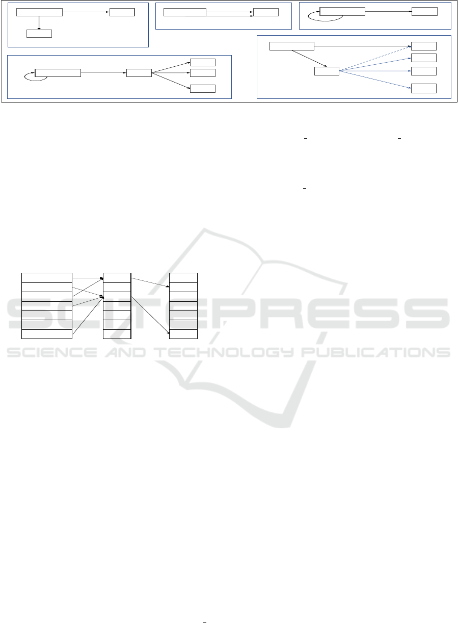
SRCM as indicated in Figure 2. Figure 3 shows
the architecture of different system component
structures. The system component structurally
visualises the relations between the contributing
system entities in the component, by showing
links to: (1) the primary entity (the entity upon
which the system component is defined) and (2)
the value source entity (the entity where the sys-
tem component gets its value from). A value may
have one of the following structures:
• External Value: the primary entity is compared
to the value of another entity (e.g., If X exceeds
Y) as in Figure 3.(a).
• Internal Value: the primary entity is compared
to a related domain dependent system value
(e.g., If the Regulator Mode equals [NOR-
MAL]) as in Figure 3.(b).
• Atomic Value: the primary entity is compared
to atomic values as numbers, boolean, etc (e.g.,
If the Regulator Interface Failure is set to False)
as in Figure 3.(c).
• Aggregated Value: the primary entity is com-
pared against the aggregation of some system
entities that may include the primary entity it-
self (e.g., if the calculated distance is less than
(the current speed / 3) * t2) as in Figure 3.(d).
• Aggregated Entity: the primary entity is the ag-
gregation of multiple entities that are compared
to an atomic value (e.g., if (S1 + S2)
exceeds 3).
If the aggregated entities are assessed against
a system value then it would match the aggre-
gated value structure in Figure 3.(e).
MODELSWARD 2021 - 9th International Conference on Model-Driven Engineering and Software Development
280
Sys Comp
E
1
E
2
Primary Entity
value
(a) External value
Sys Comp
E
1
Primary Entity
value
(b) Internal value
Sys Comp
E
1
Primary Entity
value
(c) Atomic value
Sys Comp
E
1
AV
Primary Entity
Aggregated
value
(d) Aggregated value
E
2
E
3
E
n
.
.
.
value
AE
(e) Aggregated entity
E
1
E
2
E
k
Sys Comp
.
.
.
Primary Entity
value
Aggregated
Entities
Figure 3: Different structures of a system component.
3. Action represents the action or change that should
happen in response to its precondition(s) being
satisfied. It corresponds to RCM requirements ac-
tion. An action can be in any of the various struc-
tures applicable to a pre-condition as in Figure 3.
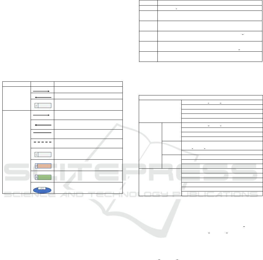
4. Action Source connects each action to its corre-
sponding preconditions within the system as in-
dicated in Figure 4. It also holds any relations
(e.g. AND/OR) between the pre-conditions of an
action.
Pre-cond
1
Pre-cond
2
Pre-cond
3
.
.
.
Pre-cond
m
AS
1
.
AS
i
.
.
.
AS
k
A
1
A
2
A
3
.
.
.
A
r
System Pre-
conditions
Action
Sources
System
Actions
Figure 4: System action sources.
5 SRCM CONSTRUCTION
APPROACH
SRCM is constructed by extracting the required in-
formation from each RCM structure. The three main
goals of the automatic construction are: (1) iden-
tify unique system entities, (2) identify unique system
components and (3) construct system level mapping.
These goals are achieved incrementally through an it-
erative approach.
5.1 Entities Identification
Each RCM structure is addressed apart to extract all
the system entities from each component. To achieve
this, the arguments of each component in an RCM
structure are classified into entities and values based
on domain and English characteristics as follows:
• Entities are either (1) domain variables following
a special format (e.g., preceded by ”RCMVAR ..”,
”RCMCAL ..” and ”RCMTech ..”), or (2)
expressed in English noun phrases.
• Values, similarly to entities, are either (1) domain
values with a special format (e.g., preceded by
”RCMVAL ..” in RCM), or (2) expressed in En-
glish adjective, adverb ,or cardinal number.
The extracted entities are then added to the entire
system entities list in case they are new (not previ-
ously extracted from another component). Accord-
ing to the domain variables, unique items are added
to system entities. On the other hand, English enti-
ties should pass similarity checking with the existing
English entities in system entities to ensure unique-
ness. Each unique entity, domain/English entity, is
assigned a unique Id. All encountered English terms
are grouped in a side structure, similar terms referenc-
ing the same entity, for similarity checking purpose.
5.2 Components Identification
The aim of this process is identifying the unique sys-
tem component sets (pre-conditions and actions sets).
First, the system component type of the RCM com-
ponent under investigation is identified based on the
RCM component type (i.e., condition −→ system
condition, trigger −→ system trigger and action −→
system action). Second, the component breakdowns,
primary entity and the appropriate value structure, are
identified. RCM components provide LHS (left hand
side), RHS (right hand side) and relation(s) (e.g., in
the component ”the rain signal is ON”, the LHS: :the
rain signal”, the RHS: ”ON”, and the rel: ”=”).
The relations controlling the entities (i.e., aggre-
gating relation) and the component (e.g., = 6=<>≤≥)
are mapped from the RCM component. After the
complete construction of a system component, if the
constructed component is new, it will be added to the
relevant unique set and assigned a unique id.
5.3 Relational Mapping
In this process, a requirement can be defined on the
system level. Since SRCM consists of unique sets
SRCM: A Semi Formal Requirements Representation Model Enabling System Visualisation and Quality Checking
281

of system components, actions, and preconditions, a
mapping is required to indicate which pre-conditions
cause which action(s) (i.e., representing one require-
ment sentence done through action sources as dis-
cussed earlier). The mapping can be accomplished
in a compact manner by storing the unique keys, each
corresponding to a unique system component, of the
preconditions and actions constituting one require-
ment sentence. In addition, The logical relations,
AND/OR, among multiple system components of the
same type (e.g., conditions, triggers, .etc) within the
same requirement sentence are captured and mapped
from the RCM structure.
6 QUALITY CHECKING
This section illustrates how SRCM facilitates de-
tecting requirements redundancy, ambiguity, incon-
sistency, and incompleteness quality issues (ranked
as the top attributes affecting requirements quality
(G
´
enova et al., 2013; Anuar et al., 2015; Kocerka
et al., 2018)).
Redundancy: is when the same requirement appears
more than once in the requirements specification doc-
ument (Lami et al., 2004). The problem is not in
the redundancy itself, but in the consequences of hav-
ing redundancy, especially when the document is up-
dated. For example, if a requirements document has
two duplicate requirements in two places and only
one of them is altered, the document will be incon-
sistent. In addition, because requirements are mostly
written by more than one engineer, there is also the
prospect of having the same requirement stated dif-
ferently (e.g., ”If X exceeds Y, Z shall be set to true”
and ”transition Z to true, if X is larger than Y”). Such
case is not easily detectable at the informal level of
requirements. However, it can be detected in SRCM
just by locating repeated action sources. The reason
behind that is, detected duplicate system components
of the same type (detected during the construction)
are stored only once in SRCM and are assigned with
unique keys. Consequently, action sources of redun-
dant requirements will map to the same keys.
Ambiguity: within requirements can lead to confu-
sion, wasted efforts, and unnecessary rework. Am-
biguity has a set of indicators such as vagueness,
subjectivity, optionality, implicity, .etc (Lami et al.,
2004). Currently, vagueness can be detected dur-
ing the construction of SRCM. Vagueness means that
the requirement sentence contains word(s) with more
than one quantifiable meaning (Lami et al., 2004).
Thus, such issue can be flagged whenever a descrip-
tive value is found during the construction process.
Inconsistency: is the case where two or more require-
ments contradict one another (Lami et al., 2004). This
issue can be detected through SRCM as follows:
• domain-independent approach: in this approach,
inconsistencies can be detected when entities as-
signed/compared to values with different types.
Assume the following two requirements ”If X ex-
ceeds Y, set X to True. Y is initialized with 2”.
There is an inconsistency because X is compared
to an argument with a number type and assigned
to value with a boolean type. Such type of incon-
sistencies can be easily detected through SRCM
construction. The value type of each entity is re-
alized from the given set of requirements. In case
that a contradicting type is encountered for an al-
ready type-bound entity, an inconsistency issue
is flagged for that entity highlighting the require-
ments contributing to the problem.
• domain-dependent approach: entities and values
of the processed sentences are compared to the
given domain ontology. In case of a mismatch
(e.g., encountering an ineligible value type), the
broken requirement sentence is flagged highlight-
ing the mismatch. This type of checking is op-
tional –can be achieved once the system domain
is available.
Incompleteness: Incompleteness is considered to be
the most difficult of the specification attributes to de-
fine and detect (Lami et al., 2004). SRCM can help
in detecting missed information/arguments from a re-
quirement component. Assume the following exam-
ple ”If X is True, Y shall be set”. In such example, it
is not determined to what value ”Y” shall be set. In
case that ”Y” is a number type, then ”Y” is eligible
to many variations. Such type of incompleteness can
be detected through SRCM when a component com-
prises at most one argument.
7 SRCM VISUALIZATION
The second goal of SRCM is visualising requirements
in an integrated and unified view. SRCM can provide
two different views of the system.
• Entities View: provides the complete depen-
dency of either the entire requirements entities or
only a selected subset. These dependencies show
the effect of a change occurring in a given en-
tity on other entities. The benefit of this view is
providing a focused interaction map of the (sub-
set)requirements of interest. SRCM can provide
this view based on the aggregated information, af-
fecting and affected entities of each entity, for the
MODELSWARD 2021 - 9th International Conference on Model-Driven Engineering and Software Development
282
system entities discussed before.
• Requirements View: presents the SRCM com-
ponents and their relations for either the entire re-
quirements or only a selected subset of require-
ments. Representing textual requirements in a vi-
sual structure increases their expressiveness for
all requirements stakeholders. Moreover, detected
quality issues can be highlighted on the visualised
view.
Table 1 provides the graph notations of both views.
Table 1: Graphical Representation of SRCM Views.
View Type Notation Role
Entities View
in arrow: represents affecting entities
out arrow: represents affected entities
E
represents System Entity
Requirements
View
in arrow: represents a contributing pre-
condition in an action source
out arrow: represents a response action
of an action source
solid line: represents the primary entity
of a system component
dashed line: represents the value source
of a system component
E
represents System Entity
P
represents System Pre-Condition (Trig-
ger/Condition)
A
represents System Action
AS
represents System Action sources
8 CASE STUDY
The case study used refers to a hand crafted set of
requirements for an elevator system. An elevator sys-
tem is the service by which people can transfer from
one building level to another. Usually in an eleva-
tor service a client can request an elevator, command
a specific level, close/open the door and alert emer-
gency. In order to show how SRCM can be con-
structed, and how it represents the requirements in
a unified integrated view, the results obtained with
SRCM are presented for six individual requirements
(manually visualised) in Table 2. Such requirements
are developed with the following considerations (1)
reflect the proposed cases of quality issues and (2)
illustrate construction and visualisation aspects. For
each, requirement, we discuss the SRCM construc-
tion process, and the quality issues detected. Finally,
we present the corresponding requirements and enti-
ties views supported by a demonstration of the details
in each view.
Table 2: Elevator Requirements.
Req-Id Requirement Text
Req1 <weight thr> is initialized to 1000
Req2 When the direction status is [Up] or [down], the elevator
motion status shall be changed
Req3 When the direction status is false, the elevator motion sta-
tus shall be transitioned to [Idle].
Req4 If the weight of the elevator exceeds <weight thr>, the
elevator motion status shall be [Idle].
Req5 The elevator motion status shall be set to [Idle], if the
weight of the elevator is larger than <weight thr>.
Req6 If the weight of the elevator is heavy, the alert light shall
be set to true.
The final SRCM breakdowns reflecting the eleva-
tor requirements are presented in Table 3.
Table 3: SRCM Breakdowns of Requirements in Table 2.
SRCM BreakDowns
System Entities
E1: RCMVAR weight thr
E2: the direction status
E3: the elevator motion status
E4: the weight of the elevator
E5: the alert light
System
Components
System-
Actions
A1: RCMVAR weight thr = 1000
A2: the elevator motion status shall be changed
A3: the elevator motion status shall = [Idle]
A4: the alert light shall = true
System-
Condition
C1: the weight of the elevator > RCM-
VAR weight thr
C2: the weight of the elevator = heavy
System-
Trigger
T1: the direction status = [Up]
T2: the direction status = [Down]
T3: the direction status = false
Action Sources
AS1: [][][A1]
AS2: [T1,T2][][A2]
AS3: [T3][][A3]
AS4: [][C1][A3]
AS5: [][C1][A3]
AS6: [][C2][A4]
The corresponding conducted analysis, reasoning,
and tracing for each requirement are as follows:
• Req1: this requirement is stored in RCM as an ac-
tion component. In which, (1) <weight thr> is
replaced with ”RCMVAR weight thr since” it is
a domain variable and (2) ”is initialized to” de-
tected as ”=” relation. By processing this com-
ponent, one system entity is detected ”RCM-
VAR
weight thr” (identified with the key ”E1”
and marked as the primary entity to the compo-
nent). The type of the detected entity is identi-
fied as Number since it is assigned a value ”1000”
tagged as cardinal number.
• Req2: is decomposed into three components in
RCM ”When the direction status is [Up]”, ”When
the direction status is [down]” and ”the elevator
motion status shall be changed”. The first two
components, classified as triggers, are mapped to
system triggers in SRCM and the last one is an
action mapped to system action. This sentence
produces two system entities: (1) ”the direction
status” with the key ”E2”, possible values {[Up],
[down]}, and type ”SystemValue”; and (2) ”the
SRCM: A Semi Formal Requirements Representation Model Enabling System Visualisation and Quality Checking
283
elevator motion status” with the key ”E3”. The ac-
tion component is marked as incomplete because
it contains only one argument in addition to the
relation (i.e, the value of change for ”the elevator
motion status” is unknown). ”E2” is stored as an
Affecting entity in ”E3” since any change in ”E2”
can cause a change in ”E3”. In addition, ”E3” is
stored as an Affected entity in ”E2”.
• Req3: here, RCM has two components: trigger
and action mapped to system trigger and system
action in SRCM respectively. The sentence results
in two entities: (1) ”the direction status” with the
value ”false” and type ”Boolean”. The entity is
already identified before with the key ”E2”, but
an inconsistency case is detected due to the types
conflict ”Boolean” and ”SystemValue”. (2) ”the
elevator motion status” is already recognised be-
fore with the key ”E3”, but it is assigned the type
”SystemValue” and the value ”[Idle]” here.
• Req4: this sentence has two RCM components
condition mapped to system condition and action
mapped to system action in SRCM. These compo-
nents provide only one new entity ”the weight of
the elevator” and two previously detected entities
”RCMVAR weight thr” ;and the ”elevator motion
status”. The entity ”the weight of the elevator” is
added to system entities with the key ”E4” and
type Number because it is compared against an
entity with type Number. Similarly to Req2, ”E1”
and ”E4” are stored as Affected entities in ”E3”
and ”E3” is stored as an Effected entity at ”E4”
and ”E1”.
• Req5: the sentence is a paraphrasing for Req4.
Thus, it does not add any new components or en-
tities to the constructed SRCM.
• Req6: the requirement has two RCM components:
condition mapped to system condition and action
mapped to system action. Only one entity ”the
alert light” is new and added to system entities
with the key ”E5” and the type ”Boolean”. In ad-
dition, the system condition ”If the weight of the
elevator is heavy” is flagged as ambiguous since
it comprises a vague value ”heavy”. Finally, ”E4”
is stored as an Affecting entity in ”E5” and ”E5”
is stored as an Affected entity in ”E4”.
The relations ”is initialized to”, ”is”, ”shall be
transitioned to”, ”exceeds”, ”shall be”, ” shall be set
to” and ”is larger than” are transformed to ”=”, ”=”,
”=”, ”>”, ”=”, ”=” ,and ”>” respectively in RCM.
This helps us detect the unique system components as
indicated in Table 3.
Finally, an action source for each requirement is
created (including the redundant one) and assigned a
unique key and instantiated with three lists compris-
ing the keys of the contributing conditions, triggers
and action in the corresponding requirement as indi-
cated in Table 3. After that, action sources with the
same action keys for the three lists are marked as re-
dundant (e.g., Req4 and Req5 flagged as redundant).
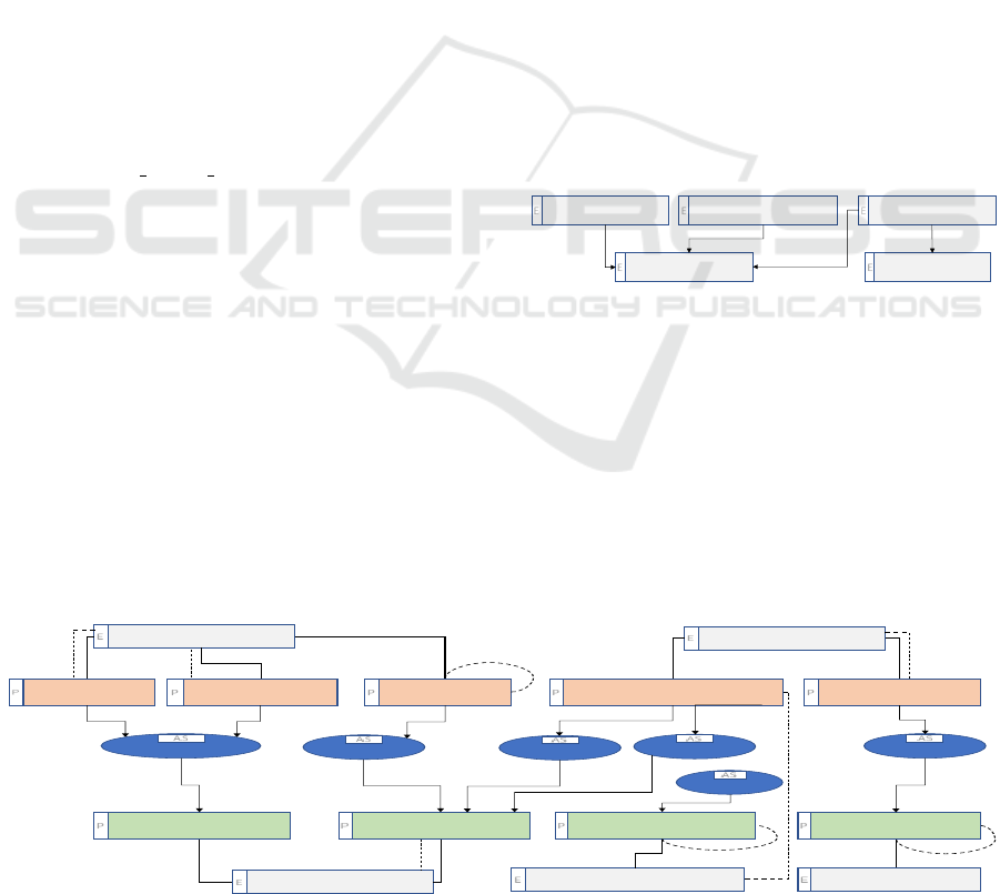
The requirements view and entities view of the
elevator six requirements are shown in Figure 5 and
Figure 6 respectively. This abstraction can help the
user figure out missing requirements because any
missing relation between the entities can be spotted.
In Figure 6, it can be noticed that, ”E3” is sensitive to
”E1”, ”E2” and ”E4”; and ”E5” is sensitive to ”E4”.
E1: RCMVAR_weight_thr
E
E2: the direction
status
E
E3: the elevator
motion status
E
E4: the weight of the
elevator
E
E5: the alert light
E
Figure 6: Entities View of Requirements in Table 2.
9 CONCLUSION
In this paper, we propose a graph-based semi-formal
requirements representation model (SRCM) that fa-
cilitates the visualisation of system requirements and
the relations among requirements components and
system entities. It also allows for quality checks
to be automatically applied over the automatically
E1: RCMVAR_weight_thr
E
E2: the direction
status
E
E3: the elevator
motion status
E
E4: the weight of the
elevator
E
E5: the alert light
E
T1: the direction
status = [Up]
P
T2: the direction
status = [Down]
P
T3: the direction
status = false
P
C1: the weight of the elevator
> RCMVAR_weight_thr
P
C2: Ithe weight of the
elevator = heavy
P
A3: the elevator motion
status shall = [Idle]
P
A2: the elevator motion
status shall be changed
P
A4: the alert light shall
= true
P
A1: RCMVAR_weight_thr
= 1000
P
AS2:T1 or T2
AS
AS3:T3
AS
AS4:C1
AS
AS5:C1
AS
AS6:C2
AS
AS1:
AS
Figure 5: Requirements View of Requirements in Table 2.
MODELSWARD 2021 - 9th International Conference on Model-Driven Engineering and Software Development
284

constructed model views. The intrinsic structure of
SRCM enables detecting wider range of quality is-
sues (i.e., ambiguity, incompleteness, incorrectness
and inconsistencies) compared to existing approaches
– with far less effort compared to formal methods. It
also keeps the requirements comprehensible by non
technical stakeholders and even enhances the expres-
siveness of the requirements by showing a unified
view of the system. We illustrated the construction
and visualisation of SRCM using a case study high-
lighting how some quality issues can be detected.
REFERENCES
Anuar, U., Ahmad, S., and Emran, N. A. (2015). A sim-
plified systematic literature review: Improving soft-
ware requirements specification quality with boiler-
plates. In 2015 9th Malaysian Software Engineering
Conference (MySEC), pages 99–105. IEEE.
Azzouzi, E., Jardin, A., Bouskela, D., Mhenni, F., and Cho-
ley, J.-Y. (2019). A survey on systems engineering
methodologies for large multi-energy cyber-physical
systems. In 2019 IEEE International Systems Confer-
ence (SysCon), pages 1–8. IEEE.
Buzhinsky, I. (2019). Formalization of natural language re-
quirements into temporal logics: a survey. In 2019
IEEE 17th International Conference on Industrial In-
formatics (INDIN), volume 1, pages 400–406. IEEE.
Cabot, J. and Teniente, E. (2009). Incremental integrity
checking of uml/ocl conceptual schemas. Journal of
Systems and Software, 82(9):1459–1478.
Corea, C. and Delfmann, P. (2017). Detecting compliance
with business rules in ontology-based process model-
ing.
De Gea, J. M. C., Nicol
´
as, J., Alem
´
an, J. L. F., Toval, A.,
Ebert, C., and Vizca
´
ıno, A. (2012). Requirements en-
gineering tools: Capabilities, survey and assessment.
Information and Software Technology, 54(10):1142–
1157.
Farfeleder, S., Moser, T., Krall, A., St
˚
alhane, T.,
Omoronyia, I., and Zojer, H. (2011). Ontology-driven
guidance for requirements elicitation. In Extended Se-
mantic Web Conference, pages 212–226. Springer.
G
´
enova, G., Fuentes, J. M., Llorens, J., Hurtado, O., and
Moreno, V. (2013). A framework to measure and im-
prove the quality of textual requirements. Require-
ments engineering, 18(1):25–41.
Ghosh, S., Elenius, D., Li, W., Lincoln, P., Shankar, N.,
and Steiner, W. (2016). Arsenal: automatic require-
ments specification extraction from natural language.
In NASA Formal Methods Symposium, pages 41–46.
Springer.
Kamalrudin, M., Hosking, J., and Grundy, J. (2011). Im-
proving requirements quality using essential use case
interaction patterns. In Software engineering (ICSE),
2011 33rd international conference on, pages 531–
540. IEEE.
Kamalrudin, M., Hosking, J., and Grundy, J. (2017). Mara-
maaic: tool support for consistency management and
validation of requirements. Automated software engi-
neering, 24(1):1–45.
Kocerka, J., Krze
´
slak, M., and Gałuszka, A. (2018).
Analysing quality of textual requirements using nat-
ural language processing: A literature review. In 2018
23rd International Conference on Methods & Models
in Automation & Robotics (MMAR), pages 876–880.
IEEE.
Konrad, S. and Cheng, B. H. (2005). Real-time specifica-
tion patterns. In Proceedings of the 27th international
conference on Software engineering, pages 372–381.
ACM.
Lami, G., Gnesi, S., Fabbrini, F., Fusani, M., and Trentanni,
G. (2004). An automatic tool for the analysis of nat-
ural language requirements. Informe t
´
ecnico, CNR
Information Science and Technology Institute, Pisa,
Italia, Setiembre.
L
´
ucio, L., Rahman, S., bin Abid, S., and Mavin, A. (2017).
Ears-ctrl: Generating controllers for dummies. In
MODELS (Satellite Events), pages 566–570.
Marko, N., Leitner, A., Herbst, B., and Wallner, A. (2015).
Combining xtext and oslc for integrated model-based
requirements engineering. In 2015 41st Euromicro
Conference on Software Engineering and Advanced
Applications, pages 143–150. IEEE.
Mhenni, F., Choley, J.-Y., Penas, O., Plateaux, R., and Ham-
madi, M. (2014). A sysml-based methodology for
mechatronic systems architectural design. Advanced
Engineering Informatics, 28(3):218–231.
Nguyen, T. H., Grundy, J. C., and Almorsy, M. (2016).
Ontology-based automated support for goal–use case
model analysis. Software quality journal, 24(3):635–
673.
Roques, P. (2016). Mbse with the arcadia method and the
capella tool.
St
˚
alhane, T. and Wien, T. (2014). The dodt tool applied
to sub-sea software. In 2014 IEEE 22nd Interna-
tional Requirements Engineering Conference (RE),
pages 420–427. IEEE.
Truong, N.-T. and Souqui
`
eres, J. (2004). An approach for
the verification of uml models using b. In Proceed-
ings. 11th IEEE International Conference and Work-
shop on the Engineering of Computer-Based Systems,
2004., pages 195–202. IEEE.
Zaki-Ismail, A., Osama, M., Abdelrazek, M., Grundy, J.,
and Ibrahim, A. (2020). Rcm: Requirement capturing
model for automated requirements formalisation.
SRCM: A Semi Formal Requirements Representation Model Enabling System Visualisation and Quality Checking
285
