
Inspection of Industrial Coatings based on Multispectral BTF
Ryosuke Suzuki
1
, Fumihiko Sakaue
1
, Jun Sato
1
, Ryuichi Fukuta
2
, Taketo Harada
3
and Kazuhisa Ishimaru
4
1
Nagoya Institute of Technology, Gokiso Showa, Nagoya, Japan
2
DENSO Electronics Corporation, 1-21 Miyama, Shinpukujicho, Okazaki, Japan
3
DENSO Corporation, 1-1, Showa-cho, Kariya, Japan
4
SOKEN Inc., 1-1, Showa-cho, Kariya, Japan
Keywords:
Multispectral BTF, Bidirectional Texture Function, Bidirectional Reflectance Distribution Function,
One-class Classifier.
Abstract:
In this paper, we propose a method to inspect coatings of industrial products in a factory automation system.
The coating of industrial products is important because the coating directly affects the impression of the
product, and a large amount of cost is spent on its inspection. Because lots of colors are used in the coating
of industrial products, as well as there are various surface treatments such as matte and mirror finishes, the
appearance of these products varies hugely. Therefore, it is difficult to obtain the properties of the surfaces by
ordinary camera systems, and thus, they are inspected manually in the current system in most cases. In this
paper, we present a method of representing surface properties of them, called multispectral BTF, by taking
products under narrow-band light from various directions. We also show a method for inspection using a one-
class discriminator based on Deep Neural Network using the multispectral BTF. Several experimental results
show that our proposed BTF and one-class classifier can inspect various kinds of coating.
1 INTRODUCTION
In recent years, mechanization of the manufacturing
process using robots and other devices, so-called fac-
tory automation, is widely used, and varieties of tech-
nologies have been developed for the systems. In this
FA technology, the inspecting processes, whether the
product has been created properly or not, are impor-
tant, as well as the processes of manufacturing and
assembling of the products. Therefore, various meth-
ods for product inspection have been studied. Espe-
cially, image processing and computer vision tech-
niques are widely used(An and Cho, 2015; Perera and
Patel, 2019; Bergmann et al., 2019; Schlegl et al.,
2017; Akcay et al., 2018; Akc¸ay et al., 2019; Min-
has and Zelek, 2019; Dehaene et al., 2019; Bergman
and Hoshen, 2019; Zhang et al., 2020) since the tech-
nologies require only camera images.
In the product inspection process, not only the
functions of the products but also the appearance of
them are inspected. Particularly in consumer prod-
ucts, the appearance of the product has a very large
impact on the user, strict inspections are required.
In addition, because the painting of a product has a
strong influence on the preference of the users, many
products in recent years have various kinds of paint-
ing variations. For example, Fig. 1 shows the paint
variations of a vehicle, there are many colors and
coatings even for one model as shown in this figure.
Furthermore, there is a wide variety of painting meth-
ods, such as different amounts of glitter in the paint
and different surface finishes, even if the colors are
apparently the same.
In order to inspect coatings with such complex
properties, the conventional RGB images are not suf-
ficient. In this study, we propose a new method of
expressing surface properties, which we call multi-
spectral BTF. This multispectral BTF uses multispec-
tral imaging to measure the detailed color character-
istics of a painted surface. We also measure not only
color but also detailed reflective characteristics by il-
luminating the objects with light from various direc-
tions. Furthermore, we use deep learning-based meth-
ods(He et al., 2016; DOERSCH, 2016; Goodfellow
et al., 2014; Radford et al., 2015) to achieve a sta-
tistical representation of surface properties. We also
show how to construct a one-class discriminator using
the proposed features to perform product inspection.
156
Suzuki, R., Sakaue, F., Sato, J., Fukuta, R., Harada, T. and Ishimaru, K.
Inspection of Industrial Coatings based on Multispectral BTF.
DOI: 10.5220/0010268101560162
In Proceedings of the 16th International Joint Conference on Computer Vision, Imaging and Computer Graphics Theory and Applications (VISIGRAPP 2021) - Volume 4: VISAPP, pages
156-162
ISBN: 978-989-758-488-6
Copyright
c
2021 by SCITEPRESS – Science and Technology Publications, Lda. All rights reserved
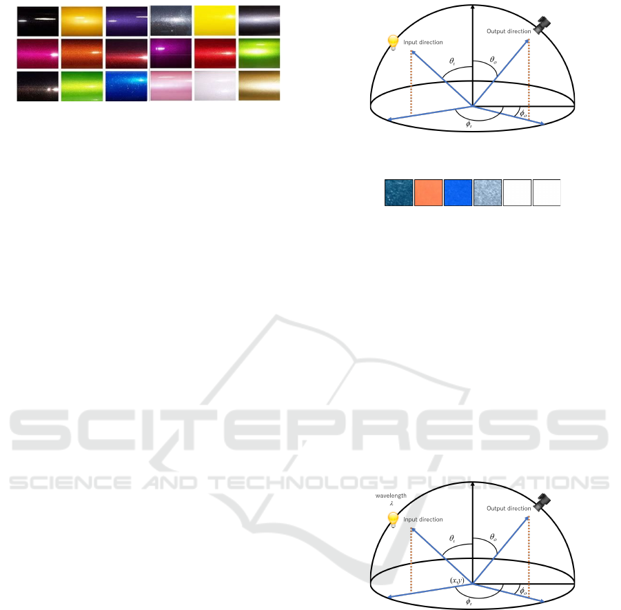
Figure 1: Example of color variation of a vehicle.
Note, the product inspection in this study is not to
detect partial abnormalities such as scratches and dirt,
but to detect overall abnormalities such as differences
in products and color errors. The proposed method
may be able to deal with partial anomalies as well, but
we will not deal with their verification in this paper.
2 REPRESENTATION OF
REFLECTANCE PROPERTIES
2.1 Bidirectional Reflectance
Distribution Function: BRDF
As described in the introduction, we focus on the re-
flectance property of the coated surface. Therefore,
we first consider the representation of the reflectance
property. In order to represent reflectance property ef-
fectively, various reflectance models have been stud-
ied and proposed(Phong, 1975; Cook and Torrance,
1981). By using theses reflectance models, we can
represent light reflectance phenomena by a few pa-
rameters. However, these models use strong assump-
tions to achieve an efficient representation, for exam-
ple, the surface of the object is rough. On the other
hand, the physics-based reflectance models, which
based on observation, utilized in recent studies do
not contain the assumption. Bidirectional Reflectance
Distribution Function (BRDF) is one of the most
representative phisics-based reflectance mode(Matt
Pharr and Greg Humphreys, 2004).
The BRDF describes distribution of a reflectance
ratio f (θ
i
, φ
i
, θ
o
, φ
o
) when a light ray from a direction
(θ
i
, φ
i
) to a direction (θ
o
, φ
o
) as shown in Fig.2. The
BRDF is 4-dimensional general function, and then
the function has many parameters. Therefore, any re-
flectance property can be represented by this BRDF.
However, long time observation is required to obtain
the BRDF accurately.
2.2 Bidirectional Texture Function:
BTF
By using the BRDF, any object surface property can
be represented. However, the BRDF cannot represent
Figure 2: Input light ray and output light ray for BRDF
representation.
Figure 3: Examples of appearance of the coated object sur-
faces.
the surface property completely since the objects’ sur-
faces consist of many materials. Figure3 shows exam-
ples of coated surfaces. As shown in this figure, the
surface coating is made up of multiple materials such
as paint, glitter, and so on. Therefore, a single BRDF
is not enough to represent surface coating.
To represent the reflectance of surface tex-
ture, the Bidirectional Texture Function(Dana et al.,
1999) is utilized. As shown in Fig.4, the BTF
f (x, y, θ
i
, φ
i
, θ
o
, φ
o
) represents reflectance property,
i.e. BRDF, on each point (x, y) by using a 6-
dimensional function. Therefore, the BTF represents
not only property on a point but also property on a
surface.
Figure 4: BTF parameters.
3 EFFECTIVE BTF
REPRESENTATION WITH
MULTISPECTRAL IMAGING
As described above, BTF can represent the reflectance
property completely when the distribution of materi-
als on the surface is constant. However, the distribu-
tion of materials, i.e. BRDF, in a texture is not nec-
essarily constant on general coatings. Therefore, in
order to appropriately represent the properties of tex-
tures, a statistical distribution model is required.
Inspection of Industrial Coatings based on Multispectral BTF
157
Besides, BTF and BRDF are represented by just
RGB color in ordinary cases. However, RGB im-
ages are not enough to represent reflectance property
since the reflectance ratio described by the models
strongly depends on the light’s wavelength. There-
fore, multispectral imaging is required to describe the
reflectance property of the surface accurately.
For these reasons, we utilize the multispectral
BTF, not taken from RGB images but from multi-
spectral images. The multispectral BTF represents
the reflective properties of the paint and coating. Fur-
thermore, we propose a method to represent the sta-
tistical properties of the multispectral BTFs using a
framework of a GAN(Goodfellow et al., 2014; Rad-
ford et al., 2015), which is one of the most representa-
tive deep neural networks. By this multispectral BTF
representation technique, we will achieve an efficient
inspection method for industrial coatings.
3.1 Simplified Multispectral BTF
Firstly, we define the multispectral BTF used in this
study. As mentioned above, a 7-dimensional func-
tion is required to represent the BTF that includes
the wavelength of light. Although this 7-dimensional
information may contain complete information for
product inspection, it would require a lot of imaging
time and complicated imaging devices to acquire all
of this information. Therefore, it is not practical to
obtain and use the 7-dimensional information com-
pletely. Therefore, we define a simplified multispec-
tral BTF for practical use.
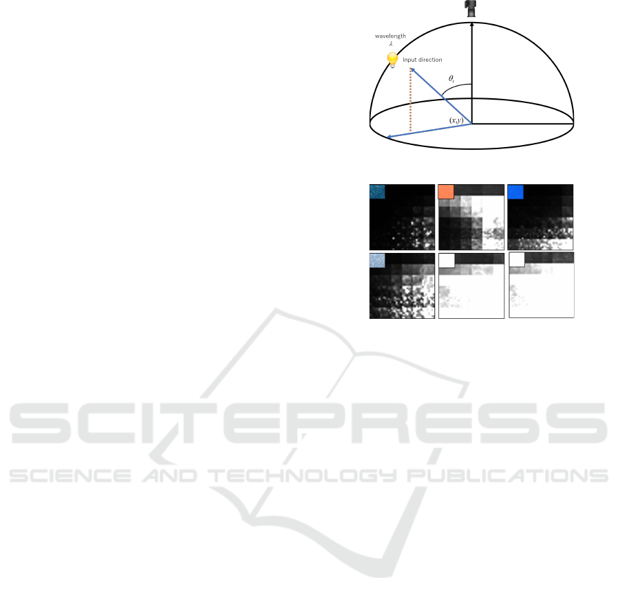
In this simplified multispectral BTF, a camera
fixed directly above the target is utilized, as shown in
Figure 5. Also, the light source is fixed in the direc-
tion of longitude φ
i
and moves only in the direction of
latitude θ
i
. The light source is equipped with several
light sources that can emit narrow-band light, and by
switching these light sources turning on and off, we
can obtain the reflection characteristics in each band.
The information in the BTF can be compressed signif-
icantly because this simplified BTF can be expressed
as a 4-dimensional function of f
t
(x, y, θ
i
, λ).
Figure 6 is an example of a simplified BTF. The
images at the upper left in each images is an image
taken by an ordinary RGB camera. This BTF image
is a list of images taken under different latitudes and
wavelengths, where the horizontal direction shows
the change of wavelength λ and the vertical direction
shows the change of latitude θ
i
of the light source. Al-
though these images include some similarities in the
RGB images, it can be seen that the different BTFs
are different features for these images as well.
Figure 5: Simplified BTF.
Figure 6: Examples of simplified BTF.
3.2 BTF Representation by GAN
Generative Adversarial Networks, or GAN, are one
of the most successful image generation techniques
in recent years in the field of deep learning. This
GAN achieves higher performance than the method
using a single network by competing the network for
image generation and the network for discriminating
the authenticity of images.Furthermore, various im-
age generation methods derived from the GAN have
been proposed, and neural network-based image gen-
eration methods have made great progress. In this pa-
per, we use this GAN mechanism and auto-encoder
technique to statistically represent the BTF.
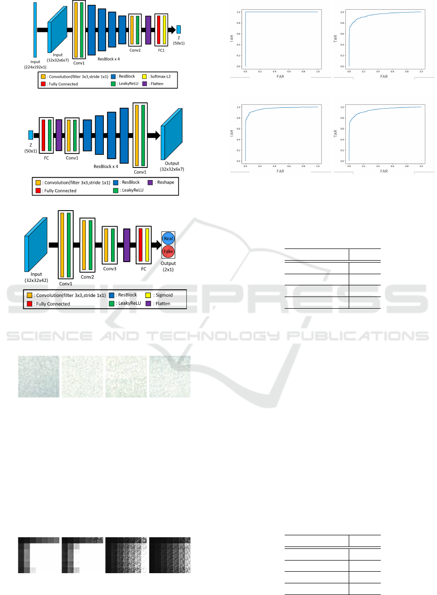
Figure 7 shows the outline of the network struc-
ture used in this study. In this network, the input BTF
image is first mapped into the latent space by an en-
coder E and then reconstructed as an image by a gen-
erator G. This structure is similar to that of a general
auto-encoder. However, when a general auto-encoder
is used for image mapping and reconstruction, the re-
constructed image tends to be smeared. Therefore, the
discriminator, which is used in GAN, is introduced in
this network to make the reconstructed image more
similar to the class of the input image.
Let E denote the encoder that maps the image X to
the latent space and G denotes the generator that re-
constructs the image from the latent space. Let D de-
note the discriminator that discriminates whether the
image is from a generator or a real image. In this case,
the optimal generator G
∗
is trained to satisfy the fol-
VISAPP 2021 - 16th International Conference on Computer Vision Theory and Applications
158

Figure 7: Network architecture for image encoding and de-
coding.
lowing.
G
∗
= argmin
G
max
D
V (G, D) (1)
V (G, D) = E[log D(X)]
+E[log(1 −D(G(E(X))))]
+E[kX − G(E(X))k] (2)
where E is the expectation value. The first and sec-
ond terms in V (G, D) are loss functions resulting from
the discriminator in GAN. The third term is the image
reconstruction error, which is similar to that used in
auto-encoder. Thus, by optimizing the discrimination
by the discriminator and the image reconstruction er-
ror simultaneously, we can reconstruct a more accu-
rate image than using the reconstruction error alone.
Thus, the latent space represents the extent of the
BTF, such as the distribution of statistical textures and
the distribution of reflectance properties.
4 ONE-CLASS CLASIFFIER
USING GAN FOR PRODUCT
INSPECTION
4.1 Distance from Latent Space in
Image Space
We consider a method for determining the input BTF
belongs to an objective (registered) class or not. This
problem is one-class identification problem using the
BTF. By the method described in 3.2, we can obtain a
latent space that can adequately represent the distribu-
tion of BTFs. When we consider the latent space as a
nonlinear subspace or a manifold in the image space,
we can compute the class identity of the input BTF by
calculating the distance between the input BTF and
the manifold. When an image is mapped and recon-
structed, some components that cannot be described
in the latent space is lost, and then the distance d
i
be-
tween the latent space and the input is computed as
follows:
d
i
= kG(E(X)) − Xk
2
(3)
If the input BTF matches the BTF represented by the
GAN, then the reconstructed and the input images are
considered similar. Therefore, by calculating the dis-
tance d
i
, the similarity between the objective class and
the input BTF can be measured.
4.2 Image Re-encoder for Classification
Using the encoders and generators described above,
we can calculate the similarity between the input im-
age and the registered image class. However, the
distance in the image space can easily change due
to the inclusion of image noise. In addition, it of-
ten happens that the distance in the image space is
not so large even if the image pairs look different
at glance. Therefore, for stable discrimination, it is
necessary to measure distances in the salient feature
space, where image features are more prominently
represented. Therefore, the reconstructed image is
mapped again into the latent space and the distance
in the latent space is used for identification.
For this purpose, we learn a new encoder E
2
to
map the reconstructed image to the latent space again.
The encoder E
2
can be trained by minimizing the
following loss so that the map E
2
(G(E(X))) of the
reconstructed image G(E(X)) is similar to the map
E(X) of the input image.
ε
1
= ||E
2
(G(E(X))) − E(X)|| (4)
By minimizing this ε
1
, the reconstructed image can
be mapped to a latent space similar to that by E. This
makes it possible to define the distance in the latent
space of the input image X as follows:
d
l
= kE
2
(G(E(X))) − E(X)k (5)
By using the distance d
l
in this latent space, we can
compute the similarity that better reflects the image
features.
4.3 Pre-training of Auto-encoder
When computing the BTF similarity using distances
in a latent space, the generalization of the latent space,
i.e., the ability to represent the BTF, has a significant
impact on the discrimination results. This is because
if the encoder consists of only images of the regis-
tered class, we do not know where the BTF far from
the registered class are mapped in the latent space.
In this case, a different class of BTFs, the distances
inside the latent space happen to be close together.
In order to solve these problems, it is important to
be able to separate different classes within the latent
space.Therefore, in this study, we pre-train this en-
coder to represent various images using a discrimina-
tion problem.
Let us consider the case when we have an image
set X
i
that belongs to class i. If X
i
is classified based
Inspection of Industrial Coatings based on Multispectral BTF
159

Figure 8: Network architecture.
on the z
i
, which is mapped to the latent space using
the encoder E, the encoder E can represent various
classes of images appropriately. Therefore, we train
E and C by connecting a new classification network C
connected to the encoder E and minimizing its output
with the following cross-entropy error ε
2
.
ε
2
= −
∑
k
t
k
C(E(X
i
)) (6)
where t
k
is a correct label that is 1 when k = i and
0 otherwise. In this way, we can improve the repre-
sentation of E by learning the Encoder E in advance
using discrimination problems.
4.4 Product Inspection Network
We summarize the network used in this study for
product coating inspection. Figure 8 summarizes the
network structure used in the similarity computation.
By using this network, it is possible to compute the
distance d
i
between the input image and the latent
space in the image space, and the distance d
l
in latent
space. Therefore, the following distances, which are
integrated from these distances, are used as indices
for product inspection.
d = (1 − w)d
i
+ wd
l
(7)
By Using this distance d, we determine whether the
input image is proper (1) or not (0) by the following
threshold processing.
δ(X) =
1 d ≤ θ
0 otherwise
(8)
5 EXPERIMENTAL RESULTS
5.1 Environment
We show several experimental results to confirm the
effectiveness of the proposed method. In these ex-
periments, we measured the BTF of actual industrial
Table 1: Specification of the experiment.
# of classes 107
image block size 32 × 32
# of wavelength 6
# of latitude 7
# of images for each class 600
products and checked whether it was possible to dis-
criminate between registered products and other prod-
ucts using the proposed one-class classifier. There are
various kinds of coatings on these products, and we
used 107 products in our experiments. We chose sev-
eral products as known products in these 107 prod-
ucts, and the encoder E was pre-trained by using
them. We also chose one product as a registered prod-
uct that we wanted to identify, and we trained a gen-
erator G and an encoder E
2
by this. Using the trained
G, E, and E
2
, we tested whether the proposed one-
class discriminator can discriminate between regis-
tered products and the unknown products. For com-
parison, experiments were conducted with several
features as well as proposed multispectral BTFs. The
features used for the comparison are ordinary BTF,
multispectral images and RGB images. The encoders
E and E
2
, and the generator G were trained by using
the features in the same way for multispectral BTF.
Note that the RGB and multispectral images were
taken under a single light source. Table 1 summarizes
the specification of the experiment in table 1. The de-
tailed network structure of the encoder, generator and
discriminator is shown in Fig.9.
5.2 Results
First, we experimented with checking whether the
proposed one-class discriminator can be used to iden-
tify similar products. In this experiment, we chose the
4 white products shown in Figure 10. As shown in this
figure, these products are very similar to each other in
the RGB image. One of these products is registered.
So, G and E
2
were trained by the registered class. The
other is used as the test class. We checked whether the
registered product and the test product could be clas-
sified. Figure 11 is an image of a product taken by
an RGB camera. Also, Figure 11 shows the results of
measuring the multispectral BTF from each product.
These images show that even though the products are
very similar in the RGB images, they have different
features in the multispectral-BTF.
Figure 12 shows ROC (Receiver Operating Char-
acteristics) curve, which is drawn from a set False
Acceptance Rate (FAR) and True Accept Rate (TAR)
with varying the threshold. This graph shows the clas-
sifier’s characteristics, and when the curve close to
VISAPP 2021 - 16th International Conference on Computer Vision Theory and Applications
160
(a) encoder
(b) generator
(c) discriminator
Figure 9: Detailed network architectures for (a)encoder,
(b)generator and (c)discriminator.
(a) (b) (c) (d)
Figure 10: Target products taken by RGB camera.
the upper left, the characteristics become better. The
worst property is when the curve is a diagonal line.
When the multispectral BTF is used, the ROC curve
is surprisingly closer to the upper left. In contrast, the
ROC curve is closer to the diagonal in the case of the
other features are used, which shows a clear inferior-
ity in performance compared to the case of multispec-
tral BTF. The area under the curve (AUC) in each case
are shown in table2, where AUC is the overall evalua-
(a) (b) (c) (d)
Figure 11: Examples of multispectral BTF for each product.
(a) multispectral BTF (b) ordinary BTF
(c) multispectral image (d) RGB image
Figure 12: ROC curves: (a) shows ROC for multispectral
BTF, (b) is for ordinary BTF, (c) is for multispectral image
and (d) is for RGB image.
Table 2: Area under curve (AUC) for each ROC curve.
features AUC
mult-BTF 1.00
ordinary BTF 0.96
mult-image 0.97
RGB image 0.94
tion of ROC, from 1 in the best case to 0.5 in the worst
case. The effectiveness of multispectral BTF can be
confirmed by the fact that better results were obtained
with multispectral BTF in table2 as well. These re-
sults confirmed the effectiveness of the multispectral
BTF in the inspection of coatings.
Next, we present the results of an exhaustive ex-
periment. In this experiment, we used half of the
107 classes for pre-training in the encoder E. We
chose a class that was not used for pre-training and
used it as the registered class. The other classes that
were not used in either of the pre-training registra-
tions were used as test classes to confirm they could
be classified into the registered class. This operation
was repeated 25 times while varying the registered
class. The ROC curves obtained in the experiments
are shown in Figure13. The AUCs for each result are
also shown in Tab.3
Table 3: Area under curve (AUC) for each ROC curve.
features AUC
mult-BTF 0.98
ordinary BTF 0.98
mult-image 0.96
RGB image 0.92
Inspection of Industrial Coatings based on Multispectral BTF
161

(a) multispectral BTF (b) ordinary BTF
(c) multispectral image (d) RGB image
Figure 13: ROC curves for (a) multispectral BTF, (b) ordi-
nary BTF, (c) RGB image and (d) multispectral image.
In these results, we can confirm that the best dis-
crimination results are obtained with the proposed
method. Thesed results indicate that the classification
performance by the proposed method is higher than
other results using the other features. These results
confirm that the multispectral BTF proposed in this
paper can adequately represent the coating character-
istics of industrial products.
6 CONCLUSION
In this study, a multispectral BTF was proposed to
represent the reflective properties of fine surfaces for
the inspection of industrial products. In addition, a
method for 1-class identification using deep learning
for product inspection using multispectral BTF is pre-
sented. Furthermore, one-class discrimination exper-
iments of actual products were conducted using the
proposed method, and it was confirmed that the mul-
tispectral BTF is effective for the inspection of coat-
ings. In future work, we plan to study not only the
identification of products but also a method for detect-
ing partial abnormalities such as scratches and dirt.
REFERENCES
Akcay, S., Atapour-Abarghouei, A., and Breckon, T. P.
(2018). Ganomaly: Semi-supervised anomaly detec-
tion via adversarial training. In Asian conference on
computer vision, pages 622–637. Springer.
Akc¸ay, S., Atapour-Abarghouei, A., and Breckon, T. P.
(2019). Skip-ganomaly: Skip connected and adversar-
ially trained encoder-decoder anomaly detection. In
2019 International Joint Conference on Neural Net-
works (IJCNN), pages 1–8. IEEE.
An, J. and Cho, S. (2015). Variational autoencoder based
anomaly detection using reconstruction probability.
Special Lecture on IE, 2(1):1–18.
Bergman, L. and Hoshen, Y. (2019). Classification-based
anomaly detection for general data. In International
Conference on Learning Representations.
Bergmann, P., L
¨
owe, S., Fauser, M., Sattlegger, D., and Ste-
ger, C. (2019). Improving unsupervised defect seg-
mentation by applying structural similarity to autoen-
coders.
Cook, R. L. and Torrance, K. E. (1981). A reflectance model
for computer graphics. SIGGRAPH Comput. Graph.,
15(3):307–316.
Dana, K. J., van Ginneken, B., Nayar, S. K., and Koen-
derink, J. J. (1999). Reflectance and texture of real-
world surfaces. ACM Trans. Graph., 18(1):1–34.
Dehaene, D., Frigo, O., Combrexelle, S., and Eline, P.
(2019). Iterative energy-based projection on a normal
data manifold for anomaly localization. In Interna-
tional Conference on Learning Representations.
DOERSCH, C. (2016). Tutorial on variational autoen-
coders. stat, 1050:13.
Goodfellow, I., Pouget-Abadie, J., Mirza, M., Xu, B.,
Warde-Farley, D., Ozair, S., Courville, A., and Ben-
gio, Y. (2014). Generative adversarial nets. In
Advances in neural information processing systems,
pages 2672–2680.
He, K., Zhang, X., Ren, S., and Sun, J. (2016). Deep resid-
ual learning for image recognition. In Proceedings of
the IEEE Conference on Computer Vision and Pattern
Recognition (CVPR).
Matt Pharr and Greg Humphreys (2004). Physically Based
Rendering: From Theory to Implementation. Morgan
Kaufmann.
Minhas, M. S. and Zelek, J. S. (2019). Anomaly detection
in images. CoRR, abs/1905.13147.
Perera, P. and Patel, V. M. (2019). Learning deep features
for one-class classification. IEEE Transactions on Im-
age Processing, 28(11):5450–5463.
Phong, B. T. (1975). Illumination for computer generated
pictures. Commun. ACM, 18(6):311–317.
Radford, A., Metz, L., and Chintala, S. (2015). Unsu-
pervised representation learning with deep convolu-
tional generative adversarial networks. arXiv preprint
arXiv:1511.06434.
Schlegl, T., Seeb
¨
ock, P., Waldstein, S. M., Schmidt-Erfurth,
U., and Langs, G. (2017). Unsupervised anomaly de-
tection with generative adversarial networks to guide
marker discovery. In International conference on in-
formation processing in medical imaging, pages 146–
157. Springer.
Zhang, J., Xie, Y., Liao, Z., Pang, G., Verjans, J., Li,
W., Sun, Z., He, J., Li, Y., Shen, C., et al. (2020).
Viral pneumonia screening on chest x-ray images
using confidence-aware anomaly detection. arXiv:
2003.12338.
VISAPP 2021 - 16th International Conference on Computer Vision Theory and Applications
162
