
Real-time Multispectral Image Processing and Registration on 3D Point
Cloud for Vineyard Analysis
Thibault Clamens, Georgios Alexakis, Rapha
¨
el Duverne, Ralph Seulin, Eric Fauvet and David Fofi
ERL VIBOT CNRS 6000, ImViA EA 7535, Universite de Bourgogne Franche Comte (UBFC), 71200, Le Creusot, France
georgios.alexakis@etu.u-bourgogne.fr
Keywords:
Agricultural Robotics, Precision Viticulture, Multispectral Imaging, Image Registration, 3D Point Cloud.
Abstract:
Nowadays, precision agriculture and precision viticulture are under strong development. In order to accom-
plish effective actions, robots require robust perception of the culture and the surrounding environment. Com-
puter vision systems have to identify plant parts (branches, stems, leaves, flowers, fruits, vegetables, etc.) and
their respective health status. Moreover, they must merge various plant information, to measure agronomic
indices, to classify them and finally to extract data to enable the agriculturist or expert to make a relevant
decision. We propose a real-time method to acquire, process and register multispectral images fused to 3D.
The sensors system, consisting of a multispectral camera and a RGB-D sensor, can be embedded on a ground
robot or other terrestrial vehicles. Experiments conducted in the vineyard field demonstrate that agronomic
analyses are allowed.
1 INTRODUCTION
Agriculture represents a challenging topic, especially
when it comes to impact production for physiological
needs. The overall production must increase its out-
put while improving food quality and being always
more respectful of the environment (OECD, 2020).
Cultivation techniques should be improved, and pre-
cision agriculture is developing itself. As the defini-
tion stated in (Precision Agriculture, 2020), precision
agriculture is a strategy that combines information to
make progress in agricultural production.
These recent practices require working as close
as possible to the plant with specific instruments and
new smart tools. Robotics and new technologies can
address some of the challenges and assist agricultural
workers. Complexity of the tasks is due to many fac-
tors. First, agricultural robots should perform outdoor
navigation and moreover in arduous fields, so they
may operate under adversarial conditions. Second,
agricultural robots must deal with growing vegeta-
tion: in a field, there may be several species of plants
or numerous different plant conditions to detect and
analyse, which makes the associated automatic pro-
cessing particularly challenging to set up.
Perception in natural outdoor environment is a
hurdle. In order to accomplish effective actions,
robots require robust perception of the culture and
the surrounding environment. Consequently, several
types of data could beneficially requiring multiple
modalities acquisition.
In this contribution, we propose a geometric and
radiometric information fusion. Radiometric infor-
mation is ended up with a multi-spectral camera and
3D point clouds are generated by a RGB-D sensor.
We present a complete computer vision pipeline em-
bedded on a mobile robot:
• Image acquisition of several modalities.
• Pre-processing and processing methods of multi-
spectral (MS) image.
• MS image registration with 3D point cloud.
The data have been acquired in the vineyard. This
multi-modal fusion approach enables further geomet-
ric and radiometric analyses. They are intended to
help solving wine-growing problems such as: the
analysis of the effectiveness of phytosanitary treat-
ments or the early detection of plant pathologies.
2 RELATED WORKS
Multi-modal data fusion remains a key principle when
addressing various sources of information to combine
different analyses on plants. Matching multi-spectral
388
Clamens, T., Alexakis, G., Duverne, R., Seulin, R., Fauvet, E. and Fofi, D.
Real-time Multispectral Image Processing and Registration on 3D Point Cloud for Vineyard Analysis.
DOI: 10.5220/0010266203880398
In Proceedings of the 16th International Joint Conference on Computer Vision, Imaging and Computer Graphics Theory and Applications (VISIGRAPP 2021) - Volume 4: VISAPP, pages
388-398
ISBN: 978-989-758-488-6
Copyright
c
2021 by SCITEPRESS – Science and Technology Publications, Lda. All rights reserved
images with 3D point cloud can be solved by several
approaches: it may be a problem similar to the regis-
tration between RGB image and multi-spectral image,
then a registration between 2D image and depth im-
age.
2.1 RGB/Multi-spectral Matching
RGB and multi-spectral images have the same modal-
ity but a different number of channels. Image regis-
tration techniques are a known problem in computer
vision (Zitova and Flusser, 2003). Two methods are
distinct: area-based and features-based methods. Cor-
ners or edges may be easily detectable and considered
as features to register images (Islam and Kabir, 2013).
Recently, multi-modal registration techniques by mu-
tual information computation are used more and more
(Nag, 2017). The hybridisation with features-based
measures increase robustness.
Some works use a Kinect
R
thanks to which depth
sensor is factory registered to the RGB camera. So,
they can register RGB images on thermal images by a
corner detection calibration to enable a multi-modal
RGB-depth-thermal segmentation (Palmero et al.,
2016).
With the development of deep learning methods,
a convolutional neural network is devised to extrinsi-
cally calibrate multi-modal sensors like a LiDAR and
a RGB camera (Schneider et al., 2017).
Capturing different data modalities makes it more
difficult to match them and finally to extract infor-
mation. Although, plant science needs multi-modal
sensors to analyse a complex environment that is veg-
etation. An extrinsic calibration between RGB and
infrared (IR) cameras is accomplished thanks to an
intensity-based method (Douarre et al., 2019).
2.2 2D/3D Data Fusion
Liu et al. (Liu et al., 2018) proposed a multi-spectral
3D visual system composed of two cameras, that reg-
ister several different spectral bands and create a 3D
corresponding point cloud. SURF algorithm is ap-
plied to detect features.
A vehicle mounted high resolution multi-spectral
3D scanner was designed (Meyers et al., 2019). A
360 degrees visual camera consisting of six CMOS
sensors, four thermal cameras and four LiDAR com-
pose this concept.
Recently, some accomplishments took advantage
of UAV by carrying light multi-spectral camera.
Then, photogrammetry software can create a 3D map
of an entire field with vegetation indices (Franzini
et al., 2019; Jurado et al., 2020; Comba et al., 2019;
Agisoft, 2020).
To work as close as possible to the plants, to carry
the sensors and the computer equipment, we do not
use a UAV but a terrestrial mobile robot. The robust-
ness of a Kinect V2 and the factory registration of
the depth image with the RGB image represent ad-
vantages to choose this sensor. Thus, the alignment
of the RGB image on the multispectral image allows
merging radiometric information on 3D.
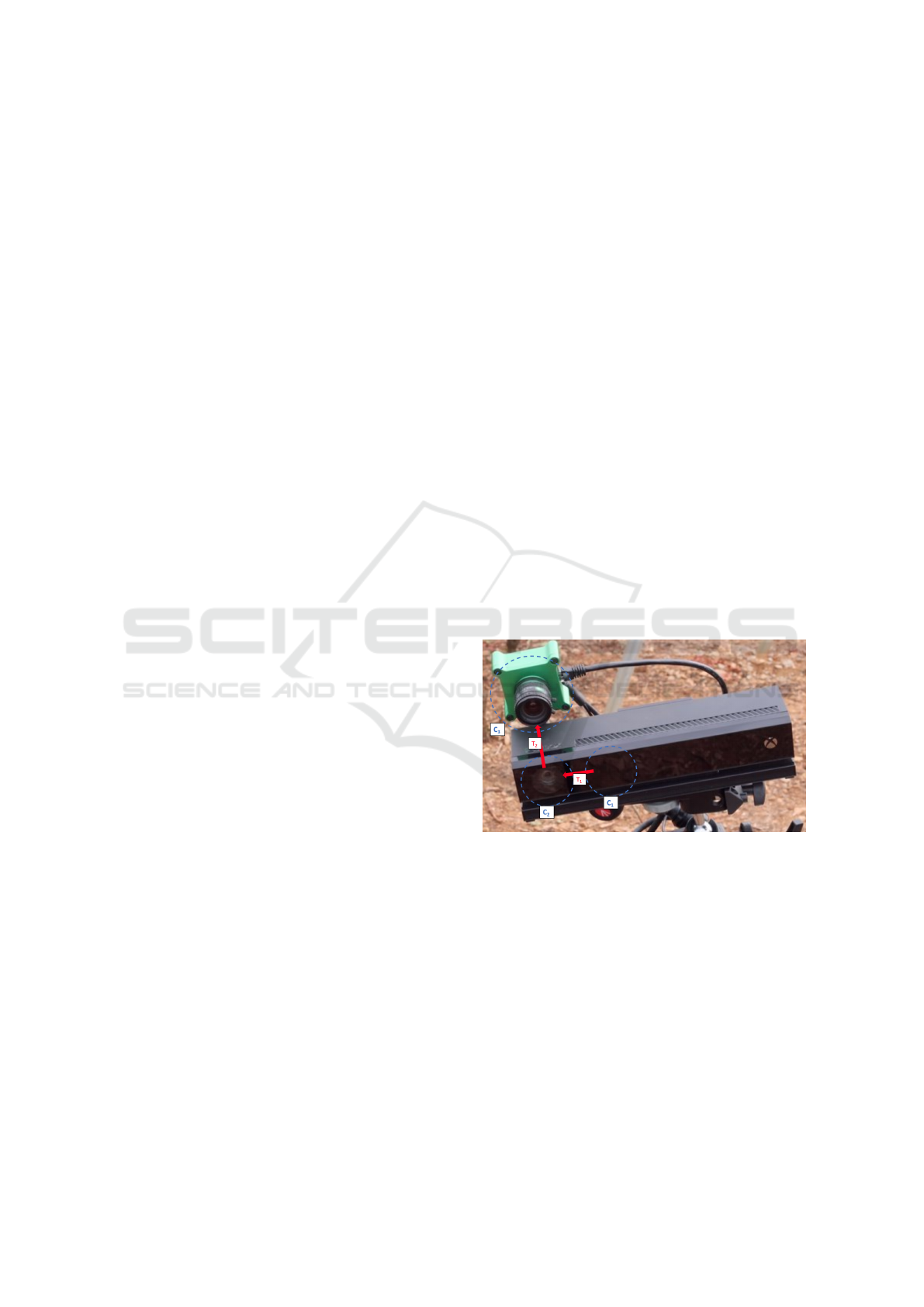
3 SETUP AND METHODS
Multi-spectral camera requires a specific procedure of
acquisition, pre-processing, intrinsic calibration and
processing before exploiting its data. Depth and RGB
images acquired by the Kinect sensor are factory reg-
istrated (represented by transformation T
1
in figure
1). Therefore, thanks to an extrinsic calibration be-
tween Kinect’s RGB camera and multi-spectral cam-
era (transformation T
2
in figure 1), the multi-spectral
image can be registered on 3D point clouds generated
by the Kinect’s depth camera. The figure 2 flowchart
is describing the complete data acquisition and pro-
cessing pipeline.
Figure 1: Multi-Sensor system consisting of a Kinect V2
(depth camera C
1
and RGB camera C
2
) and a multi-spectral
camera C
3
. Registration from depth to RGB camera frame,
and from RGB to multi-spectral camera frame are repre-
sented, respectively by T
1
and T
2
.
3.1 Setup
The main components are a CMS-V multi-spectral
camera from Silios Technologies (camera C
3
in fig-
ure 1) and a Kinect V2 sensor that is an RGB-D cam-
era from Microsoft (cameras C
1
and C
2
in figure 1).
These hardware are integrated under a ROS middle-
ware (Robot Operative System, (ROS, 2020b)).
Real-time Multispectral Image Processing and Registration on 3D Point Cloud for Vineyard Analysis
389
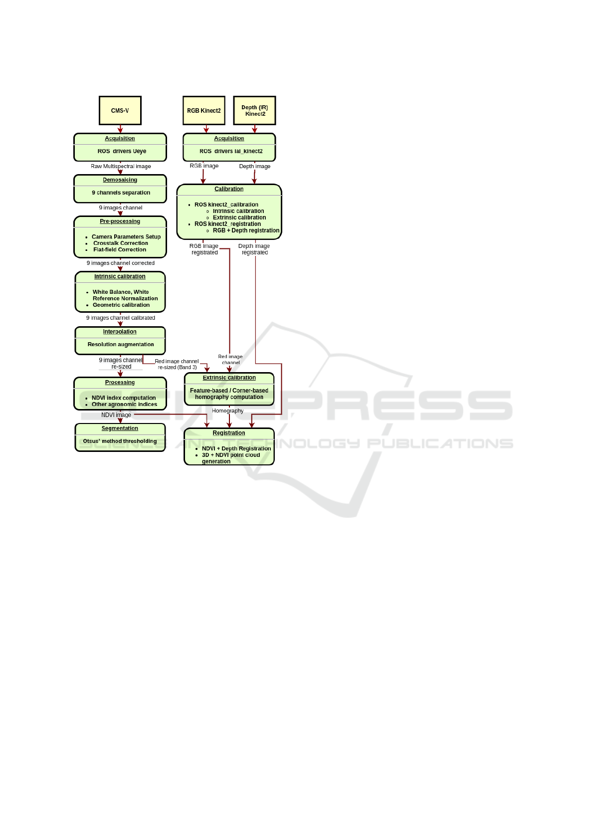
Figure 2: Complete pipeline flowchart: data captured by
multi-spectral CMS-V camera and RGB-D Kinect2 sensor.
3.1.1 Multispectral Camera
The CMS-V GigE camera is a lightweight multispec-
tral (MS) camera. Its sensor has a modified Bayer
matrix on a 1.3 megapixels CMOS sensor, made of
3x3 pixel groups called macro-pixel, resulting in 9
different channels. For our purpose, we mainly use
band 3 and band 6, corresponding to band-pass filters
centred on the wavelengths 634nm and 752nm. Espe-
cially, a raw image with resolution 1280x1024 pixels
captured by the camera is built of 9 sub-images that
consist of 8 spectral bands (8 band-pass filters) and
1 panchromatic channel (filter with spectral response
500-900nm). The resolution of every sub-image is
426x339 pixels (Silios, 2020).
3.1.2 Kinect V2
Microsoft Kinect V2 consists of a RGB camera and
an infrared (IR) projector and detector which map
depth through time of flight calculations. This RGB-
D sensor has been selected for the project due to its
low cost, high-quality images (HD), the ROS compat-
ibility, and the outdoor usage capability in difference
with Kinect V1 (Zhang, 2012).
3.2 Acquisition Process
Acquiring high quality images from each spectral
band requires an adequate adjustment of the acqui-
sition parameters as well as the necessary separation
of the multi-spectral image into 9 image channels.
3.2.1 Camera Parameters
Weather conditions are crucial for applications in
agriculture and luminosity can tremendously affect
images. So a right setting of significant camera pa-
rameters (Chouinard, 2019) must be carefully ex-
amined before any acquisition: Pixel Clock (MHz),
Frame Rate (14FPS), Aperture (F-numbers or F-
stops), Shutter Speed (Seconds), Exposure (between
6 and 18Seconds depending of luminosity).
3.2.2 Image Acquisition & Band Separation
A modern standard RGB camera is equipped with an
embedded micro-controller that performs the neces-
sary procedures after the raw image acquisition to ex-
tract an RGB image that is ready to use. Especially,
it reconstructs a full colour image from the 2x2 set of
pixels (Bayer Mosaic), known as demosaicing (Mal-
var et al., 2004). The MS camera does not include
any embedded micro-controller. Consequently, the
extraction of useful information from the raw cap-
tured image, needs more challenging extra work.
The MS sensor is constructed of a CMOS sensor
and a custom matrix filter assembled as a single unit.
The matrix filter is based on macro-pixels integrating
8 colour filters and 1 panchromatic filter, arranged in
a 3x3 matrix (figure 3). This arrangement is followed
in the whole image. The band separation takes it into
account and some pixels are discarded (Sauget et al.,
2018).
Therefore, from MS image acquisition, 9 image
channels are generated, i.e. one image for each spec-
tral band. ROS synchronise acquisitions between the
multi-spectral camera and the Kinect.
VISAPP 2021 - 16th International Conference on Computer Vision Theory and Applications
390
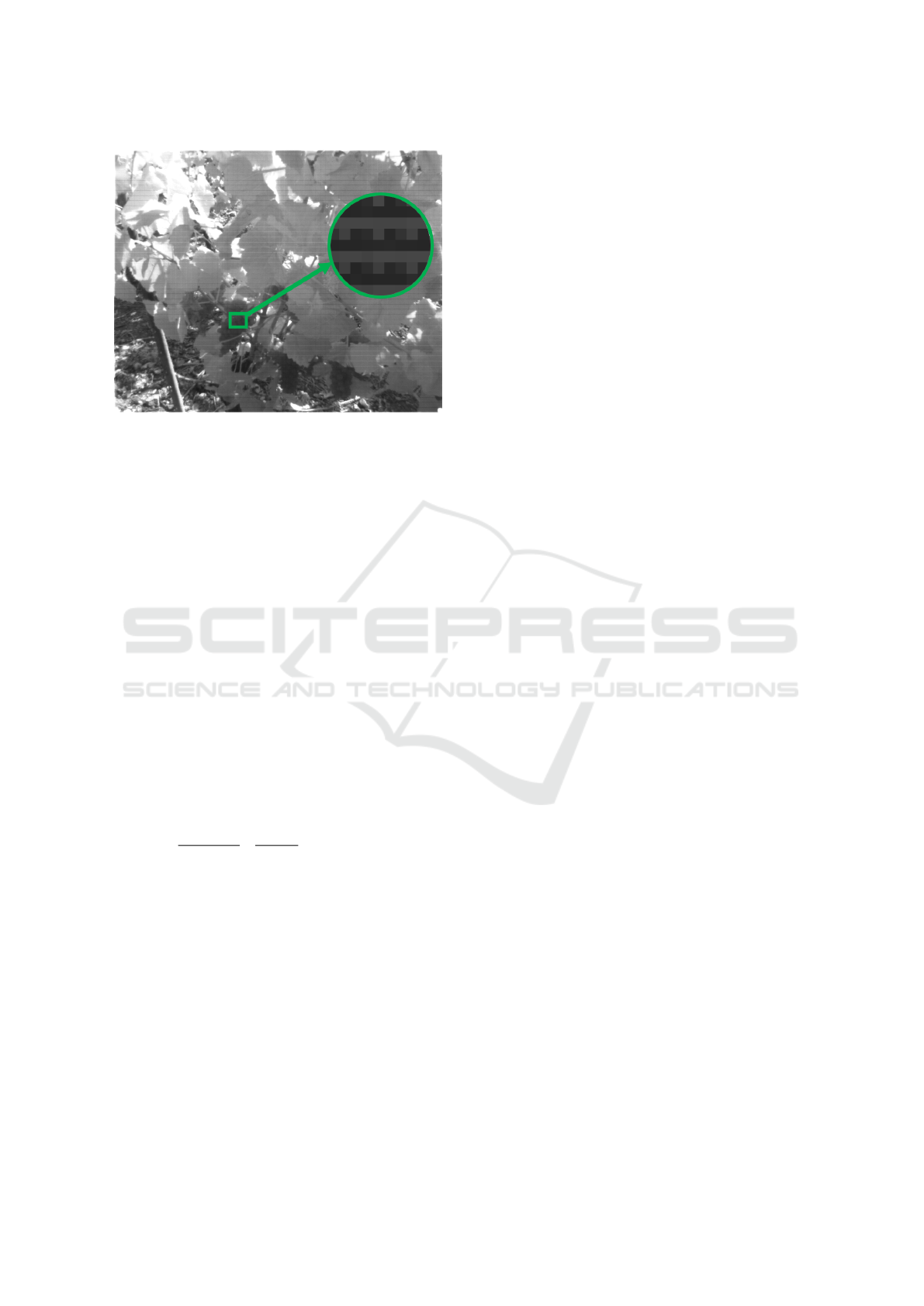
Figure 3: Raw image from multispectral camera. A zoom
is made to see the 3x3 macro-pixel organisation.
3.3 Pre-processing
When all 9 image channels are properly acquired, spe-
cific correction functions can be applied to denoise or
improve image quality.
3.3.1 Flat-field Correction
Flat-field correction is used to improve image unifor-
mity by removing or minimising unwanted artefacts
regardless of exposure. Especially, this method cor-
rects pixels of the acquired raw image in such a way
that when a uniform background is captured by the
acquisition system, the resulting output image is uni-
form (Kokka et al., 2019; Kask et al., 2016; Hagen,
2014; Seibert et al., 1998).
Because the CMS-V is not equipped with an em-
bedded micro-controller, this correction is performed
by the developed software, using this following equa-
tion:
P
i, j
=
R
i, j
− D
i, j
F
i, j
− D
i, j
∗
1
(m ∗ n)
∗
m−1
∑
x=0
n−1
∑
y=0
(F
x,y
− D
x,y
).
(1)
• P: Image after the flat-field correction process.
• R: Raw image captured by the MS camera.
• D: Dark-field image that must be acquired once
(Intensity range from 10% to 90%).
• F: Flat-field image that should be acquired once
(Image pixel values must not be 0).
• m, n: Number or rows/columns.
3.3.2 Crosstalk Correction
One of the problems that affect camera sensors is
crosstalk between the pixels. This is an effect
whereby a pixel signal is affected by the neighbor
pixels signal, that means interference between pix-
els. Therefore, the final response of a pixel does not
only depend on its sensed light, but also on its neigh-
bouring pixels and even much the closest neighbours
(Sauget et al., 2018; Getman et al., 2007; Andriani
and Brendel, 2013; Iwasaki and Tonooka, 2005; Li
et al., 2002).
The CMS-V is equipped with a MS matrix filter
on the top of a standard monochrome sensor, which
induces a higher level of crosstalk. The CMS-V man-
ufacturer provides the crosstalk coefficients, which
have been estimated for each camera and are used
in the following equation to remove or minimise this
phenomenon (Silios, 2020).
Prec
i
=
8
∑
j=0
CC
i, j
∗ P
j
. (2)
• P
j
: Response of a pixel filtered with the real filter
j, 0 ≤ j ≤ 8.
• Prec
i
: Response of a “virtual pixel” filtered with
the reconstructed filter i, 0 ≤ i ≤ 8.
• CC
i, j
: Crosstalk correction coefficients.
These flat-field and crosstalk corrections improve the
quality of the image channels and are necessary for
multi-spectral processing.
3.4 Intrinsic Calibration
The MS camera needs to be calibrated before employ-
ing these images for Kinect registration. A radiomet-
ric and geometric calibration are operated.
3.4.1 Radiometric Calibration
In image processing, colour balance is the adjustment
of color intensities in an RGB image. The aim is the
right representation of colours. Furthermore, colour
balance is referred as gray balance, neutral balance,
or white balance (Limare et al., 2011).
Especially, for the MS camera, the output of white
reference is 9 normalisation coefficients. The equa-
tion used is similar to the one used for RGB camera,
but with more channels.
A MacBeth ColorChecker is placed in the cam-
era’s field of view. The white square is chosen as
white reference for each channel image. Then, the
normalisation is performed between obtained and de-
sired pixel values to compute each white balance co-
efficient.
Real-time Multispectral Image Processing and Registration on 3D Point Cloud for Vineyard Analysis
391

3.4.2 Geometric Calibration
The geometric calibration of a camera is the estima-
tion of some lens and sensor parameters. They are
divided into three different categories, which include
intrinsic, extrinsic, and distortion coefficients.
The intrinsic parameters include the focal length,
the optical centre, and the skew coefficient. The ori-
gin of the camera coordinate system is its optical cen-
tre and its x-axis and y-axis define the image plane.
The distortion is divided into two parts. The ra-
dial distortion occurs when light rays bend more near
the edges of a lens than they do at its optical centre.
The tangential distortion occurs when the optical cen-
tres of the lens elements are not strictly collinear and
generally when the lens and the image plane are not
parallel. These affects appear due to imperfections
in lens design and camera assembly (Ly et al., 2014;
Staranowicz et al., 2013).
To estimate the camera parameters, 3D world
points are needed with their corresponding in 2D im-
age points (Wiedemeyer, 2015; Salvi et al., 1998).
The calibration process uses the points in an itera-
tive method in order to reduce the difference between
the 2D projection and the modelled one. These corre-
spondences can be acquired by using multiple images
of a calibration pattern.
This calibration for conventional monocular cam-
eras (ROS, 2020a) is implemented and applied di-
rectly to the multi-spectral image.
Kinect calibration functionalities are provided by
package iai kinect2 (Wiedemeyer, 2015). This makes
it possible to intrinsically calibrate the RGB camera
and the depth camera, and then to extrinsically cali-
brate this two-sensor system.
The radiometric and geometric calibration rectify
the multispectral image and allow the extrinsic cali-
bration with the Kinect.
3.5 Extrinsic Calibration
The depth image of the Kinect’s depth camera is reg-
istered to the RGB image frame thanks to the Kinect
extrinsic calibration. These two images are aligned,
so a 3D RGB point cloud can be created. The aim of
this extrinsic calibration is to find the registration be-
tween MS camera and RGB camera. This enables the
alignment of the depth image onto the MS image and
subsequently creating a 3D point cloud enriched with
MS data. This registration is mainly achieved by ap-
proximating the displacement matrix between the two
camera frames. We employ two approaches to calcu-
late the homography transformation between the two
images: features-based and corner-based.
3.5.1 Homography
In this project, homography is one of the main tools
for image registration. The homography relates the
transformation between two planes. Camera rotation
and translation between two images can be computed
from it. When the homography is applied to every
pixel of the Kinect’s images, new ones are warped
versions of original images (Bensoukehal, 2015) and
aligned with MS camera frame. The homography ma-
trix is a 3x3 matrix with 8 degrees of freedom (DoF).
H
x
y
1
=
h
11
h
12
h
13
h
21
h
22
h
23
h
31
h
32
h
33
x
y
1
= s
x
0
y
0
1
, (3)
with
h
33
= 1 or
∑
m,n
h
2
mn
= 1, (4)
with h the member of the homography matrix indexed
with m and n respectively, the row and the column
of the matrix. Parameters are computed by methods
detailed hereafter.
3.5.2 Image Registration
Image registration is a process in which different
types of data are projected into one common coor-
dinate space. Particularly for this approach, differ-
ent modalities have to be registered (Crombez et al.,
2018): images from the MS camera and from the
RGB-D camera.
Generally, image registration is divided into two
main categories. Intensity-based image registration
methods measure similarities in images via correla-
tion metrics of intensity patterns. Feature-based reg-
istration methods use features like edges, corners,
points, lines and contours of the images. The pro-
cedure to succeed feature-based image registration is
feature detection, feature point description, and fea-
ture points matching (Palmero et al., 2016; Douarre
et al., 2019; de Aguiar, 2015; Islam and Kabir, 2013).
Feature/Corner-based Image Registration.
Feature-based and corner-based registration ap-
proaches are implemented to register images from the
RGB-D camera with MS images. Many challenges
are faced in both approaches due to different image
resolution, different fields of view, but also the
multiple spectral bands captured, etc.
The Band 3 (λc: 634nm, FWHM: 30nm, QE
max: 20%) of the MS camera and the Red Band of
the Kinect V2 RGB image sensor have been selected
for registration. The raw image of the MS camera
contains 9 pixels for every real-world corresponding
VISAPP 2021 - 16th International Conference on Computer Vision Theory and Applications
392

pixel, so it does not have precise results for the reg-
istration process. The process steps are presented be-
low (sub-items differentiate feature-based and corner-
based methods):
• Image acquisition from both modalities (Band 3
from MS camera, Red Channel from the Kinect
sensor).
– Feature extraction from both modalities using
ORB (Oriented FAST and Rotated BRIEF) fea-
ture detector (up to 1000 unique features for
each modality).
– Corner detection of a printed chessboard by
both modalities the same time.
– Feature matching between the images of the
different modalities (more than 40 to be suc-
cessful).
– Corner matching between the images of both
modalities.
• Homography matrix computation and saving.
• Homography application to the RGB and depth
image of the Kinect sensor.
These two registration approaches compute the ho-
mography matrix (equation (3)) that describes the
transformation between the RGB camera related to
the multi-spectral one. However, practical use and re-
sults of each method are slightly different. Feature-
based registration has the advantage that no calibra-
tion chessboard or other human intervention is re-
quired. Thus, this registration could be done automat-
ically. Corner-based registration need a human inter-
vention to hold or place a chessboard in the camera
field of view, and results are better. So, each method
has benefits to be implemented, but we opt for corner-
based due to its precision. Therefore, it is possible to
visualise 3D point cloud enriched by multi-spectral
data.
3.6 Processing
Several processes can be performed adequately from
the calibrated multi-spectral image. We present a veg-
etation segmentation using an agronomic index.
3.6.1 NDVI Index
NDVI (Normalised Differential Vegetation Index) can
describe the vegetation density, allowing researchers
to evaluate vegetation, growth, and productivity. Es-
pecially, NDVI is the contrast between the red channel
(Red) and the near-infrared channel (NIR) (Zuzulova
and Vido, 2018; Panda et al., 2010).
A healthy plant will absorb blue and red light and
reflect green light, which is why they appear green
to our eyes. Plants also reflect Near-Infrared (NIR)
light, which is invisible to the human eye, also is ac-
tively unused for photosynthesis process. The health-
ier the plant, the more NIR light is reflected. When
a plant becomes dehydrated or stressed, the spongy
layer of the plant collapses, and its leaves reflect less
NIR light, yet they still reflect the equivalent amount
of light in the visible range (Motohka et al., 2010).
The most significant application of NDVI value is in
the detection of the stressed crop because it can be de-
tected sooner in near-infrared (NIR) than in the visual
spectrum. NDVI can be computed as:
NDV I =
NIR − RED
NIR + RED
. (5)
3.6.2 Segmentation
From the NDVI index, thresholding can succeed seg-
mentation of the trunk, the leaves, but also the unnec-
essary parts such as the sky, the soil or even the metal
wires of a vineyard row. Thanks to the NDVI index,
the vegetation can be separated from the other materi-
als. Otsus’s method (Otsu, 1979) is applied for back-
ground subtraction, as an automatic image threshold-
ing method, then erosion and dilation to succeed the
best result.
Indices calculated from the MS data allow agro-
nomic analysis of the vines to be carried out. In ad-
dition, treatments on the basis of 3D data can provide
a geometric analysis of the vines. The registration of
the 3D data with the MS images can combine these
two types of analysis.
4 EXPERIMENTAL RESULTS
Functions presented above were tested separately in
the laboratory and outdoor conditions. Then, they
were integrated in a real-time system to be used on-
the-go in the vineyard.
4.1 Experiments
Before launching the acquisitions in the field, a hard-
ware and parameters’ software adjustment process
have to be followed. For practical use, sensors are set
on a ground robot which is able to navigate by teleop-
eration between rows of the vineyard. This Summit
XL robot (Robotnik, 2020) is a four-wheel electric
drive controlled by an embedded computer running
on ROS (Robot Operating System).
Real-time Multispectral Image Processing and Registration on 3D Point Cloud for Vineyard Analysis
393
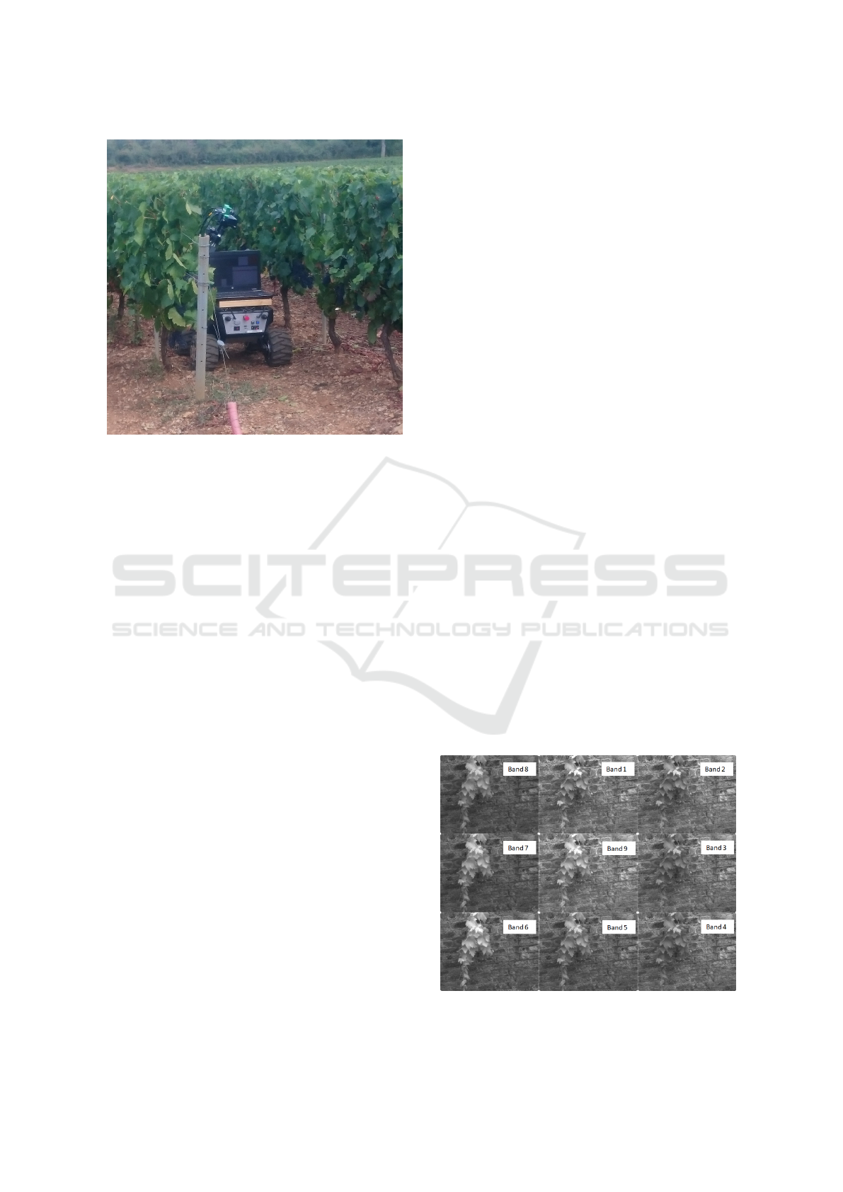
Figure 4: Summit XL robot instrumented with the multi-
sensor system.
The MS camera and the Kinect V2 are positioned and
oriented in such a way that vine boletus, branches,
leaves and grapevines are inclusive of the sensors’
field of view (figure 4). MS camera optic must be cor-
rectly adjusted before launching the acquisition. First,
the focus is modulated in function of distance to the
vineyard’s plants. Then, the optic aperture is adjusted
regarding the exterior luminosity. These two param-
eters are manually set up and can’t be adjusted af-
ter calibration. They have a significant impact on the
acquisition quality, therefore it is crucial to set them
properly.
Afterwards, other camera parameters (subsection
3.2.1) can be adapted and particularly exposure time
due to variations of luminosity conditions for avoid-
ing saturation values in some parts of images. Robot
movement speed may provoke blurred images. So in
order to test correctly all processes of MS processing
and registration with 3D, the robot speed is set to 1.22
km/h.
The calibration processes of subsection 3.4 are ex-
ecuted before acquisitions. A MacBeth ColorChecker
is used to calibrate the white balance of the MS cam-
era. The white square is manually selected for white
reference. For the geometric and extrinsic calibration,
a chessboard pattern is also placed in the field of view
of cameras.
When calibration is done, pre-processing and pro-
cessing functions can be activated. The two sensors
are synchronized, and a group of images mainly com-
posed of a MS image, a RGB image and a depth im-
age are saved with a rate of 10 frames per second.
Calibration matrices are saved during the preparation
process, so we can register images offline to reduce
the quantity of online computation and to augment the
battery time.
All functions and methods are imple-
mented on ROS and the code is available at:
https://github.com/georgealexakis/multispectral
processing.
Acquisition campaigns in real conditions were
carried out during summer 2020 in the same vineyard
field before and after harvesting of grapevines.
4.2 Results
The processes for acquisition, pre-processing, regis-
tration and processing were tested in specific experi-
mental conditions. When these are validated, experi-
ments are conducted in vineyard conditions.
The correct separation of bands in figure 5 is
verified by using of a monochromator. This instru-
ment projects the selected wavelength to the specific
nanometre range. This allowed the characterisation of
the 9 band-pass filters that makes up the customised
Bayer matrix of the multi-spectral camera.
For the efficiency demonstration of pre-processing
and processing functions, an experiment was exe-
cuted outdoors. A branch of vineyard was placed in
front of a wall. After the calculation of NDVI index,
the NDVI image of a vineyard’s branch is shown in
figure 7. The associated RGB image from the Kinect
V2 is figure 6. Figure 8 is the NDVI image with a
color-map for the different values of NDVI index. In-
deed, NDVI gives a value between -1 and 1. The
color-map is applied for each value above 0. This cus-
tom color-map in figure 10 permits to visualise levels
of NDVI index. More the color is dark green, more
vigorous is the vegetation. Figure 9 represents the
same NDVI image, however this time, the crosstalk
Figure 5: 9 channels images demosaicing from the raw
multi-spectral image.
VISAPP 2021 - 16th International Conference on Computer Vision Theory and Applications
394
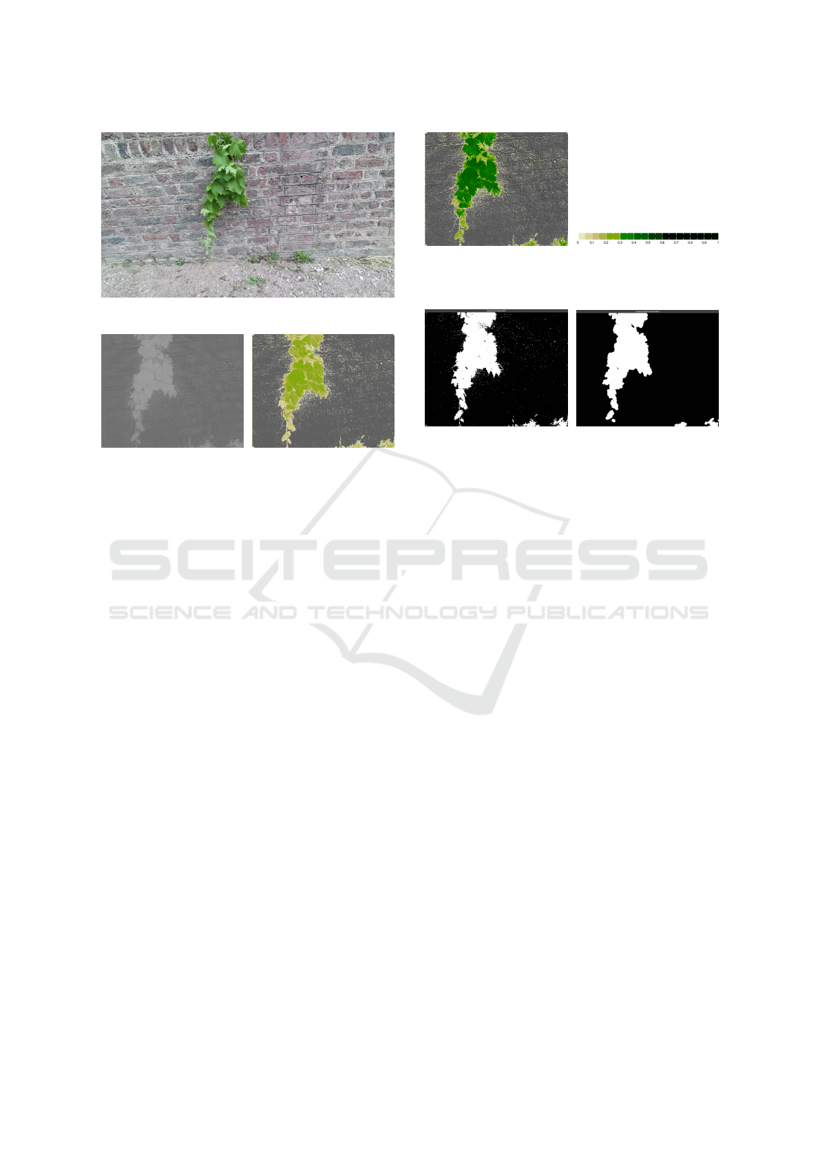
Figure 6: RGB image from Kinect V2 of a vineyard branch.
Figure 7: NDVI 8bit im-
age, after normalisation to 0
- 255.
Figure 8: NDVI colored
image, using custom color-
map.
correction function has enabled. NDVI is one of the
several indices that can be calculated from the multi-
spectral image. Thanks to this index, vegetation can
be easily segmented with Otsu’s method (figure 11
and figure 12).
Each acquisition campaign in vineyard allowed to
create a dataset of more than eight thousand pack-
ets consisting of a RGB image, a depth image, a
MS image, a NDVI image and a NDVI coloured im-
age. Other processing functions and registration can
be performed online or offline. For reasons of data
storage and battery limitations, we decided to process
data in laboratory. Here, we present a result of reg-
istration. During the preparation procedure, intrinsic
and extrinsic calibration matrices are saved. The orig-
inal RGB image of the Kinect V2 is shown in figure
13. The associated NDVI image with color-map is ex-
posed figure 15. The registration function is applied
to RGB image which is then cropped and aligned to
the MS camera frame (figure 14). Because the depth
image is already registered to the RGB image, we are
also able to compute a 3D point cloud enriched with
NDVI index. Results are presented in figure 16.
4.3 Evaluation
The combination of a MS camera with a Kinect V2
is not common. Despite the infrared light emission
by the depth sensor of the Kinect V2, only the band
8 of the MS camera is mainly affected during low lu-
Figure 9: NDVI colored
image with crosstalk pre-
processing function.
Figure 10: Custom color-
map used for NDVI colored
images.
Figure 11: Background
subtraction by using Otsu’s
method.
Figure 12: Background sub-
traction after erosion and di-
lation.
minosity conditions. Otherwise, these perturbations
can be largely neglected for other bands. A character-
isation of the Kinect’s Infrared light emission should
correct the noise caused on band 8.
The results obtained, show that the NDVI allows
an acceptable segmentation of the vegetation. How-
ever, in the field, we faced some saturation problems
when a high light intensity affects part of the foliage,
while another part may be completely shaded. This
can be corrected by a more appropriate adjustment of
the optics’ aperture and the exposure time. Upcoming
work will use 3D information to improve segmenta-
tion. Despite windy conditions during some acquisi-
tion campaigns, this did not affect the results, which
demonstrate the relative robustness of the system.
Image registration was the most essential tech-
nique that used during this project. This process can
be performed one time after the alignment of both
sensors. Due to the same characteristics, the band
3 (λc: 634nm, FWHM: 30nm, QE max: 20%) of
the MS camera and the Red channel of the RGB im-
age of the Kinect sensor have been chosen, resulting
in the most precise result. The initial image regis-
tration technique developed was feature-based image
registration, in which feature matches are detected
and lastly the registration is performed. Therefore,
matches were not correct any times and due to this
problem, corner-based image registration was devel-
oped with the specific corners of a chessboard (same
for camera calibration). Although both techniques
have very good results under laboratory conditions.
The main challenges that were faced during the exper-
Real-time Multispectral Image Processing and Registration on 3D Point Cloud for Vineyard Analysis
395
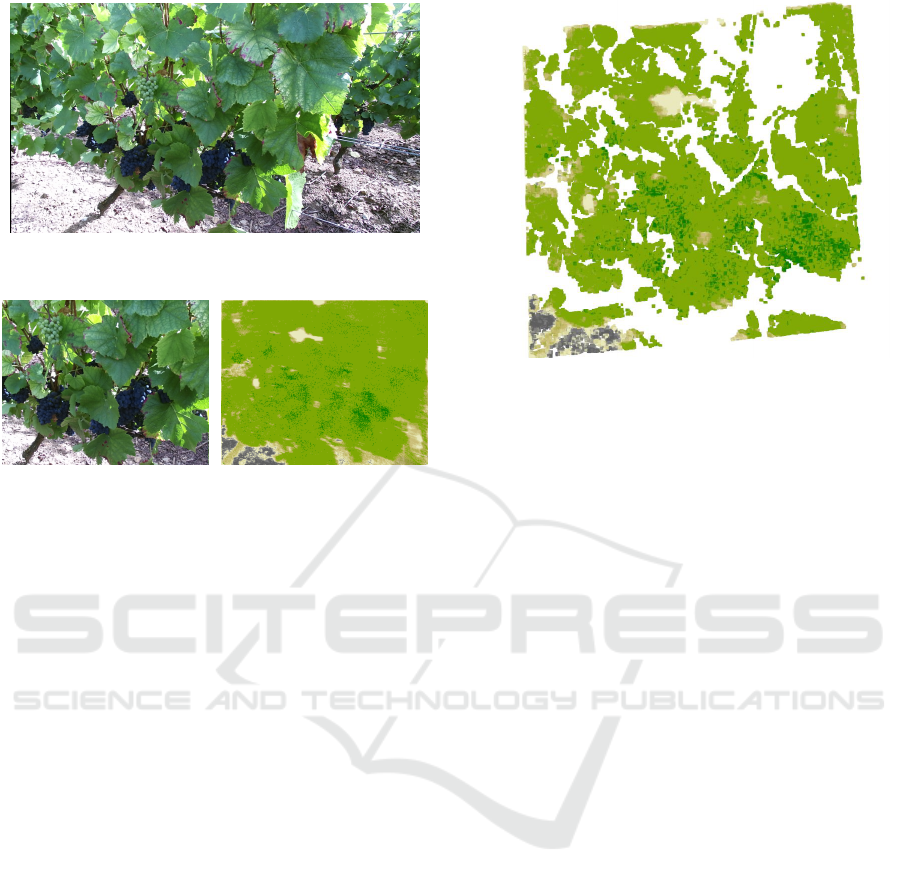
Figure 13: Original RGB image from the Kinect V2 ac-
quired in the vineyard field.
Figure 14: Registered RGB
image from the Kinect V2.
Figure 15: NDVI index of
vineyard.
iments were the cameras’ position, the different field
of view of both cameras, but also the different speci-
fications of the cameras, such as resolution, different
lenses, etc.
As an evaluation method for the image registration
approaches, the mean difference between the images
(Band 3 of the MS camera and registered Red channel
of the Kinect sensor) has been used. The image regis-
tration algorithm tries finding the homography matrix
with the minimum mean difference between images.
Generally, with this method, a comparison between
the pixels of the images is done, resulting in most pre-
cise output.
5 CONCLUSION
In this paper, we propose a whole method of multi-
spectral image acquisition, pre-processing, process-
ing, registration on 3D point cloud, working in a real-
time system, and its application to a complex environ-
ment that is vineyard.
We use a multi-spectral camera and a Kinect V2
consisting of an RGB camera and a depth camera.
These sensors are mounted on a terrestrial mobile
robot for experimentation in wine-growing sites. Sev-
eral trials were carried out during the summer of
2020 on the same vineyard, before and after the har-
vest. The code is available in open sources, and the
database produced for the vines will be available as
soon as a full acquisition season can be made.
Figure 16: NDVI index mapped on 3D point cloud.
The combination of MS, RGB and depth images gen-
erates a multi-modal data fusion, which allows to ex-
tract several types of information from the environ-
ment. The integration of various physical measure-
ments of the vine will generate its more complete
and efficient analysis. The viticulturist will be expe-
rienced to make better decisions. So, perception for
precision viticulture and agricultural robotics is im-
proved. Moreover, due to the multi-sensor system is
adaptable to diverse kinds of land carriers, following
agronomic analyses can be developed not exclusively
for viticulture, but also for various crops.
ACKNOWLEDGEMENTS
This work is funded by a grant from the French Min-
istry of Higher Education and Research. Experiments
on wine-growing sites were conducted on the Ch
ˆ
ateau
Miraudet domain (Franc¸ois Budin, Domaine Ch
ˆ
ateau
Miraudet, 71490 Dracy-L
`
es-Couches, France).
REFERENCES
Agisoft (2020). Agisoft photoscan. online:https://www.
agisoft.com/features/professional-edition/.
Andriani, S. and Brendel, H. (2013). Crosstalk correc-
tion technique for single sensor camera provided with
bayer color filter array. In 2013 IEEE International
Conference on Image Processing, pages 2252–2255.
IEEE.
Bensoukehal, A. (2015). Perspective rectification using ho-
mography planar: Plane measuring.
Chouinard, J. (2019). The fundamentals of camera and im-
age sensor technology. Baumer, Southington CT.
VISAPP 2021 - 16th International Conference on Computer Vision Theory and Applications
396

Comba, L., Biglia, A., Aimonino, D. R., Barge, P., Tortia,
C., and Gay, P. (2019). 2d and 3d data fusion for crop
monitoring in precision agriculture. In 2019 IEEE
International Workshop on Metrology for Agriculture
and Forestry (MetroAgriFor), pages 62–67. IEEE.
Crombez, N., Seulin, R., Morel, O., Fofi, D., and De-
monceaux, C. (2018). Multimodal 2d image to 3d
model registration via a mutual alignment of sparse
and dense visual features. In 2018 IEEE Inter-
national Conference on Robotics and Automation
(ICRA), pages 6316–6322. IEEE.
de Aguiar, M. A. P. F. (2015). 3d reconstruction from mul-
tiple rgb-d images with different perspectives.
Douarre, C., Crispim-Junior, C., Gelibert, A., Rousseau, D.,
and Tougne, L. (2019). A strategy for multimodal
canopy images registration. In 7th International Work-
shop on Image Analysis Methods in the Plant Sci-
ences.
Franzini, M., Ronchetti, G., Sona, G., and Casella, V.
(2019). Geometric and radiometric consistency of par-
rot sequoia multispectral imagery for precision agri-
culture applications. Applied Sciences, 9(24):5314.
Getman, A., Uvarov, T., Han, Y., Kim, B., Ahn, J., and Lee,
Y. (2007). Crosstalk, color tint and shading correction
for small pixel size image sensor. In International Im-
age Sensor Workshop, pages 166–169.
Hagen, N. (2014). Flatfield correction errors due to spectral
mismatching. Optical Engineering, 53(12):123107.
Islam, M. B. and Kabir, M. M. J. (2013). A new feature-
based image registration algorithm. Computer Tech-
nology and Application, 4(2).
Iwasaki, A. and Tonooka, H. (2005). Validation of a
crosstalk correction algorithm for aster/swir. IEEE
transactions on Geoscience and Remote Sensing,
43(12):2747–2751.
Jurado, J. M., Ortega, L., Cubillas, J. J., and Feito, F.
(2020). Multispectral mapping on 3d models and
multi-temporal monitoring for individual characteri-
zation of olive trees. Remote Sensing, 12(7):1106.
Kask, P., Palo, K., Hinnah, C., and Pommerencke, T.
(2016). Flat field correction for high-throughput imag-
ing of fluorescent samples. Journal of microscopy,
263(3):328–340.
Kokka, A., Pulli, T., Honkavaara, E., Markelin, L., K
¨
arh
¨
a,
P., and Ikonen, E. (2019). Flat-field calibration
method for hyperspectral frame cameras. Metrologia,
56(5):055001.
Li, W., Ogunbona, P., Shi, Y., and Kharitonenko, I. (2002).
Cmos sensor cross-talk compensation for digital cam-
eras. IEEE Transactions on Consumer Electronics,
48(2):292–297.
Limare, N., Lisani, J.-L., Morel, J.-M., Petro, A.-B., and
Sbert, C. (2011). Simplest color balance. Image Pro-
cessing On Line, 1.
Liu, H., Lee, S.-H., and Chahl, J. S. (2018). Registration of
multispectral 3d points for plant inspection. Precision
Agriculture, 19(3):513–536.
Ly, D. S., Demonceaux, C., Vasseur, P., and P
´
egard, C.
(2014). Extrinsic calibration of heterogeneous cam-
eras by line images. Machine vision and applications,
25(6):1601–1614.
Malvar, H. S., He, L.-w., and Cutler, R. (2004). High-
quality linear interpolation for demosaicing of bayer-
patterned color images. In 2004 IEEE International
Conference on Acoustics, Speech, and Signal Process-
ing, volume 3, pages iii–485. IEEE.
Meyers, G., Zhu, C., Mayfield, M., Tingley, D. D., Will-
mott, J., and Coca, D. (2019). Designing a vehi-
cle mounted high resolution multi-spectral 3d scanner:
Concept design. In Proceedings of the 2nd Workshop
on Data Acquisition To Analysis, pages 16–21.
Motohka, T., Nasahara, K. N., Oguma, H., and Tsuchida,
S. (2010). Applicability of green-red vegetation index
for remote sensing of vegetation phenology. Remote
Sensing, 2(10):2369–2387.
Nag, S. (2017). Image registration techniques: a survey.
arXiv preprint arXiv:1712.07540.
OECD (2020). Agriculture and the environ-
ment. https://www.oecd.org/agriculture/topics/
agriculture-and-the-environment.
Otsu, N. (1979). A threshold selection method from gray-
level histograms. IEEE transactions on systems, man,
and cybernetics, 9(1):62–66.
Palmero, C., Clap
´
es, A., Bahnsen, C., Møgelmose, A.,
Moeslund, T. B., and Escalera, S. (2016). Multi-modal
rgb-depth-thermal human body segmentation. Inter-
national Journal of Computer Vision, 118(2):217–
239.
Panda, S. S., Ames, D. P., and Panigrahi, S. (2010). Appli-
cation of vegetation indices for agricultural crop yield
prediction using neural network techniques. Remote
Sensing, 2(3):673–696.
Precision Agriculture, I. S. (2020). Precision ag defini-
tion - language modal. https://www.ispag.org/about/
definition.
Robotnik (2020). summit-xl. https://www.robotnik.eu/
mobile-robots/summit-xl.
ROS (2020a). camera calibration. http://wiki.ros.org/
camera calibration.
ROS (2020b). Robot operating system. https://www.ros.
org.
Salvi, J. et al. (1998). An approach to coded structured light
to obtain three dimensional information. Universitat
de Girona.
Sauget, V., Hubert, M., Faiola, A., and Tisserand, S. (2018).
Application note for cms camera and cms sensor
users: post-processing method for crosstalk reduction
in multispectral data and images. white paper, Silios
Technologies.
Schneider, N., Piewak, F., Stiller, C., and Franke, U. (2017).
Regnet: Multimodal sensor registration using deep
neural networks. In 2017 IEEE intelligent vehicles
symposium (IV), pages 1803–1810. IEEE.
Seibert, J. A., Boone, J. M., and Lindfors, K. K. (1998).
Flat-field correction technique for digital detectors. In
Medical Imaging 1998: Physics of Medical Imaging,
volume 3336, pages 348–354. International Society
for Optics and Photonics.
Silios (2020). Multispectral cameras cms series. https://
www.silios.com/cms-series.
Staranowicz, A., Brown, G. R., Morbidi, F., and Mariottini,
G. L. (2013). Easy-to-use and accurate calibration of
Real-time Multispectral Image Processing and Registration on 3D Point Cloud for Vineyard Analysis
397

rgb-d cameras from spheres. In Pacific-Rim Sympo-
sium on Image and Video Technology, pages 265–278.
Springer.
Wiedemeyer, T. (2014 – 2015). Iai kinect2. https://github.
com/code-iai/iai kinect2.
Zhang, Z. (2012). Microsoft kinect sensor and its effect.
IEEE MultiMedia, 19:4–12.
Zitova, B. and Flusser, J. (2003). Image registration
methods: a survey. Image and vision computing,
21(11):977–1000.
Zuzulova, V. and Vido, J. (2018). Normalized difference
vegetation index as a tool for the evaluation of agri-
cultural drought. Ecocycles, 4(1):83–87.
VISAPP 2021 - 16th International Conference on Computer Vision Theory and Applications
398
