
Integrating Kahn Process Networks as a Model of Computation in an
Extendable Model-based Design Framework
Omair Rafique and Klaus Schneider
Department of Computer Science, University of Kaiserslautern, Kaiserslautern, Germany
Keywords:
Model-based Synthesis, Kahn Process Networks, Runtime System.
Abstract:
This work builds upon an extendable model-based design framework called SHeD that enables the automatic
software synthesis of different classes of dataflow process networks (DPNs) which represent different kinds
of models of computation (MoCs). SHeD proposes a general DPN model that can be restricted by constraints
to special classes of DPNs. It provides a tool chain including different specialized code generators for specific
MoCs and a runtime system that finally maps models using a combination of different MoCs on cross-vendor
target hardware. In this paper, we further extend the framework by integrating Kahn process networks (KPNs)
in addition to the so-far existing support of dynamic and static/synchronous DPNs. The tool chain is extended
for automatically synthesizing the modeled systems for the target hardware. In particular, a specialized code
generator is developed and the runtime system is extended to implement models based on the underlying
semantics of the KPN MoC. We modeled and automatically synthesized a set of benchmarks for different
target hardware based on all supported MoCs of the framework, including the newly integrated KPN MoC. The
results are evaluated to analyze and compare the code size and the end-to-end performance of the generated
implementations of all MoCs.
1 INTRODUCTION
1.1 Motivation and Problem Setting
A model of computation (MoC) precisely determines
why, when and which atomic component of a sys-
tem is executed. Dataflow process networks (DPNs)
(Karp and Miller, 1966; Dennis, 1974) can be used
to define such MoCs. In general, a DPN is a sys-
tem of autonomous processes that communicate with
each other via dedicated point-to-point channels hav-
ing First-In-First-Out (FIFO) buffers. Each process
performs a computation by firing where it consumes
data tokens from its input buffers and produces data
tokens for its output buffers. The firing of a pro-
cess is generally triggered by the availability of in-
put data. While the general model of computation
does not impose further restrictions, many different
classes of DPNs (Kahn and MacQueen, 1977; En-
gels et al., 1995; Buck, 1993; Lee and Messerschmitt,
1987; Lee and Parks, 1995) have been introduced
over time. These classes mainly differ in the kinds
of behaviors of the processes which affects on the
one hand the expressiveness of the DPN class as well
as the methods for their analysis (predictability) and
synthesis (efficiency). These behaviors are precisely
described based on the underlying semantics of how
each atomic process is triggered for an execution, and
how each execution of a process consumes/produces
data, in particular, whether a statically or dynami-
cally determined amount of data is consumed and pro-
duced.
Design tools for modeling like Ptolemy (Brooks
et al., 2010) and FERAL (Kuhn et al., 2013) sup-
port the modeling and simulation of behaviors based
on different MoCs, including particular classes of
DPNs. These frameworks are used to model and to
design parallel embedded systems using well-defined
and precise MoCs. In (Golomb, 1971), Golomb dis-
cussed models and their relationship to the real world,
and famously stated that ”you will never strike oil by
drilling through the map”. Of course, this does not
reduce the importance and great value of a map. We
therefore appreciate the convenient use of these well-
established frameworks to study and analyze differ-
ent MoCs at the design level. However, we also en-
counter a lack of emphasis on automatically synthe-
sizing models to real implementations, to analyze and
evaluate the artifacts exhibited by particular MoCs in
the real world.
Rafique, O. and Schneider, K.
Integrating Kahn Process Networks as a Model of Computation in an Extendable Model-based Design Framework.
DOI: 10.5220/0010260500870099
In Proceedings of the 9th International Conference on Model-Driven Engineering and Software Development (MODELSWARD 2021), pages 87-99
ISBN: 978-989-758-487-9
Copyright
c
2021 by SCITEPRESS – Science and Technology Publications, Lda. All rights reserved
87
12 March 20202
Modeling
Synthesis
OpenCL Abstraction
Code-Generators
Centralized-Host
Runtime
Manager
𝒑
𝟏
𝒑
𝟏
(Core0)
𝒑
𝟏
(Core0)
Dispatcher
𝒑
𝟐
𝒑
𝟑
_𝒑
𝟏
Process-Queue
Device-Queue
Core 0
Core 1
CU 0
𝒑
𝟐
(Core1)
𝒑
𝟐
(Core1)
Kernels
𝒑
𝟑
(
CU
0)
𝒑
𝟑
(CU 0)
_𝒑
𝟐
_𝒑
𝟑
𝒑
𝟏
𝒑
𝟐
𝒑
𝟑
𝒑
𝟒
𝒑
𝒏
Dataflow Process Network
Figure 1: The basic building block diagram of the framework.
The existing design tools for synthesis are usually
limited to specific classes of DPNs, i.e., each tool is
dedicated to a particular DPN class. These frame-
works provide specialized tool chains, in particular,
a specialized code generator for a specific MoC. Each
framework therefore allows one to model and to im-
plement systems based on a specific MoC, i.e., the
underlying DPN class. For instance, a design tool
that only supports a synchronous (static) DPN class
can be used for the modeling and synthesis of syn-
chronous behaviors. Similarly, a design tool based on
a dynamic DPN class can be employed for dynamic
and asynchronous behaviors.
The overall motivation is therefore to enable the
modeling as well as the automatic software synthesis
of systems using different well-defined and precise
MoCs (classes of DPNs) under the supervision of a
common extendable model-based design framework.
1.2 Previous Work and Challenges
In (Rafique and Schneider, 2020b), we presented
an extendable model-based design framework called
SHeD which essentially enables the modeling as well
as the automatic software synthesis of systems based
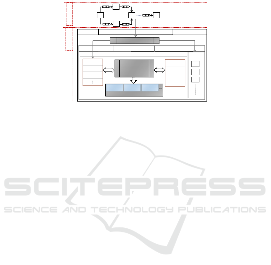
on different classes of DPNs. The overall design flow
is systematically organized in two phases of modeling
and synthesis as shown in Fig. 1. First, the modeling
phase proposes a common general DPN model that
relies on an abstract notion of a process. A process is
composed of a finite set of actions where each action
can perform a computation by consuming tokens from
input buffers and producing tokens to output buffers.
This general model is used with specific constraints
and definitions to specify the precise classes of DPNs.
The underlying modeling language of the proposed
DPN model is the CAL actor language (Eker and
Janneck, 2003). The framework currently supports
two different classes of DPNs, namely the dynamic
dataflow (DDF) MoC and the synchronous (static)
dataflow (SDF) MoC. The DDF MoC allows pro-
cesses whose actions consume different numbers of
inputs and produce different numbers of outputs while
the actions of processes in the SDF MoC all con-
sume the same number of input tokens and produce
the same number of output tokens.
Second, the synthesis part provides a tool chain
that consists of various essential tools including dif-
ferent specialized code generators and runtime sys-
tems for different MoCs. Using the open computing
language (OpenCL) (Stone et al., 2010), it incorpo-
rates a standard hardware abstraction for cross-vendor
heterogeneous hardware architectures. OpenCL of-
fers a programming model consisting of a host and
several kernels where the host is a centralized en-
tity that is connected to one or more computing de-
vices and is responsible for the execution of kernels
(Rafique and Schneider, 2020a). Each kernel is a C
function that actually implements one instance of the
behavior of a system or part of a system. The frame-
work adopts this idea of host and kernels for the syn-
thesis as shown in Fig 1. The synthesis phase uses a
combination of different code generators which gen-
erates an OpenCL kernel for each process in the net-
work based on the underlying class of that process.
The runtime system, in particular, is organized in a
centralized host and kernels architecture, built under
the OpenCL abstraction. The host accommodates dif-
ferent essential components along with the Runtime-
Manager. The Runtime-Manager exploits other com-
ponents of the host and provides different low-level
implementations to finally execute the modeled DPNs
(kernels) on the target hardware.
MODELSWARD 2021 - 9th International Conference on Model-Driven Engineering and Software Development
88

As presented in (Rafique and Schneider, 2020b),
the SDF MoC proved to be the most effective one
in terms of the generated code size, the build time,
and the end-to-end performance. This is mainly be-
cause the SDF MoC only supports statically schedu-
lable systems and therefore generates very succinct
code for static processes. In contrast, the implemen-
tations based on the DDF semantics accommodate ad-
ditional code for enabling the dynamic evaluation of
actions at runtime. The DDF MoC offers semantics to
model static as well as dynamic behaviors, but at the
cost of the additional runtime overhead. Therefore,
it exhibits a trade-off between flexibility and overall
performance. The main challenge is therefore to in-
tegrate a MoC in the framework that is able to cap-
ture dynamic behaviors and that allows one to gener-
ate succinct code.
1.3 Idea and Contributions
Kahn process networks (KPNs) (Kahn and Mac-
Queen, 1977) are dynamic DPNs that exhibit latency-
insensitive deterministic behaviors that do not depend
on the timing or the execution order of the processes.
The KPN MoC is typically specified with the follow-
ing restrictions and properties: (1) Processes are not
allowed to test input buffers for the existence of to-
kens. (2) Reading from input buffers is blocking, and
writing to output buffers is non-blocking. (3) Pro-
cesses must implement deterministic sequential func-
tions. (4) Processes do not need all of their inputs
to get triggered for execution. Based on these re-
strictions/properties, it can be implied that in con-
trast to the DDF MoC, the KPN MoC only triggers
a process for execution if the exact information on in-
puts required to produce the output is available. This
avoids the generation of additional code for processes
to dynamically evaluate actions at runtime, and hence,
avoids the runtime overhead associated with the DDF
MoC. In contrast to the SDF MoC, the KPN MoC
can capture both static as well as dynamic behaviors.
Altogether, the integration of the KPN MoC in the
framework will potentially provide more efficient sys-
tem implementations by combining the flexibility to
support dynamic processes and the ability to produce
succinct kernel code for processes.
In this paper, we therefore integrate the KPN MoC
based on the proposed general model of DPN and
the runtime system of the framework. Since chan-
nels/buffers with unbounded capacity cannot be re-
alized in real implementations, the proposed DPN
model only supports blocking write. However, a
KPN semantics-preserving implementation can use
bounded buffers using blocking read and write (Parks,
1995). In summary, we make the following contribu-
tions in this paper:
• We integrate the KPN MoC in an extendable
model-based design framework, mainly with the
aim to produce more efficient system implemen-
tations in terms of end-to-end performance com-
pared to the already supported MoCs (DDF and
SDF) of the framework.
• We formally describe the integrated KPN MoC
and its corresponding code generator based on the
proposed general model of DPN through struc-
tural operational semantics (SOS).
• We present the extended runtime system for fi-
nally implementing KPN models on the target
hardware.
• We designed a set of simple benchmarks involv-
ing static as well as dynamic behaviors. Each
benchmark is modeled and automatically synthe-
sized three times (when possible): First, based
on the DDF MoC, second using the SDF MoC,
and finally using the newly integrated KPN MoC.
Each generated implementation is evaluated on
two different target hardware platforms. The re-
sults are presented to analyze and to compare the
code size and the end-to-end performance of all
generated implementations.
2 RELATED WORK
Design tools for modeling like Ptolemy (Brooks et al.,
2010) and FERAL (Kuhn et al., 2013) support vari-
ous MoCs including different classes of DPNs. These
frameworks use software components called directors
that control the semantics of the execution of pro-
cesses as well as the communication between them.
However, Ptolemy provides also a preliminary code
generation facility
1
. It requires the supporting helper
code for each process to generate a general C pro-
gram. This helper code is required to be provided
manually using a fairly complex procedure for each
process. Currently, only specific processes have sup-
porting helper code.
Another well known design tool called System-
CoDesigner (Haubelt et al., 2008) supports different
classes of DPNs. It incorporates an actor-oriented be-
havior built on top of SystemC. System-CoDesigner
currently supports only hardware synthesis based on
a commercial tool named Forte’s Cynthesizer.
Design tools for synthesis are moreover limited to
particular MoCs where each framework usually only
1
http://ptolemy.berkeley.edu/ptolemyII/ptII10.0/ptII10.
0.1/ptolemy/cg/
Integrating Kahn Process Networks as a Model of Computation in an Extendable Model-based Design Framework
89

supports a specific DPN class. We present a few ex-
amples of dataflow-oriented synthesis frameworks:
• The framework presented in (Schor et al., 2013)
introduces a design flow for executing applica-
tions specified as SDF graphs on heterogeneous
systems using OpenCL. The main focus of this
work is to develop features to better utilize the
parallelism in heterogeneous architectures.
• The DAL framework (Schor et al., 2012) presents
a scenario-based design flow for mapping stream-
ing applications onto heterogeneous systems. Be-
haviors are modeled based on Kahn process net-
works (KPNs) (Kahn and MacQueen, 1977) and a
finite state machine.
• The work presented in (Lund et al., 2015) trans-
lates DPN models to programs using OpenCL.
The methodology incorporates static analysis and
transformations and confined to the synthesis of
SDF models. Similarly, another dataflow ori-
ented framework (Boutellier et al., 2018) proposes
a MoC as a symmetric-rate dataflow, a restriced
form of SDF where the token production rate and
the token consumption rate per FIFO channel is
symmetric.
Thus, the existing frameworks based on DPNs gen-
erally support the modeling and synthesis of systems
based on a particular MoC, i.e., a specific DPN class.
In contrast, our approach enables the modeling as well
as the automatic software synthesis of systems using
different classes of DPNs, including their heteroge-
neous combinations under the supervision of a com-
mon extendable framework.
3 THE GENERAL MODEL OF
DPN
A general dataflow process network is a triple ℵ =
(D,F,P ), consisting of a data type D, FIFO buffers F
and processes P . The data type D always includes
a special symbol ⊥ ∈ D to indicate the absence of
a value. The semantics of FIFO buffers is a pair
of {i, o} × N where i and o denotes input and out-
put buffers, respectively. Each FIFO buffer f ∈ F
provides a channel to a sequence of tokens over D,
termed as a stream, denoted by X
f
D
. Following that,
~
X
F
D
is the set of all finite sequences of tokens over
D. For convenience, we simply denote the contents of
buffers by X
∗
D
. P is the finite set of processes. Each
process p = (F
in
,F
out
,Act) ∈ P consists of a list of
input buffers F
in
, a list of output buffers F
out
, and an
associated set of actions Act. The input and output
buffers of a process are always mutually exclusive,
i.e., F
in
∩ F
out
= {}. We further organize each process
in a set of what we call actions Act.
3.1 The Basic Structure of Actions
Each action act = (F
act
i
,F
act
o
,
~
V
act
i
,
~
V
act
o
) ∈ Act con-
sists of a list of input buffers F
act
i
⊆ F
in
, a list of out-
put buffers F
act
o
⊆ F
out
, a list of sequences of input
token variables
~
V
act
i
of F
act
i
, and a list of sequences
of output token variables
~
V
act
o
of F
act
o
. All sequences
∈
~
V
act
= (
~
V
act
i
,
~
V
act
o
) contain a list of local variables
for temporary storage of data and are exclusive to a
single action. Each sequence ∈
~
V
act
i
contains a list
of local variables, denoting a finite sequence of in-
put tokens that will be consumed per execution of an
action from its respective input buffer ∈ F
act
i
. Sim-
ilarly, each sequence ∈
~
V
act
o
contains a list of local
variables, denoting a sequence of output tokens that
will be produced per execution of an action in its re-
spective output buffer ∈ F
act
o
. For an action with ’t’
inputs F
act
i
= {F
i
1
, F
i
2
..., F
i
t
} providing input streams
~
X
F
act
i
D
= {X
F
i
1
D
, X
F
i
2
D
..., X
F
i
t
D
}, the corresponding se-
quences of local input variables are defined by
~
V
act
i
=
{V
act
i
1
,V
act
i
2
,...,V
act
i
t
}. Each sequence V
act
i
j
∈
~
V
act
i
consists of a finite number of input token variables.
For instance, if F
i
j
has a sequence of ’q’ tokens per
action execution, the corresponding list of local vari-
ables is defined by V
act
i
j
= {v
act
i
j 1
,v
act
i
j 2
,...,v
act
i
j q
}. The
number of token variables in each sequence, denoted
by L(V
act
i
j
), determines the token consumption rate
per execution of the corresponding input buffer.
Similarly, an action with ’l’ outputs F
act
o
=
{F
o
1
, F
o
2
..., F
o
l
} is defined with the correspond-
ing sequences of local output variables
~
V
act
o
=
{V
act
o
1
,V
act
o
2
,...,V
act
o
l
}. Each sequence V
act
o
j
∈
~
V
act
o
consists of a finite number of output token variables.
The number of token variables in each sequence, de-
noted by L(V
act
o
j
), determines the token production
rate per execution of the corresponding output buffer.
This structure of inputs and outputs of actions is illus-
trated in Listing 1 and Listing 2 (Lines 1 and 6). The
declaration of inputs and outputs is separated by the
identifier ’==>’.
For an action that requires input tokens to have
particular values, an additional condition can be spec-
ified using a guard (Lines 2 and 7, in Listing 1 and
Listing 2). The inputs used for guards (guarded in-
puts) and their corresponding token variables are de-
noted by F
act
γ
⊆ F
act
i
and
~
V
act
γ
⊆
~
V
act
i
, respectively.
In particular, a guard is composed of a list of Boolean
MODELSWARD 2021 - 9th International Conference on Model-Driven Engineering and Software Development
90

Listing 1: Dynamic split using the proposed model.
1 act
1
: action F
i
1
:[v
act
1
i
1 1
] ,F
i
2
:[v
act
1
i
2 1
] = = > F
o
1
:[v
act
1
o
1 1
]
2 guard v
act
1
i
1 1
= 1
3 do
4 v
act
1
o
1 1
:= v
act
1
i
2 1
;
5 end
6 act
2
: action F
i
1
:[v
act
2
i
1 1
] ,F
i
2
:[v
act
2
i
2 1
,v
act
2
i
2 2
] = = > F
o
1
:[v
act
2
o
1 1
] ,F
o
2
:[
v
act
2
o
2 1
]
7 guard v
act
2
i
1 1
= 2
8 do
9 v
act
2
o
1 1
:= v
act
2
i
2 1
; v
act
2
o
2 1
:= v
act
2
i
2 2
;
10 end
expressions E
act
B
= {E
act
B
1
,E
act
B
2
,...,E
act
B
n
}, where n ∈
N. Each expression ∈ E
act
B
can be applied on an in-
dividual input token variable. A guard consisting of
a list of Boolean expressions E
act
B
is therefore ap-
plied on a list of individual token variables denoted
by V
act
E
γ
⊆
S
~
V
act
γ
.
3.2 Basic Definitions for Actions
For any action act in a defined behavior of a process to
be fired, there exists two necessary conditions and the
additional condition of a guard (if used): First, there
must be enough input tokens available as specified by
the sequences of input token variables
~
V
act
i
in F
act
i
.
Second, there must be enough space available as spec-
ified by the sequences of output token variables
~
V
act
o
in F
act
o
. Finally, the required values on the guarded
inputs must be available, i.e., the guard must be true.
These conditions can be described with the following
definitions:
Definition 1 (Input Constraint (δ
1
a
)). For an action
act ∈ Act to be fired, each sequence of token variables
∈
~
V
act
i
must be a prefix of the sequence of tokens
available on the corresponding input buffer (where
s
1
v s
2
means that s
1
is a prefix of s
2
): ∀V
act
i
j
∈
~
V
act
i
,V
act
i
j
v X
F
i
j
D
.
Definition 2 (Output Constraint (δ
1
b
)). For an action
act ∈ Act to be fired, each output ∈ F
act
o
must contain
space for the corresponding sequence of output token
variables ∈
~
V
act
o
. Overall, this yields:
∀F
o
j
∈ F
act
o
, (size(F
o
j
) − count(X
F
o
j
D
)) ≥ L (V
act
o
j
)
where
• size( f ) returns the total size ∈ Z of the buffer f ,
and
• count(X
f
D
) returns the current count ∈ Z, i.e., the
available number of tokens in the buffer f .
Listing 2: Dynamic merge using the proposed model.
1 act
1
: action F
i
1
:[v
act
1
i
1 1
] ,F
i
2
:[v
act
1
i
2 1
] = = > F
o
1
:[v
act
1
o
1 1
]
2 guard v
act
1
i
1 1
= 1
3 do
4 v
act
1
o
1 1
:= v
act
1
i
2 1
;
5 end
6 act
2
: action F
i
1
:[v
act
2
i
1 1
] ,F
i
2
:[v
act
2
i
2 1
] ,F
i
3
:[v
act
2
i
3 1
] = = > F
o
1
:[v
act
2
o
1 1
,
v
act
2
o
1 2
]
7 guard v
act
2
i
1 1
= 2
8 do
9 v
act
2
o
1 1
:= v
act
2
i
2 1
; v
act
2
o
1 2
:= v
act
2
i
3 1
;
10 end
Definition 3 (Guard Constraint (δ
2
)). For an action
act ∈ Act to be fired, the combined evaluation of all
Boolean expressions must evaluate to 1 (true). With
B = {0, 1}, this yields:
∀act ∈ Act, (E
act
B
(V
act
E
γ
) → B )
!
= 1
Upon firing, each action performs the desired compu-
tation defined within do/end construct, as illustrated
in Listing 1 and Listing 2 (Lines 3-5, Lines 8-10).
4 KPN FORMULATION AND
OPERATIONAL SEMANTICS
In this section, we formulate the KPN MoC and de-
fine its operational semantics based on the proposed
general model of DPN, as presented in Section 3.
We introduce a state transition system of a DPN by
Σ = hAct, M
F
,M
V
i. The behavior of a process is de-
scribed by a set of actions Act = {act
1
,act
2
,...,act
n
}
where n ∈ N. Each act ∈ Act is of the form l:
~
V
act
|
~
X
F
act
i
D
|
i
→
~
V
act
|
~
X
F
act
o
D
|
o
that upon firing consumes to-
kens as specified by
~
V
act
i
from the corresponding
streams of F
act
i
and produces tokens as specified by
~
V
act
o
to the corresponding streams of F
act
o
. The la-
bels l of actions are mutually exclusive. For all FIFO
buffers, the function M
F
: F → X
∗
D
maps each buffer
f to a sequence of data values (tokens) of data type
D. Similarly, for all sequences of local token vari-
ables, the function M
V
:
~
V → D maps each local to-
ken variable to a data value of type D. The KPN MoC
formulation and operational semantics are elaborated
formally based on the state transition system Σ.
4.1 Organization of Actions
Each process p ∈ P can be composed of a set of
actions ∈ Act with guards. The inputs and out-
puts and their associated number of token variables
Integrating Kahn Process Networks as a Model of Computation in an Extendable Model-based Design Framework
91

(i.e., token consumption and production rates) can
be different across different actions with the excep-
tion of guarded inputs. In particular, the inputs used
for guards (guarded inputs) across all actions in a
process have at least one common input. This im-
plies that for any pair of guarded actions in a process
F
act
1
i
∩ F
act
2
i
6= {}. The consumption rates of guarded
inputs are always same across actions in a process,
i.e., L(
~
V
act
1
γ
) = L (
~
V
act
2
γ
). For convenience we sim-
ply denote all guarded inputs in a process and their
token variables by F
p
γ
and
~
V
p
γ
, respectively. Second,
the Boolean expressions E
B
of guards are always ap-
plied on the same tokens in inputs F
act
γ
provided by
different token variables across actions. However, the
Boolean expressions E
B
of guards are always exclu-
sive, e.g., E
act
1
B
∩ E
act
2
B
= {}. These restrictions facil-
itate the imposition of sequential function implemen-
tations in processes. In particular, they ensure that
for each execution of a process, the actions will never
compete for an execution for any set of tokens. They
enable the execution of processes with dynamic data
rates and dynamic data paths, mainly dependent on
which guards are enabled on each execution.
Examples. Two different dynamic processes,
namely the dynamic split (d-split) and the dynamic
merge (d-merge) are illustrated in Listing 1 and List-
ing 2, respectively. The d-split process consists of two
actions (act
1
and act
2
) that depending on the value of
token at input F
i
1
split the tokens from input F
i
2
to
outputs F
o
1
and F
o
2
. Both actions use the same input
F
i
1
for the guard, declared with the same consumption
rate (Lines 1 and 6). The guard is composed of dif-
ferent exclusive Boolean expressions (Lines 2 and 7).
Both actions declare the input F
i
2
with different con-
sumption rates i.e., L (V
act
1
i
2
) 6= L (V
act
2
i
2
) (Lines 1 and
6). The action act
2
has an additional output F
o
2
. On
the contrary, the d-merge process depending on the
value of token at input F
i
1
merges the tokens from in-
puts F
i
2
and F
i
3
to output F
o
1
. Both actions in d-merge
declare the guarded input F
i
1
with the same consump-
tion rate (Lines 1 and 6), which is used with differ-
ent exclusive guard expressions (Lines 2 and 7). The
action act
2
has an additional input F
i
3
. Both actions
declare output F
o
1
with different production rates i.e.,
L(V
act
1
o
1
) 6= L (V
act
2
o
1
) (Lines 1 and 6).
4.2 Evaluation and Execution of Actions
As discussed, the KPN MoC does not allow processes
to test input buffers for the existence of tokens. A
process is only triggered for execution if the exact in-
formation on inputs required to execute an action is
available. Therefore, each time a process p ∈ P is
triggered for an execution, a particular action is exe-
cuted, mainly dependent on which guard is enabled.
The guards of actions ∈ Act are always evaluated se-
quentially in the same order of their actions defini-
tions. This execution of actions is formally described
using the state transition system Σ with two specific
rules. Definitions 4-7 (i.e., Rules 1-4) have already
been proposed for the existing DDF and SDF MoCs
of the framework in (Rafique and Schneider, 2020b).
Definition 8 (Rule 5, PREPARE (ρ
5
)). This rule is
fired to read the specified fixed number of tokens
~
V
p
γ
without consuming them from all inputs F
p
γ
used for
guards in a process p ∈ P . It is formally described as:
∅
hAct, M
F
,M
V
i → hAct, M
F
,M
0
V
i
with, M
0
V
= M
V
[
~
V
p
γ
].
Therefore, a finite number of tokens designated by
~
V
p
γ
are read (not consumed) from streams
~
X
F
p
γ
D
pro-
vided by the guarded inputs F
p
γ
.
Definition 9 (Rule 6, PROCEED (ρ
6
)). An action
act
1
∈ Act fires for an execution if the required val-
ues on the guarded inputs are available, i.e., the guard
is true. It is formally described as:
(act
1
∈ Act, δ
2
)
hAct, M
F
,M
V
i → hAct, M
0
F
,M
0
V
i
with M
0
F
= M
F
[F
act
1
i
,F
act
1
o
],M
0
V
= M
V
[
~
V
act
1
i
,
~
V
act
1
o
].
Therefore, a finite number of tokens
~
V
act
1
i
are con-
sumed from streams
~
X
F
act
1
i
D
provided by the inputs
F
act
1
i
, the defined computation is performed, and a fi-
nite number of tokens
~
V
act
1
o
are produced to streams
~
X
F
act
1
o
D
.
4.3 Triggering Processes for Execution
The KPN MoC only triggers a process for execution
if the exact information on inputs required to produce
the output is available. Therefore, each process p ∈ P
is triggered for an execution if there exists at least
one action act ∈ Act having: enough tokens as speci-
fied by
~
V
act
i
in inputs F
act
i
, enough space as specified
by
~
V
act
o
in outputs F
act
o
, and required values on the
guarded inputs F
act
γ
. This can be formally defined as:
∀p ∈ P ∃act ∈ Act. (δ
1
,δ
2
) = true
When a process is triggered for an execution, the ac-
tions are executed based on the proposed rules ρ
5
and
ρ
6
.
MODELSWARD 2021 - 9th International Conference on Model-Driven Engineering and Software Development
92

5 KPN SYNTHESIS
The synthesis phase of the framework, as shown in
Fig. 1, provides a tool chain including code genera-
tors for specific MoCs and the runtime system. These
tools work together and finally implement the mod-
eled systems on the target hardware based on the un-
derlying semantics of the used MoCs (i.e., classes of
DPNs). In particular, a code generator is designed
and developed based on the underlying semantics of
each used DPN class. Each code generator generates
an OpenCL kernel for each process based on the un-
derlying DPN class. Second, the runtime system is
organized in a centralized host and kernels program
model, built under the OpenCL abstraction. The host
features different components including the Runtime-
Manager that schedule and execute processes (gener-
ated kernels) on the target hardware.
The complete synthesis phase and the associ-
ated tool chain is presented in detail in (Rafique and
Schneider, 2020b). In this section, we mainly present
the tools extended to support the synthesis of KPN
models. This includes the specialized code genera-
tor designed for generating kernels based on the KPN
MoC, and the extended Runtime-Manager for finally
implementing KPN models on the target hardware.
Algorithm 1: Code generation of the KPN MoC.
1 foreach process p ∈ P in Network ℵ do
2 PREPARE(ρ
5
){
3 peek(for all guarded inputs of this process)}
4 foreach action act ∈ Act in a process p do
5 evaluate all guard expressions E
act
B
6 if δ
2
then
7 PROCEED(ρ
6
){
8 read(for all inputs of this action)}
9 perform modeled computations()
10 write(for outputs of this action)}
11 end
12 end
13 end
5.1 KPN Code Generation
Prior to presenting the KPN code generation, we first
introduce some additional execution primitives using
the state transition system Σ:
The read(F
i
j
,V
act
i
j
,L(V
act
i
j
)) method consumes a
number of tokens as specified by L (V
act
i
j
) from the in-
put buffer F
i
j
, and stores them in the temporary input
token variables V
act
i
j
:
read(F
i
j
,V
act
i
j
,L(V
act
i
j
))
hAct, M
F
,M
V
i → hAct, M
0
F
,M
0
V
i
with M
0
F
= M
F
[F
i
j
], M
0
V
= M
V
[V
act
i
j
].
The peek(F
i
j
,V
act
i
j
,L(V
act
i
j
)) method reads a
number of tokens (without consuming them) as spec-
ified by L (V
act
i
j
) from the input buffer F
i
j
, by simply
copying them into the temporary input token variables
V
act
i
j
:
peek(F
i
j
,V
act
i
j
,L(V
act
i
j
))
hAct, M
F
,M
V
i → hAct, M
F
,M
0
V
i
with M
0
V
= M
V
[V
act
i
j
].
The write(F
o
j
,V
act
o
j
,L(V
act
o
j
)) method writes a
number of tokens as specified by L(V
act
o
j
) from the
output token variables V
act
o
j
into the output buffer F
o
j
:
write(F
o
j
,V
act
o
j
,L(V
act
o
j
))
hAct, M
F
,M
V
i → hAct, M
0
F
,M
V
i
with M
0
F
= M
F
[F
o
j
].
The code generation based on the underlying se-
mantics of the KPN MoC is shown in Algorithm 1.
The fundamental principle of the KPN code gener-
ation is based on the dynamic execution of actions
using the proposed rules (ρ
5
and ρ
6
) of the underly-
ing KPN semantics. For each process p ∈ P in the
network ℵ, the proposed algorithm works as as de-
scribed in the followning.
First, the code is generated to fire the rule ρ
5
(PREPARE) (Lines 2-3). To this end, the peek
method is inserted for all guarded inputs of a pro-
cess (Line 3). The algorithm then iterates through the
set of modeled actions in the order of their definitions
(Line 4), where for each action ∈ Act, it proceeds as
follows: First, the code is generated to evaluate all
the guarded Boolean expressions E
act
B
(Line 5). Next,
the code is generated to evaluate and fire the rule ρ
6
(PROCEED) (Lines 6-11). For ρ
6
, first, the code is
generated to read (consume) all the inputs of an action
(Line 8). For this purpose, the read method is inserted
for each input of an action. Second, the generated
code for the modeled computations is inserted, prior
to generating code for writing the computed results
on the outputs (Lines 9-10). For writing, the write
method is inserted for outputs based on the modeled
computations of an action.
The generated kernel for d-split as illustrated in
Listing 1 is listed in Listing 3. The code generator
generates generic kernel code to enable the central-
ized host to dispatch multiple execution (instances) of
kernels on the device at a time. However, for brevity,
we only list and focus on the kernel code generated
based on the KPN semantics. For better correspon-
dence, we use the same conventions for inputs/out-
Integrating Kahn Process Networks as a Model of Computation in an Extendable Model-based Design Framework
93

Listing 3: Generated kernel for d-split.
1 _ k er n el v oi d d- s p l it ( __ gl o ba l f i fo _t * F
i
1
, __g l ob a l
fi f o _ t * F
i
2
, __g l ob a l f if o_ t * F
o
1
, __g l ob a l f if o_ t
* F
o
2
) {
2 __ pr i va t e u i n t V
i
1
[L(V
act
1
i
1
)];
3 __ pr i va t e u i n t V
i
2
[L(V
act
2
i
2
)];
4 __ pr i va t e u i n t V
o
1
[L(V
act
1
o
1
)];
5 __ pr i va t e u i n t V
o
2
[L(V
act
2
o
2
)];
6 uin t * v
act
1
i
1 1
= &V
i
1
[0 ]; u in t * v
act
2
i
1 1
= &V
i
1
[0 ];
7 uin t * v
act
1
i
2 1
= &V
i
2
[0 ]; u in t * v
act
2
i
2 1
= &V
i
2
[0 ];
8 uin t * v
act
2
i
2 2
= &V
i
2
[1 ]; u in t * v
act
1
o
1 1
= &V
o
1
[0 ];
9 uin t * v
act
2
o
1 1
= &V
o
1
[0 ]; u in t * v
act
2
o
2 1
= &V
o
2
[0 ];
10 /
*
PREPARE(ρ
5
)
*
/
11 pee k (F
i
1
, V
i
1
, 1 ) ;
12 /
*
PROCEED(ρ
6
): act1
*
/
13 if (*v
act
1
i
1 1
== 1) {
14 re ad (F
i
1
, V
i
1
, 1 ) ;
15 re ad (F
i
2
, V
i
2
, 1 ) ;
16 *v
act
1
o
1 1
= *v
act
1
i
2 1
;
17 by te s = wri te (F
o
1
, V
o
1
, 1 ) ; }
18 /
*
PROCEED(ρ
6
): act2
*
/
19 els e if ( * v
act
2
i
1 1
== 2) {
20 re ad (F
i
1
, V
i
1
, 1 ) ;
21 re ad (F
i
2
, V
i
2
, 2 ) ;
22 *v
act
2
o
1 1
= *v
act
2
i
2 1
; *v
act
2
o
2 1
= *v
act
2
i
2 2
;
23 by te s = wri te (F
o
1
, V
o
1
, 1 ) ;
24 by te s = wri te (F
o
2
, V
o
2
, 1 ) ; }
25 }
puts as were used throughout the paper. The gener-
ated code can be explained as described in the follow-
ing.
First, the arrays are declared for the sequences of
input/output token variables (Lines 2-5). In each ex-
ecution of a KPN process, only a particular action
is executed, which depends on the enabled guards.
To avoid unnecessary duplication, an array is de-
clared for each input/output with the highest con-
sumption/production rate of all actions. For instance,
an array is declared for the input F
i
2
with the high-
est consumption rate L(V
act
2
i
2
) of both actions (Line
3). Second, the individual input/output token vari-
ables are declared and pointed to their respective se-
quences i.e., arrays (Lines 6-9). Next, the rule ρ
5
(PREPARE) is followed to peek the tokens from the
inputs used for guards (Line 10-11). Finally, the rule
ρ
6
(PROCEED) is invoked to execute a particular ac-
tion (i.e., either act
1
or act
2
) based on the activation
of guard. To this end, if the guard is true for act
1
, a
single token is consumed from F
i
2
and written to the
output F
o
1
(Lines 13-17). On the other hand, if the
guard is true for act
2
, two tokens are consumed from
F
i
2
, where the first token is written to F
o
1
, and the
other to F
o
2
(Lines 19-24).
5.2 KPN Runtime-Manager
General Workflow. The Runtime-Manager is a
part of the host that uses the Process-Queue and
the Device-Queue as shown in Fig. 1 and provides
the schedulers for triggering processes for execution
based on the used MoCs, a dispatcher for mapping
processes executions to devices, and a communica-
tion and synchronization mechanism between the host
and kernels. The Process-Queue provides the de-
sired information about each process to the Runtime-
Manager such as the associated FIFO buffers, the pro-
cess’s status (idle, running or blocked), the associ-
ated kernel, etc. The Device-Queue lists all the avail-
able devices of the target hardware using the OpenCL
specification. Each element of this queue provides
a command queue of a device where the processes
can be dispatched for execution. While a scheduler
fetches a ready process from the Process-Queue based
on the underlying MoC, the dispatcher finds the de-
vice from the Device-Queue with the least load and
maps the fetched process on that device. The gener-
ated kernel of the dispatched process is then executed
based on the used MoC. The data communication be-
tween the host (FIFO buffers) and the OpenCL de-
vice is carried out using OpenCL buffers. For each
bounded FIFO buffer, an OpenCL buffer is created
with the same design and size of the FIFO buffer.
When all the dispatched instances of the kernel are
executed, the Runtime-Manager is then automatically
notified to update the components using a synchro-
nization mechanism. During synchronization, a set of
general tasks are performed including retrieving data
from OpenCL buffers, updating all the FIFO buffers
of the process, updating the Process-Queue as well as
device’s load and so on.
KPN Extension. The communication and syn-
chronization mechanism is common to all DPN
classes of the framework including the newly inte-
grated KPN MoC. Second, as the main aim of this
work is to analyze and evaluate the artifacts exhib-
ited by the underlying semantics of particular MoCs
in real world. The same dispatcher is used for map-
ping execution on devices for the KPN MoC as used
for existing MoCs in (Rafique and Schneider, 2020b).
Schedulers are designed for triggering processes
for execution based on the underlying MoCs, and are
therefore MoC dependent. To trigger processes for
execution based on the KPN semantics, as described
in Section 4.3, the Runtime-Manager is extended with
a specialized KPN scheduler. The KPN MoC only
triggers a process for execution if the exact infor-
mation on inputs/outputs required to fire an action is
available. Since the host and generated kernels are in-
MODELSWARD 2021 - 9th International Conference on Model-Driven Engineering and Software Development
94

dependent components, this information is required
to be extracted from modeled processes at compile
time. The extracted information can be used by the
KPN scheduler at runtime to trigger processes for ex-
ecution. To this end, we propose a systematic way of
extracting the information by introducing the input-
output tree wrapper (IOT-wrapper).
5.2.1 Introducing IOT-wrapper
The IOT-wrapper wraps the exact information of in-
puts/outputs required to trigger a process in a standard
tree structure, while taking into account the underly-
ing semantics of the KPN MoC. For each process in a
network, a wrapper is generated at compile time from
the modeled behavior. The IOT-wrapper generation
based on the underlying KPN semantics is shown in
Algorithm 2. For each process p ∈ P in the network
ℵ, the proposed algorithm works as follows:
The IOT-wrapper is initialized, first, by adding the
root node, and second, by generating and assigning
a function StepFunction to the root node (Lines 2-
5). The StepFunction of the root node is generated
with the code specifically related to the guards (Line
5) and hence also termed as guard node. In partic-
ular, the code is generated for each action in the or-
der in which actions were defined to first check if
each input used for guard (F
γ
j
∈ F
act
γ
) has enough to-
kens (V
act
γ
j
v X
F
γ
j
D
), and second to evaluate the guard
(E
act
B
(V
act
E
γ
) → B). For each action, if the guard is
true, the StepFunction returns a different number num
∈ Z that corresponds to a specific branch in the tree
originating from the root node. The algorithm then
iterates through the modeled set of actions Act in
the order of there definitions (Line 7). For each ac-
tion act ∈ Act, the algorithm adds nodes for all non-
guarded inputs (F
act
i
\F
act
γ
) and all outputs (F
act
o
). For
each non-guarded input and each output in act, the
algorithm proceeds as follows: First, if the current
node is the root node, a new node is added at a spe-
cific branch of the root node provided by the variable
num (Line 11), which is incremented by 1 for each
action (Line 15). On the contrary, if the current node
is not the root node, a new node is always added at the
branch 0 (leftest) of the current node (Line 19). Sec-
ond, for a non-guarded input node, the StepFunction
is generated with the code to check if that input (F
i
j
)
has enough tokens (V
act
i
j
v X
F
i
j
D
) (Line 13). For an
output node, the StepFunction is generated with the
code to check if that output (F
o
j
) has enough space
(size(F
o
j
) − count(X
F
o
j
D
) ≥ L (V
act
o
j
) (Line 14).
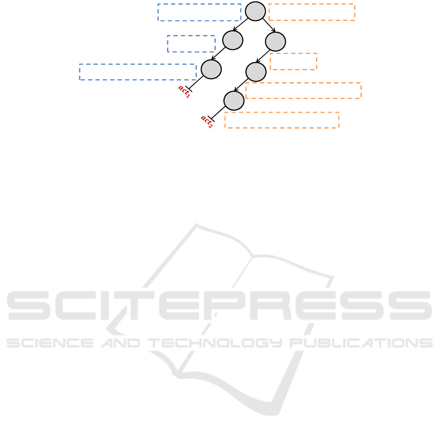
The IOT-wrapper generated for d-split, as illus-
trated in Listing 1, is shown in Figure 2. The root
node only involves the input F
i
1
as it is the only input
used for guard by d-split. The StepFunction gener-
ated and assigned to each node is shown mathemati-
cally in dashed boxes. The set of branches originat-
ing from the root node and extending up to the leaf
node represents a particular action. For instance, act
2
is represented by branches originating from the root
node (F
i
1
) and extending up to the leaf node (F
o
2
).
Algorithm 2: IOT-wrapper generation.
1 foreach process p ∈ P in Network ℵ do
2 Initialize IOT-wrapper{
3 add root (guard) node
4 for root node, generate StepFunction{
5 ∀act ∈ Act, [∀V
act
γ
j
∈
~
V
act
γ
, V
act
γ
j
v X
F
γ
j
D
∧
E
act
B
(V
act
E
γ
) → B] }}
6 Initialize num to 0
7 foreach act ∈ Act do
8 current node = root node
9 foreach ( (F
i
j
∈ F
act
i
\ F
act
γ
) ∧ (F
o
j
∈ F
act
o
) ) do
10 if current node == root node then
11 new node = add child node to current node
at branch num
12 for new node, generate StepFunction{
13 V
act
i
j
(∈
~
V
act
i
\
~
V
act
γ
) v X
F
i
j
D
∨
14 size(F
o
j
) − count(X
F
o
j
D
) ≥ L (V
act
o
j
) }
15 increment num by 1
16 current node = new node
17 end
18 else
19 new node = add child node to current node
at branch 0
20 for new node, generate StepFunction{
same as Lines 13-14 }
21 current node = new node
22 end
23 end
24 end
25 end
5.2.2 KPN Scheduler based on IOT-wrapper
The KPN scheduler is provided with the generated
IOT-wrappers of all processes in the used network.
It uses a variant of depth-first search (DFS) method
(Tarjan, 1972) that starts at the root of the tree, selects
a branch, and traverses through that branch as deep
as possible until the leaf node is reached. In gen-
eral, for each node, the scheduler calls the assigned
StepFunction, and only moves to the next node if the
function returns true. In particular, the StepFunction
of the root node returns a number num ∈ Z mainly
dependent on which guard is true. This number is
Integrating Kahn Process Networks as a Model of Computation in an Extendable Model-based Design Framework
95
KPN MoC:‘dynamic split’ IOT-Wrapper
1
𝒂𝒄𝒕𝟏
𝒂𝒄𝒕𝟐
1. act1: action 𝐹
: [𝑣
_
], 𝐹
: [𝑣
_
] ==> 𝐹
: [𝑣
_
]
2. guard 𝑣
_
= 1
3. do
4.
𝑣
_
:= 𝑣
_
;
5. end
6. act2: action 𝐹
: [𝑣
_
], 𝐹
: [𝑣
_
, 𝑣
_
] ==> 𝐹
: [𝑣
_
], 𝐹
: [𝑣
_
]
7. guard 𝑣
_
= 2
8. do
9. 𝑣
_
:= 𝑣
_
;
10. 𝑣
_
:= 𝑣
_
;
11. end
𝑭
𝒊
𝟏
𝑭
𝒊
𝟐
𝑭
𝒊
𝟐
𝓥
𝒊
𝟏
𝒂𝒄𝒕
𝟏
⊑ 𝑿
𝑫
𝑭
𝒊
𝟏
&& 𝒗
𝒊
𝟏_𝟏
𝒂𝒄𝒕
𝟏
= 1
𝓥
𝒊
𝟏
𝒂𝒄𝒕
𝟐
⊑ 𝑿
𝑫
𝑭
𝒊
𝟏
&& 𝒗
𝒊
𝟏_𝟏
𝒂𝒄𝒕
𝟐
= 2
𝓥
𝒊
𝟐
𝒂𝒄𝒕
𝟏
⊑ 𝑿
𝑫
𝑭
𝒊
𝟐
𝓥
𝐢
𝟐
𝐚𝐜𝐭
𝟐
⊑ 𝐗
𝐃
𝐅
𝐢
𝟐
(size(𝑭
𝒐
𝟏
) – count(𝑿
𝑫
𝑭
𝒐
𝟏
)) ≥ 𝓛(𝓥
𝒐
𝟏
𝒂𝒄𝒕
𝟏
)
(size(𝐅
𝐨
𝟐
) – count(𝐗
𝐃
𝐅
𝐨
𝟐
)) ≥ 𝓛(𝓥
𝐨
𝟐
𝐚𝐜𝐭
𝟐
)
(size(𝐅
𝐨
𝟏
) – count(𝐗
𝐃
𝐅
𝐨
𝟏
)) ≥ 𝓛(𝓥
𝐨
𝟏
𝐚𝐜𝐭
𝟐
)
𝑭
𝒐
𝟏
𝑭
𝒐
𝟐
𝑭
𝒐
𝟏
Figure 2: IOT-wrapper for d-split.
used to select a specific branch originating from the
root node that directs to a specific action for which
the guard is true. In case if the leaf node is reached
and its StepFunction returns true, the scheduler trig-
gers the process for execution. On the contrary, if the
StepFunction of one of the nodes returns false, the
process gets blocked until that node returns true.
6 EXPERIMENTAL EVALUATION
6.1 Benchmarks
We designed a set of simple benchmarks involving
static as well dynamic behaviors. These benchmarks
are typically designed to offer a variety of processes
that enable the evaluation and comparison of imple-
mentations based on all three different MoCs of the
framework. Each benchmark is organized in a net-
work of three processes which are connected in a
producer-worker-consumer setting. While the pro-
ducer process produces the source data, the consumer
process displays the results of the benchmark. The
worker process performs the main operation, e.g., the
d-split process illustrated in Listing 1. The list of
benchmarks is shown in Table 1.
The SWITCH benchmark is designed to switch
one of several input channels through to a single com-
mon output channel by the application of a control
input. In contrast, the DWORKER benchmark per-
forms the opposite operation by taking one single in-
put channel and switching it to any one of a number of
individual output channels, one at a time. The DITE
benchmark is a dynamic version of the if-then-else
operation that sequentially consumes data from input
channels based on the value of data on a control input.
In contrast, the SITE benchmark, a static version of
the if-then-else operation, always consumes data from
all input channels in parallel. The DMERGE bench-
mark is based on the d-merge process, as illustrated in
Listing 2. It is designed to merge several input chan-
nels to a single common output channel by the ap-
plication of a control input. In contrast, the DSPLIT
benchmark, based on the d-split process as illustrated
in Listing 1, splits a single input channel to a num-
ber of individual output channels. Apart from SITE,
which only offers a static behavior, all other bench-
marks provide dynamic behaviors.
Each benchmark is modeled and automatically
synthesized (when possible) based on all three sup-
ported MoCs of the framework. Thereby, generat-
ing three different implementations, namely the DDF
MoC version, the SDF MoC version and the KPN
MoC version. The end-to-end performance, i.e., the
total execution time of the network to process the
complete input data set including initialization and
termination of the program is considered as the com-
parison metric. The data set used has a maximum of
10,000 samples per input and the average of 50 repe-
titions is taken for each version.
6.2 Experimental Setup
We executed the generated versions of benchmarks on
the following hardware:
• Intel i5-4460 @ 3.20GHz CPU
• AMD Radeon HD 5450 GPU
• 8GB RAM
The software environment used for execution is:
• AMD Radeon HD 5450 Driver Version
15.201.1151.1008
• Intel OpenCL SDK Version 6.3.0.1904
• Windows 10 Pro Version 1903 Build 18362.720
6.3 Evaluation
The generated implementations for each benchmark
based on all three MoCs are evaluated based on their
code size and the end-to-end performance.
MODELSWARD 2021 - 9th International Conference on Model-Driven Engineering and Software Development
96
28
Results: comparison - CPU
0
10
20
30
40
50
60
70
1K 2K 5K 8K 10K
DDF: 'DMERGE' KPN: 'DMERGE'
DDF: 'DSPLIT' KPN: 'DSPLIT'
DDF: 'DWORKER' KPN: 'DWORKER'
DDF: 'SWITCH' KPN: 'SWITCH'
SDF: 'SITE' DDF: 'SITE'
KPN: 'SITE' DDF: 'DITE'
KPN: 'DITE'
Average Execution Time (secs)
Number of Samples
Figure 3: Performance comparison of all classes on CPU.
6.3.1 Generated Code Size
The generated code size of each benchmark for the
complete network based on all three MoCs is depicted
in Table 1. The code size for each generated ver-
sion (implementation) of benchmark is measured as
the sum of lines of code of all generated kernels for
that version. Since the SDF MoC only supports static
behaviors, it can only model and synthesize the SITE
benchmark.
Discussion. The SDF MoC only supports static
behaviors and therefore triggers a process when the
data/space is available for all inputs/outputs. Hence,
it generates very succinct kernel code for static pro-
cesses as observed in the case of SITE. The KPN
MoC also supports dynamic behaviors, however, only
triggers a process for execution when the exact in-
formation on inputs/outputs required to fire an ac-
tion is available. In contrast, the DDF MoC dynam-
ically evaluates actions including their inputs/outputs
when the process is triggered for execution. There-
fore, it accommodates additional code for enabling
the dynamic evaluation of actions within kernels at
runtime. This overhead can therefore be observed
from the number of lines of the generated code for
each benchmark. In particular, the generated code
based on the DDF MoC for SITE is 147% and 136%
greater than the SDF and KPN versions, respectively.
The same trend has been observed for dynamic bench-
marks. The biggest difference is recorded in DITE
where the generated code based on the DDF MoC is
122% greater than the KPN version.
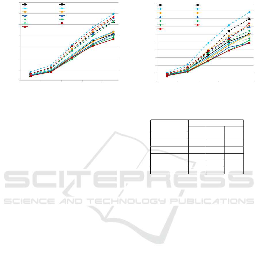
6.3.2 End-to-End Performance
Each generated version of a benchmark is either ex-
ecuted on the CPU or the GPU at a time to evaluate
and compare the end-to-end performance of all used
29
Results: comparison GPU
0
0.5
1
1.5
2
2.5
3
3.5
4
4.5
5
1K 2K 5K 8K 10K
DDF: 'DMERGE' KPN: 'DMERGE'
DDF: 'DSPLIT' KPN: 'DSPLIT'
DDF: 'DWORKER' KPN: 'DWORKER'
DDF: 'SWITCH' KPN: 'SWITCH'
SDF: 'SITE' DDF: 'SITE'
KPN: 'SITE' DDF: 'DITE'
KPN: 'DITE'
Average Execution Time (secs)
Number of Samples
Figure 4: Performance comparison of all classes on GPU.
Table 1: Generated code size of each process.
Benchmarks
Lines of Code
SDF DDF KPN
SWITCH - 148 74
DWORKER - 124 56
DITE - 140 63
SITE 63 156 66
DMERGE - 142 66
DSPLIT - 152 78
MoCs. On each target hardware, i.e., the CPU and
the GPU, the average execution time of each gener-
ated version of a benchmark is measured against the
number of data samples as shown in Fig. 3 and Fig. 4,
respectively.
Discussion. Regardless of which target hardware
is used, the average execution time of each benchmark
version increases with the increase in the number of
data samples. On the CPU, in general, the KPN MoC
performed substantially better than the DDF MoC as
shown in Fig. 3. In particular, for the only static
benchmark, i.e., SITE, the KPN MoC version is about
36% faster than the DDF MoC version. For SITE,
the SDF MoC performed only slightly faster than the
KPN MoC for smaller number of samples. However,
with the increase in the number of samples, the KPN
MoC performed slightly better than the SDF MoC.
For the highest number of data samples used, the KPN
MoC version performed about 4% faster than the SDF
MoC version. This is mainly because the SDF MoC
checks for the availability of data/space for all input-
s/outputs in a process and therefore induces a schedul-
ing overhead. For all dynamic benchmarks, the KPN
MoC performed at least 27% faster than the DDF
MoC. The biggest difference has been recorded in the
case of DITE where the KPN MoC version is about
55% faster than the DDF MoC version.
Integrating Kahn Process Networks as a Model of Computation in an Extendable Model-based Design Framework
97

In comparison to the CPU, the average execution
time of each benchmark version is highly reduced
on the GPU. On average, the generated versions on
the GPU executed 15x faster than on the CPU. This
is mainly because the used GPU provided superior
processing power over the used CPU. Similar to the
CPU, the KPN MoC provided significantly improved
performance for majority of the benchmarks on the
GPU. In particular, for SITE, the KPN MoC version
is 24% and 5% faster than the DDF MoC and SDF
MoC versions, respectively. For all dynamic bench-
marks, the KPN MoC performed at least 19% faster
than the DDF MoC. The biggest difference has been
recorded in the case of DITE where the KPN MoC
version is about 51% faster than the DDF MoC ver-
sion.
7 CONCLUSIONS AND FUTURE
WORK
We extended a model-based design framework us-
ing different classes of dataflow process networks
(DPNs) as different models of computation (MoCs)
by Kahn process networks. We modeled and auto-
matically synthesized a set of benchmarks for differ-
ent target hardware architectures based on all sup-
ported MoCs of the framework, including the newly
integrated KPN MoC. We evaluated all generated ver-
sions of benchmarks for their code sizes and the end-
to-end performance.
Based on our evaluations, we observed that the
SDF MoC generated the most succinct kernel code
for static processes. The KPN MoC also supports dy-
namic behaviors and generated more compact kernel
code than the DDF MoC. The DDF MoC used addi-
tional lines of code for dynamically evaluating actions
at runtime within kernels. Furthermore, the KPN
MoC provided more efficient implementations for all
benchmarks in terms of end-to-end performance on
all target architectures. The KPN MoC effectively
performed up to 1.55x and 1.51x faster than the DDF
MoC on the CPU and the GPU, respectively.
Future work aims at exploring the schemes for ef-
ficiently mapping the models on heterogeneous archi-
tectures for performance acceleration.
REFERENCES
Boutellier, J., Wu, J., Huttunen, H., and Bhattacharyya, S.
(2018). PRUNE: Dynamic and decidable dataflow for
signal processing on heterogeneous platforms. IEEE
Transactions on Signal Processing, 66(3):654–665.
Brooks, C., Lee, E., and Tripakis, S. (2010). Exploring
models of computation with ptolemy II. In Givargis,
T. and Donlin, A., editors, International Conference
on Hardware/Software Codesign and System Synthe-
sis (CODES+ISSS), pages 331–332, Arizona, USA.
ACM.
Buck, J. (1993). Scheduling Dynamic Dataflow Graphs with
Bounded Memory Using the Token Flow Model. PhD
thesis, University of California, USA. PhD.
Dennis, J. (1974). First version of a data-flow procedure
language. In Robinet, B., editor, Programming Sym-
posium, volume 19 of LNCS, pages 362–376, France.
Springer.
Eker, J. and Janneck, J. (2003). CAL language report. ERL
Technical Memo UCB/ERL M03/48, EECS Depart-
ment, University of California at Berkeley, Berkeley,
California, USA.
Engels, M., Bilsen, G., Lauwereins, R., and Peperstraete, J.
(1995). Cyclo-static dataflow. In International Con-
ference on Acoustics, Speech and Signal Processing,
pages 3255–3258, USA. IEEE Computer Society.
Golomb, S. (1971). Mathematical models: Uses and limita-
tions. IEEE Transactions on Reliability, R-20(3):130–
131.
Haubelt, C., Schlichter, T., Keinert, J., and Meredith, M.
(2008). SystemCoDesigner: automatic design space
exploration and rapid prototyping from behavioral
models. In Fix, L., editor, Design Automation Con-
ference (DAC), pages 580–585, Anaheim, California,
USA. ACM.
Kahn, G. and MacQueen, D. (1977). Coroutines and net-
works of parallel processes. In Gilchrist, B., edi-
tor, Information Processing, pages 993–998. North-
Holland.
Karp, R. and Miller, R. (1966). Properties of a model
for parallel computations: Determinacy, termination,
queueing. SIAM Journal on Applied Mathematics
(SIAP), 14(6):1390–1411.
Kuhn, T., Forster, T., Braun, T., and Gotzhein, R. (2013).
FERAL - framework for simulator coupling on re-
quirements and architecture level. In Formal Methods
and Models for Codesign, pages 11–22, USA. IEEE
Computer Society.
Lee, E. and Messerschmitt, D. (1987). Synchronous data
flow. Proceedings of the IEEE, 75(9):1235–1245.
Lee, E. and Parks, T. (1995). Dataflow process networks.
Proceedings of the IEEE, 83(5):773–801.
Lund, W., Kanur, S., Ersfolk, J., Tsiopoulos, L., Lilius, J.,
Haldin, J., and Falk, U. (2015). Execution of dataflow
process networks on OpenCL platforms. In Euromi-
cro International Conference on Parallel, Distributed,
and Network-Based Processing, pages 618–625, Fin-
land. IEEE Computer Society.
Parks, T. (1995). Bounded Scheduling of Process Networks.
PhD thesis, Department of Electrical Engineering and
Computer Sciences, University of California. PhD.
Rafique, O. and Schneider, K. (2020a). Employing OpenCL
as a standard hardware abstraction in a distributed
embedded system: A case study. In Conference
on Cyber-Physical Systems and Internet-of-Things,
Budva, Montenegro. IEEE Computer Society.
MODELSWARD 2021 - 9th International Conference on Model-Driven Engineering and Software Development
98

Rafique, O. and Schneider, K. (2020b). SHeD: A frame-
work for automatic software synthesis of heteroge-
neous dataflow process networks. In Euromicro Con-
ference on Digital System Design (DSD) and Software
Engineering and Advanced Applications (SEAA), Por-
toroz, Slovenia. IEEE Computer Society.
Schor, L., Bacivarov, I., Rai, D., Yang, H., Kang, S.-H.,
and Thiele, L. (2012). Scenario-based design flow for
mapping streaming applications onto on-chip many-
core systems. In Compilers, Architecture, and Syn-
thesis for Embedded Systems, pages 71–80, Finland.
ACM.
Schor, L., Tretter, A., Scherer, T., and Thiele, L. (2013).
Exploiting the parallelism of heterogeneous systems
using dataflow graphs on top of OpenCL. In IEEE
Symposium on Embedded Systems for Real-time Mul-
timedia, pages 41–50. IEEE Computer Society.
Stone, J., Gohara, D., and Shi, G. (2010). OpenCL: A paral-
lel programming standard for heterogeneous comput-
ing systems. Computing in Science and Engineering,
12(3):66–73.
Tarjan, R. E. (1972). Depth-first search and linear graph
algorithms. SIAM J. Comput., 1:146–160.
Integrating Kahn Process Networks as a Model of Computation in an Extendable Model-based Design Framework
99
