
A Modeling Workbench for the Development of Situation-specific
Test Co-migration Methods
Ivan Jovanovikj, Anu Tony Thottam, Vishal Joseph Vincent, Enes Yigitbas, Stefan Sauer
and Gregor Engels
Software Innovation Lab, Paderborn University, F
¨
urstenalle 11, Paderborn, Germany
Keywords:
Modeling Workbench, Test Case Migration, Co-migration, Co-evolution, Method Engineering.
Abstract:
Reusing existing test cases in software migration projects is a widely used validation technique in software
migration projects. When performing a test case migration, a transformation method is required which serves
as a technical guideline and describes the activities necessary to perform, tools to be used, and roles to be
involved. The transformation method should consider the situational context as it influences the quality and
the effort regarding the test case migration. On the one hand, the development of a situation-specific transfor-
mation method is a very important task as it influences the overall success of the migration project in terms of
effectiveness and efficiency. On the other hand, the development and enactment of situation-specific test trans-
formation methods without proper tool support and guidance is a complex and cumbersome task. Therefore,
in this paper, we present a modeling workbench implemented in Eclipse Sirius that supports the development
of situation-specific test case co-migration methods. Initial evaluation results show the benefit of the modeling
workbench in the sense of efficiency, effectiveness, and user satisfaction.
1 INTRODUCTION
Software testing plays an important role in the con-
text of software migration as it is used to validate and
ensure functional equivalence as a key requirement.
As the creation of test cases is an expensive and time-
consuming activity, whenever good quality test cases
exist, their reuse should be considered, thus implying
their co-migration. During the actual co-migration of
test cases, two main challenges have to be addressed:
situativity and co-evolution. The first one suggests
that when a test migration method is developed, the
situational context has to be considered as it influ-
ences the quality and the effort regarding the test case
migration. The latter suggests that the changes that
happen to the system have to be considered and even-
tually reflected in the test cases as well.
The development of the transformation method is
a very important task as it influences the overall suc-
cess of the migration project in terms of effective-
ness (e.g., non-functional properties of the migrated
system) and efficiency (e.g., the time required or the
budget). To achieve this, the situational context of
the migration project should be taken into considera-
tion. The situational context comprises different influ-
ence factors like characteristics of the original system
or target environment, the goals of the stakeholders,
etc. Concerning test case co-migration, the situational
context gets even more complex as besides the influ-
ence factors of the system migration, test-specific in-
fluence factors like characteristics of the original test
cases or test target environment have to be considered
as well. To develop a situation-specific transforma-
tion method is an important and challenging task, as
the previously discussed co-evolution aspect should
be incorporated when identifying the situational con-
text from both system and test perspectives. Then,
during the migration phase, a situational method for
the test cases is developed and enacted. The devel-
opment of situation-specific test migration methods
is centered around the idea of a double horseshoe
model (Jovanovikj et al., 2018), one for the system
and another for the test case migration. We extend the
basic method development process with co-evolution
analysis to detect and reflect the changes from the sys-
tem migration to the test cases.
In previous work (Jovanovikj et al., 2020b),
we presented the conceptual solution that com-
bines techniques from Situational Method Engineer-
ing (SME) (Henderson-Sellers et al., 2014) and Soft-
ware Evolution (Mens and Demeyer, 2008). Fig-
ure 1 depicts the overview of the method engineer-
232
Jovanovikj, I., Thottam, A., Vincent, V., Yigitbas, E., Sauer, S. and Engels, G.
A Modeling Workbench for the Development of Situation-specific Test Co-migration Methods.
DOI: 10.5220/0010259902320239
In Proceedings of the 9th International Conference on Model-Driven Engineering and Software Development (MODELSWARD 2021), pages 232-239
ISBN: 978-989-758-487-9
Copyright
c
2021 by SCITEPRESS – Science and Technology Publications, Lda. All rights reserved
Transformation Method Construction
Concept
Identification
Impact
Model
Concept
Model
Situational
Context
Model
Co-Evolution
Analysis
Influence
Factor
Identification
Method
Patterns
Method
Fragments
Situational Context Identification
Method Development
Method Pattern
Integration
Instantiation of Tool
Implementation
Fragments
Fragmented
Transformation
Method Specification
Method Base
Method Pattern
Selection and
Configuration
Transformation
Method
Specification
Integrated
Transformation
Method Specification
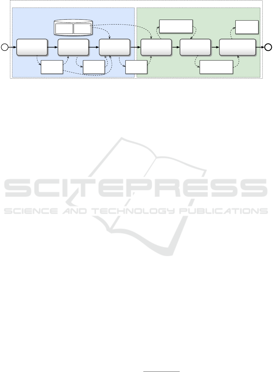
Figure 1: Overview of the Method Development process.
ing process whose activities are split into two main
disciplines: Method Development and Method Enact-
ment. Besides the Method Engineering Process, an-
other integral part of the solution approach is Method
Base. The Method Base contains the building blocks,
Method Fragments (Jovanovikj et al., 2018), and
Method Patterns (Jovanovikj et al., 2020c), needed
for assembling the test migration method. By per-
forming activities of the Method Development dis-
cipline, a situation-specific test method gets devel-
oped. It comprises Situational Context Identification
and Transformation Method Construction. During
Situational Context Identification, the situational con-
text is analyzed and characterized by both system and
test migration perspectives. Firstly, in the Concept
Identification activity, both the source and the target
tests and system are represented as a set of concepts
by applying concept modeling. Then, based on this
concept representation in terms of a Concept Model,
the impact of the system changes on the test cases is
identified and captured in terms of an Impact Model
in the Co-Evolution Analysis activity. Lastly, as part
of the Influence Factor Identification activity, the in-
fluence factors are identified. Having the context in-
formation collected in terms of a Situational Context
Model, the Method Construction activity can be ini-
tiated and a situation-specific test migration method
gets constructed. The overall outcome of Method De-
velopment is a Transformation Method Specification
which defines how to perform the migration by defin-
ing the activities to be executed and the artifacts that
should be generated. If each step previously intro-
duced process requires manual work, it would result
in a lot of time and effort. All in all, the development
and enactment of test transformation methods with-
out proper tool support and guidance could lead to
quite complex manual work and consequently would
require a lot of time.
To support the previously introduced solution, we
implemented a modeling workbench using Eclipse
Sirius. The modeling workbench supports the mod-
ular construction of context-specific, model-driven
migration methods for test case co-migration (Jo-
vanovikj et al., 2019). As the method development
process consists of situational context identification
and transformation method construction phases, cor-
respondingly, appropriate modeling layers were de-
fined in the modeling workbench phase. To demon-
strate the applicability of the developed framework in
practice, we performed a feasibility study in which
parts of the well-known Eclipse Modeling Frame-
work (EMF) along with the Object Constraint Lan-
guage (OCL) were migrated to the multi-platform en-
abled modeling framework CrossEcore. The feasibil-
ity studies addressed two different languages in the
target environment, namely C# and TypeScript, and
consequently two different target testing frameworks,
NUnit and Jasmine. Due to the space constraint, only
the migration to NUnit is elaborated in the paper. Ad-
ditionally, scientific interviews were conducted with
experts in the area of software migration and software
testing to assess the benefit of the provided tool.
2 MODELING WORKBENCH:
OVERVIEW
The modeling workbench
1
for the development of sit-
uational test case co-migration methods is developed
using Eclipse Sirius. In general, there are mainly
three steps to creating a modeling tool. Firstly, the
metamodel definitions have to be provided by using
EMF and Ecore. Secondly, a model definition is de-
fined and this is done in a new run-time environ-
ment in Eclipse whereafter a modeling project is cre-
ated. At this point, we refer to the metamodel defini-
tion created in the first step and select the appropri-
ate model that we want to create. Finally, the mod-
1
https://github.com/xmefisto/xmefisto
A Modeling Workbench for the Development of Situation-specific Test Co-migration Methods
233
Modeling Workbench
Viewpoint
Table
Description
Diagram
Description
Concept
Layer
Integrated
Test Horseshoe
Layer
Influence Factor
Line Element
Metamodel
Definition
Model
Definition
Impact
Layer
Influence Factor
Layer
Test Horseshoe
Layer
Transformation
Method Construction
Components
Situational
Context Identification
Components
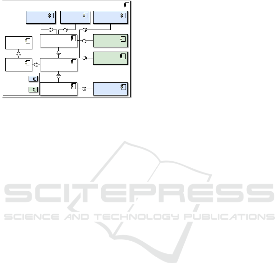
Figure 2: Overview of Modeling Workbench Architecture.
eling workbench definitions are defined by creating
a Viewpoint Specification Project. Figure 2 presents
an overview of the modeling workbench architecture.
On the left, the metamodel and the model are depicted
which are the basis for the creation of the different
layers in the modeling workbench. The metamodel
addresses all the previously introduced artifacts in the
process overview shown in Figure 1. Then, based on
the specified metamodel and model, a central View-
point is defined which in turn contains all the sup-
ported representations of various modules that are
supported by the framework. Two parts in this view-
point are vital to support the construction of all the
necessary models in the Method Development phase
namely, Diagram Description and Table Description.
In general, the modeling workbench has com-
ponents that comprise two modules, the Situational
Context Identification module and the Transformation
Method Construction module. These support the cor-
responding steps of the method development process
shown in Figure 1. Models can be represented either
in graphical representation or tabular representation,
as shown with the components Diagram Descrip-
tion and Table Description respectively. We support
graphical views for Concept Model, Impact Model,
Influence Factor Model, Fragmented Transformation
Method Specification, and Integrated Transformation
Method Specification. The corresponding artifact def-
initions are defined in the Concept Layer, Impact
Layer, Influence Factor Layer, Test Horseshoe Layer,
and Integrated Test Horseshoe Layer. The Influence
Factor Model has a tabular representation and the cor-
responding artifact definition is provided by the Influ-
ence Factor Line Element component.
As part of the feasibility study, we migrated test
cases of the well-known Eclipse Modeling Frame-
work (EMF) into a new environment by using our
framework. EMF is highly adopted in practice which
can generate source code from platform-independent
models with embedded Object Constraint Language
(OCL) expressions. Nowadays, more and more appli-
cations target multiple platforms like Windows, ma-
cOS, web browsers, or mobile platforms like Android
or iOS, which means that they need to be imple-
mented in different programming languages. How-
ever, since its introduction in 2003, EMF is focused
solely on Java as a target language. Hence, no feature-
complete Ecore and OCL runtime APIs are available
for all the platforms implying that their functionality
has to be re-implemented. CrossEcore (Schwichten-
berg et al., 2018) overcomes this problem by provid-
ing code-generation of platform-specific code from
platform-independent Ecore models with associated
OCL expressions. The OCL compiler, which is a part
of the CrossEcore Code Generator, transcompiles the
string-based OCL expressions into expressions of the
target programming language. Hence, the OCL ex-
pressions are translated at design-time and ahead of
compilation, i.e., in Ahead-Of-Time (AOT) manner.
As EMF’s OCL implementation is well tested and
over 4000 JUnit test cases are available on public code
repositories, their reuse is a viable example to demon-
strate our modeling workbench. It has to be noted that
CrossEcore’s OCL implementation is entirely differ-
ent when compared to EMF’s OCL implementation.
EMF supports the generation of Java code, whereas
CrossEcore provides support for multiple platforms
or multiple programming languages.
3 SITUATIONAL CONTEXT
IDENTIFICATION
To support the Situational Context Identification part
of the process, we provide graphical representations
for the three models (Concept Model, the Impact
Model, and the Influence Factor Model) by provid-
ing the Diagram Description component for each of
them. Additionally, a tabular representation for the
Influence Factor Model which is implemented using
the Table Description component is provided. Fig-
ure 3 shows the graphical modeling editor along with
an example of a Situational Context Model and the
palette which consists of different elements that are
necessary to create the models. Furthermore, differ-
ent layers can be shown by selecting the appropriate
layers from the layers dropdown.
Concept Model Artifact Definitions. The Concept
Layer defines all the necessary artifact definitions that
are needed to create the Concept model. For creat-
ing a concept model, one can drag and drop concerns,
MODELSWARD 2021 - 9th International Conference on Model-Driven Engineering and Software Development
234
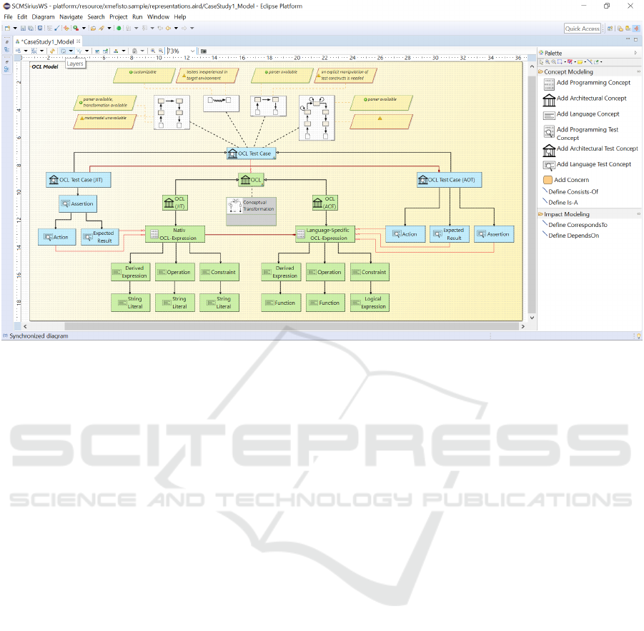
Figure 3: Overview of Situational Context Identification Modeling Workbench.
system concepts, and test concepts from the Concept
Modeling section in the Palette seen on the right side
in Figure 3. Furthermore, Consists-Of or Is-A re-
lationships between the system concepts or between
the test concepts can be defined by using the connect-
ing edges from the palette. The modeling tool also
supports the specification of different types of con-
cepts like Original Test Concept, Shared Test Con-
cept, or a Target Test Concept using the properties tab.
Based on the OCL constraints in the metamodel, the
tool restricts the Consists-Of and Is-A edge creation
by restricting the appropriate source and target con-
cepts. Additionally, the tool supports specifying the
system method pattern used for system migration in
the Concept Model by choosing an appropriate sys-
tem method pattern. To show the feasibility, we re-
fer again to the case study. The test framework for
the source test environment is the JUnit framework
and the target test environment is the NUnit frame-
work. Along with the original, shared, and target sys-
tem and test concepts as shown in Figure 3, we also
identify the applied system method pattern for OCL
shared system concept as a Conceptual Transforma-
tion.
Impact Model Artifact Definitions. The Impact
Layer defines all the necessary artifact definitions that
are needed to create the Impact model. The Impact
Model is an extension to the Concept Model with ad-
ditional information on how the system migration and
test case migration is related at a concept level. To
define the Impact Model, select the impact layer from
the dropdown so that the ’Impact Modeling’ section
will be visible in the Palette. Relationships for the
Impact Model can be defined using the Correspond-
sTo and DependsOn edges from the ’Impact Model-
ing’ section in the Palette. The Impact Model is cre-
ated by adding the co-evolution relationships to the
Concept Model. To specify the co-evolution depen-
dencies, two relationship types are, namely Corre-
spondsTo and DependsOn. A dependency between
a test concept and a system concept is represented
by the DependsOn relation. A correspondence be-
tween a source and a target concept is represented by
the CorrespondsTo relation. As the underlying meta-
model definition is created by adding the necessary
OCL constraints, those constraints are also applica-
ble in the modeling workbench. In addition to spec-
ifying the co-evolution relationships and defining the
impact set, the correspondence relation specific to a
system concept or a test concept can also be specified
in the properties window. As part of the Co-evolution
Analysis, the relationship between the test concepts
and system concepts is specified in the form of an Im-
pact Model. An Impact Model represents how the sys-
tem changes influence the test case co-migration in a
meaningful way using the provided modeling work-
bench which relies on the corresponding metamodel
definition as shown in Figure 3.
Influence Factor Model Artifact Definitions. The
Influence Factor Layer defines all the necessary arti-
A Modeling Workbench for the Development of Situation-specific Test Co-migration Methods
235

fact definitions that are needed to create the graph-
ical representation of the Influence Factor model.
Whereas, the Influence Factor Line Element defines
all the necessary artifact definitions that are needed
to define the modeling workbench to create the tabu-
lar representation of the Influence Factor model. Test
influence factors are defined by creating a tabular In-
fluence Factor Model specific to a shared test concept
and by listing all the suitable test method patterns that
are under consideration. Furthermore, the influence
factors can shown also graphically by selecting the
Suitable Method Patterns and Influence Factors lay-
ers from the layers dropdown as shown in Figure 3.
Finally, as part of Influence Factor Identification, the
factors that influence the test case migration are iden-
tified and the advantages and disadvantages of each of
the test influence factors specific to each of the suit-
able test method pattern are summarized. For this pur-
pose, the modeling workbench provides test-related
elements.
4 TRANSFORMATION METHOD
CONSTRUCTION
Based on the constructed Situational Context Model,
a transformation method is specified. Firstly, in
Method Pattern Selection and Configuration, a test
method pattern for each identified test concept is se-
lected, from the list of Suitable Test Method Patterns,
and configured. The output is a Fragmented Transfor-
mation Method Specification which comprises a set
of test horseshoe models, each of which represents
a transformation strategy for the associated test con-
cept. During Method Pattern Integration, the differ-
ent horseshoe models in the Fragmented Transforma-
tion Method Specification are integrated by defining
relationships between their method fragments on the
Integrated Test Horseshoe Layer. The output is an In-
tegrated Transformation Method Specification. The
final step, Instantiation of Tool Implementation Phase
Fragments, focuses on the preparation to instantiate
the tools that are required for performing the actual
transformation, as identified in the Integrated Trans-
formation Method Specification. The final output is
the Transformation Method Specification.
Method Pattern Selection and Configuration Arti-
fact Definitions. As seen from Figure 3, the possi-
ble test method pattern candidates for the test con-
cept, OCL Test Case, have been identified. Each
test method pattern is evaluated based on the iden-
tified influence factors. Among these, the most suit-
able candidate in terms of effectiveness and efficiency
has to be chosen. For this example, Test Language-
based Test Transformation is chosen as the viable
candidate for transforming the OCL Test Case con-
cept. Once a pattern is selected, a Test Transformation
Method Specification gets automatically instantiated
which includes the selected method pattern. The next
step is a coarse-granular configuration of the spec-
ification, where the selected method pattern can be
configured to include optional parts. For example, if
an enrichment has to be performed on the Model of
Original Executable Tests (MOET), then such a con-
figuration activity can be specified in the applied test
method pattern, which in this case is Test Language-
based Test Transformation. This kind of coarse gran-
ular configuration can be done by specifying it in the
Test Method Pattern Configuration associated with
the selected pattern. Next, customized method frag-
ments are derived which serve as placeholders for
the fine-granular configuration of the selected method
pattern. The actual specification is specified using a
Test Horseshoe Model editor (Figure 4). The editor
provides options to add inner fragments within outer
fragments and define relations between them. For
instance, Extract Expected Results, Extract Actions
and Discover Assertions are inner fragments of the
outer fragment Test Case Understanding. Control and
data flow can be specified between various fragments.
Among the OCL test cases, there exists also some
regression tests which cannot be transformed auto-
matically as they have an irregular structure. Conse-
quently, a different test horseshoe model correspond-
ing to the Test Reimplementation pattern is created for
the same. The set of these two horseshoe models, i.e.,
Test Langauge-based Test Transformation pattern and
Test Reimplementation pattern form the Fragmented
Transformation Method Specification.
Method Pattern Integration Artifact Definitions.
As part of Method Pattern Integration, different test
horseshoe models are combined in the Fragmented
Transformation Method Specification. For this, we
have defined an Integrated Test Horseshoe Model ed-
itor on the Integrated Test Horseshoe Layer. Using an
Integrated Test Horseshoe Model editor, different test
horseshoe models corresponding to the same or dif-
ferent test method patterns can be selected and initial-
ized into the editor. This provides a better view as it
includes information about the transformation of mul-
tiple test concepts identified in the Situational Con-
text Model. The Integrated Transformation Method
Specification for this feasibility study which com-
bines the Test Language-based Test Transformation
and Test Reimplementation horseshoe models avail-
able in the Fragmented Transformation Method Spec-
MODELSWARD 2021 - 9th International Conference on Model-Driven Engineering and Software Development
236
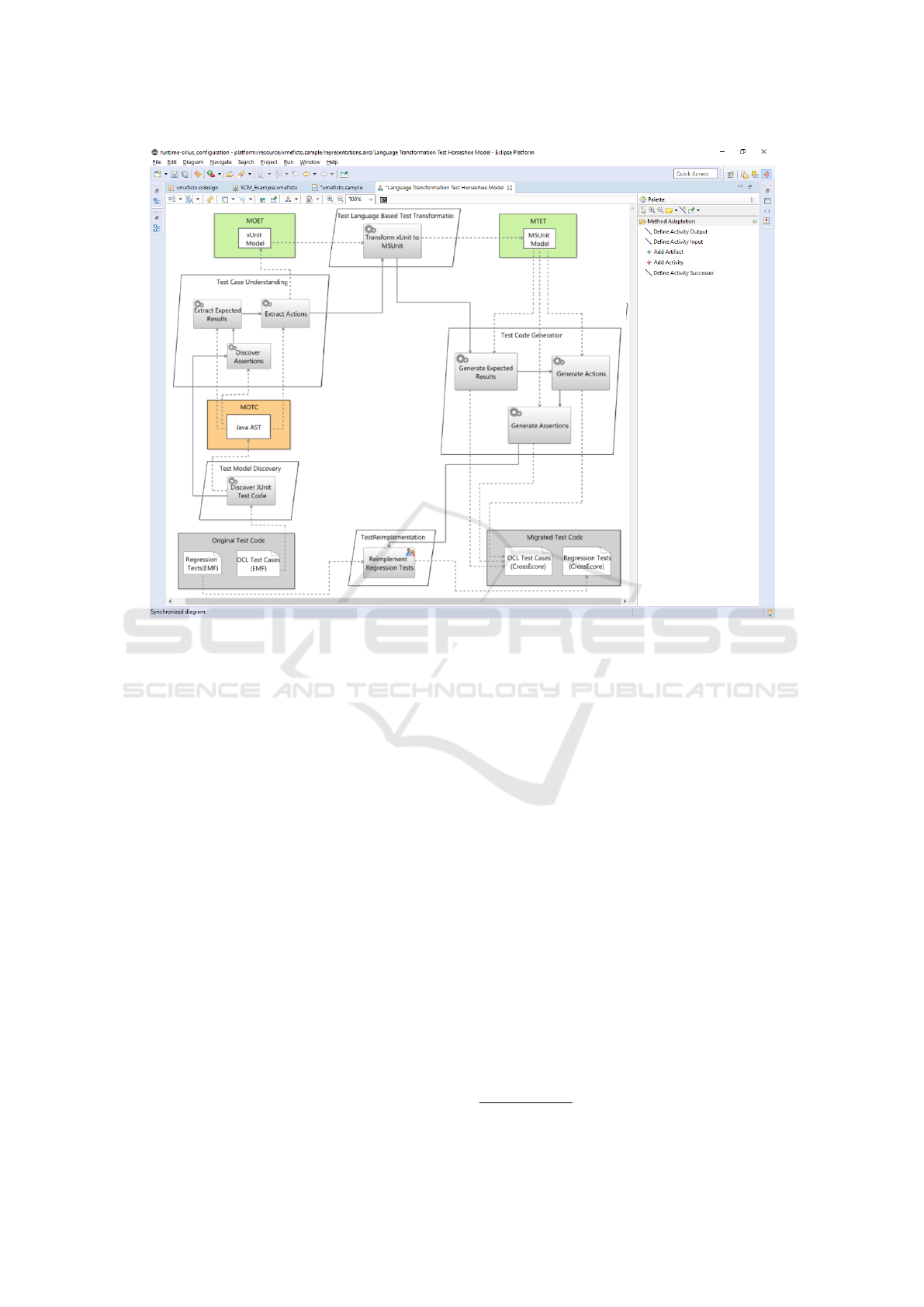
Figure 4: Overview of Transformation Method Construction Modeling Workbench.
ification can be seen in Figure 4. The Instantiation
of Tool Implementation Phase Fragments is the last
step that results in the final Transformation Method
Specification. Here, the tools that are required for per-
forming the actual transformation are prepared. Even
though we have not yet provided an explicit editor to
model the Tool Implementation phase, there is an op-
tion to specify them as Preparation Phase Test Frag-
ments.
5 EVALUATION
To analyze the benefit of the usage of the modeling
workbench, an evaluation was performed by conduct-
ing interviews with seven domain experts. We pre-
sented the tool to test managers, senior developers,
and senior researchers from different companies and
research institutes and collected their feedback. The
main goal was to get feedback on the usability, effi-
ciency, effectiveness, generality, and completeness of
the framework and modeling workbench. For eval-
uating the usability factor, System Usability Scale
(SUS) (Drew et al., 2018) questionnaire was used.
Furthermore, a set of ten questions specific to Sit-
uational Context Identification and Transformation
Method Construction were also asked. Due to the cur-
rent situation with the Corona Virus, the expert inter-
views were conducted via Skype. Firstly, we prepared
a video presentation
2
for about ten minutes. After the
video presentation, a discussion was conducted with
the experts followed by collecting their suggestions
and feedback. Each of the experts was requested to
answer a set of twenty questions, ten SUS questions to
measure the usability of our tool (Bangor et al., 2008)
and ten approach-specific questions. SUS was used
even though it was not a classic usability experiment
and it still was very useful for us because it helped
us in getting an insight from the expert perspective
and we could identify the areas that we could improve
upon. In the end, the additional learnings and sugges-
tions were also noted. We got a SUS score of 58.93
(Figure 5) for the modeling workbench support to cre-
ate the Situational Context Model which was consid-
ered acceptable. For the modeling workbench sup-
port to create the Test Horseshoe Model and the In-
tegrated Test Horseshoe Model, we got a SUS score
of 62.14 which was also considered acceptable. In
both cases, for question 5 as shown in Figure 5, all
2
https://bit.ly/2IWYa3u
A Modeling Workbench for the Development of Situation-specific Test Co-migration Methods
237
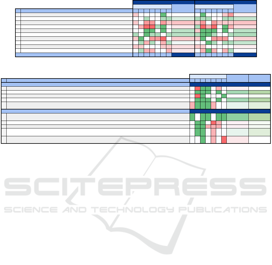
# Survey Question A B C D E F G A B C D E F G
1 I think that I would like to use this system frequently. 3 4 4 4 4 5 4 4,00 4 5 4 4 4 3 2 3,71
2 I found the system unnecessarily complex. 3 3 2 3 3 2 2 2,57 2 2 2 3 3 2 2 2,29
3 I thought the system was easy to use. 3 4 2 2 4 2 3 2,86 3 2 4 2 3 3 3 2,86
4 I think that I need the support of a tech. person to use this system. 3 4 5 5 2 1 3 3,29 2 5 4 5 3 1 4 3,43
5 I found the various functions in this system were well integrated. 4 4 5 5 4 5 4 4,43 3 5 5 5 4 5 4 4,43
6 I thought there was too much inconsistency in this system. 2 3 1 2 2 3 2 2,14 2 1 1 2 3 3 2 2,00
7 I would imagine that most people would learn to use this system very quickly. 3 5 4 2 2 1 4 3,00 3 5 4 2 2 2 4 3,14
8 I found the system very cumbersome to use. 3 2 4 2 3 4 2 2,86 3 3 1 2 3 2 2 2,29
9 I felt very confident using the system. 3 3 4 4 4 3 3 3,43 3 3 4 4 4 4 4 3,71
10 I needed to learn a lot of things before I could get going with this system. 3 2 4 4 3 3 4 3,29 3 4 1 4 3 4 2 3,00
55 65 58 53 63 58 63 58,93 60 63 80 53 55 63 63 62,14
Situational Context Identification
Transformation Method Construction
Average Value
Average Value
Response by participant
SUS Score:
Response by participant
Figure 5: SUS Questionnaire Results (green - higher agreement, red - higher disagreement).
# A B C D E F G
1 4 2 5 5 4 3 4 3,86 71,43
2 4 5 5 5 4 5 4 4,57 89,29
3 4 2 5 4 4 4 5 4,00 75,00
4 4 5 5 5 4 5 4 4,57 89,29
5 3 5 5 5 3 4 4 4,14 78,57
1 5 4 5 5 4 5 5 4,71 92,86
2 4 5 5 4 2 3 4 3,86 71,43
3 4 5 5 3 3 3 4 3,86 71,43
4 4 5 5 4 3 4 4 4,14 78,57
5 4 4 5 4 3 4 2 3,71 67,86
The notion of co-migration patterns helps in making better informed decisions while migrating the test cases of a system which has
already been migrated.
The contents of the xMEFiSTo method base provide sufficient control while developing a transformation method for test cases.
I believe that the defined process can be used for specifying test concepts for different test environments.
I would imagine that the final Situational Context Model gives a clear picture of the context and thus it is effective in selecting the
appropriate test method pattern.
I found that the models created using the tool are easy to understand.
I think it is meaningful to identify the dependencies at a concept level.
The identification of the dependencies in co-evolution analysis step should be automated, e.g., by code dependency analysis.
The contents of the xMEFiSTo method base provide sufficient flexibility while developing a transformation method for test cases.
The process defined is general enough ,i.e, it is not restricted to any specific environment and can be used for specifying
transformation methods for different environments.
The Test Transformation Method Specification obtained at the end of the Method Development process covers all the aspects
required for enacting the actual transformation of test code.
Percentage
SCI
TMC
Survey Question
Response by participant
Average Value
Figure 6: Model and Tool Specific Questionnaire Results (green - higher agreement, red - higher disagreement).
the experts agreed that the various functions in this
system were well integrated. But, as we conducted
the usability evaluation using a presentation, we got
an unfavorable score for questions 3, 7, and 10. We
believe that if the users were allowed to use the sys-
tem and to explore the tool, we would have got a bet-
ter SUS score. Regarding Situational Context Iden-
tification, the experts agreed that it is meaningful to
identify the dependencies at a concept level and the
models were easy to understand except for the sec-
ond expert who was not familiar with modeling tools
(Figure 6). The process followed in identifying the
concepts, dependencies, and influence factors were
considered efficient and the final Situational Context
Model is effective because it gives a clear picture of
the context and helps in selecting the appropriate test
method pattern specific to the shared test concept. In
general, the experts had the opinion that the identifi-
cation of the dependencies in the co-evolution analy-
sis step should be automated but as seen in Figure 6,
the second expert had the opinion that it should not be
considered if the cost of automating exceeds the cost
of doing it manually. The experts suggested that the
defined process can be used for specifying test con-
cepts for different test environments thus it satisfied
the generality aspect to an extent. Based on the feasi-
bility study presented, the experts evaluated the Situ-
ational Context Model to be complete because all the
necessary elements could be created with the help of
the provided modeling workbench. However, com-
pleteness cannot be measured with just one feasibility
study. Regarding Transformation Method Construc-
tion (bottom half of Figure 6), the experts felt that
the notion of co-migration patterns provides guidance
to reuse existing artifacts and tools from system mi-
gration and thereby eases the selection and configu-
ration of a test method pattern. A moderately high
score was given for the conditions of control and flex-
ibility as they felt that a sufficient degree of control
and flexibility in the process is provided through the
test method patterns and test method fragments. The
last question regarding the completeness of the trans-
formation method specification has a relatively lower
score since the system was not used directly by the
experts.
6 RELATED WORK
The method engineering approaches provide modular
construction of a method. It relies on a set of prede-
fined building blocks for methods and a method en-
gineering process that guides the method construc-
tion. A method engineering approach that enables
modular construction is presented in (Khadka et al.,
2011), but is specific for migration to service-oriented
environments. MEFiSTo (Grieger, 2016) overcomes
this by providing a framework for the construction of
situation-specific system migration methods and also
a modeling workbench, developed using Eclipse Sir-
ius. This modeling workbench can be used to model
various elements related to the method development
MODELSWARD 2021 - 9th International Conference on Model-Driven Engineering and Software Development
238

process for system migration, but it does not include
any elements that can be used to model a test case
migration scenario. ARTIST (Menychtas and et al.,
2014) advocates an approach that provides support
for the migration of test cases to some extent, namely
the consideration of the test context, as well as the
analysis of the impact that the system changes have
on the test cases. In (Mirzaaghaei et al., 2012), a
semi-automatic approach is presented that supports
test suite evolution through test case adaptations. Ex-
isting test cases are repaired and new test cases are
generated to react to incremental changes in the soft-
ware system. In (Rapos, 2015), a method is proposed
which should improve the model-based test efficiency
by co-evolving test models. In this work, the effects
of software evolution models on test models are stud-
ied so that updates can be applied directly to tests.
None of these approaches provide tool support for
modeling test case co-migration methods.
7 CONCLUSION AND FUTURE
WORK
In this paper, we presented a modeling workbench
that enables a modular construction of context-
specific, model-driven migration methods for test
case migration. The method development process
consists of situational context identification and trans-
formation method construction. Correspondingly, ap-
propriate modeling layers were defined in the mod-
eling workbench for each step in the method devel-
opment process. Evaluation of our tool was done by
conducting a feasibility study and by conducting sci-
entific interviews with experts in the field of software
migration. Full or partial automation of co-evolution
analysis is one possible direction for future work. Fur-
thermore, it can be helpful to provide distinct views
on different parts of the system, as the models in the
industrial test case migrations can be quite large. In
recent work (Jovanovikj et al., 2020a), mutation anal-
ysis was suggested as a validation technique for test
case migration. Creating such validation methods can
be also supported in a future extension.
REFERENCES
Bangor, A., Kortum, P. T., and Miller, J. T. (2008). An
empirical evaluation of the system usability scale. Int.
J. Hum. Comput. Interact., 24(6):574–594.
Drew, M. R., Falcone, B., and Baccus, W. L. (2018). What
does the system usability scale (SUS) measure? - val-
idation using think aloud verbalization and behavioral
metrics. In Marcus, A. and Wang, W., editors, Design,
User Experience, and Usability: Theory and Practice
- 7th International Conference, 2018.
Grieger, M. (2016). Model-Driven Software Modern-
ization: Concept-Based Engineering of Situation-
Specific Methods. PhD thesis, Paderborn University.
Henderson-Sellers, B., Ralyt
´
e, J.,
˚
Agerfalk, P. J., and Rossi,
M. (2014). Situational Method Engineering. Springer.
Jovanovikj, I., Engels, G., Anjorin, A., and Sauer, S.
(2018). Model-driven test case migration: The test
case reengineering horseshoe model. In Informa-
tion Systems in the Big Data Era - CAiSE Forum
2018, Tallinn, Estonia, June 11-15, 2018, Proceed-
ings, pages 133–147.
Jovanovikj, I., Yigitbas, E., Grieger, M., Sauer, S., and
Engels, G. (2019). Modular construction of context-
specific test case migration methods. In Proceedings
of the 7th International Conference on Model-Driven
Engineering and Software Development, MODEL-
SWARD 2019, 2019., pages 534–541.
Jovanovikj, I., Yigitbas, E., Nagaraj, A., Anjorin, A., Sauer,
S., and Engels, G. (2020a). Validating test case mi-
gration via mutation analysis. In AST@ICSE 2020:
IEEE/ACM 1st International Conference on Automa-
tion of Software Test, 2020, pages 31–40. ACM.
Jovanovikj, I., Yigitbas, E., Sauer, S., and Engels, G.
(2020b). Concept-based co-migration of test cases.
In Hammoudi, S., Pires, L. F., and Selic, B., edi-
tors, Proceedings of the 8th International Conference
on Model-Driven Engineering and Software Develop-
ment, MODELSWARD 2020, 2020, pages 449–456.
SCITEPRESS.
Jovanovikj, I., Yigitbas, E., Sauer, S., and Engels, G.
(2020c). Test case co-migration method patterns. In
Combined Proceedings of the Workshops at Software
Engineering 2020 Co-located with the German Soft-
ware Engineering Conference 2020 (SE 2020),2020.
Khadka, R., Reijnders, G., Saeidi, A., Jansen, S., and Hage,
J. (2011). A method engineering based legacy to soa
migration method. pages 163–172.
Mens, T. and Demeyer, S., editors (2008). Software Evolu-
tion. Springer.
Menychtas, A. and et al. (2014). Software modernization
and cloudification using the artist migration method-
ology and framework. Scalable Computing: Practice
and Experience, 15:131–152.
Mirzaaghaei, M., Pastore, F., and Pezz
`
e, M. (2012). Sup-
porting test suite evolution through test case adapta-
tion. Proceedings - IEEE 5th International Confer-
ence on Software Testing, Verification and Validation,
ICST 2012.
Rapos, E. J. (2015). Co-evolution of model-based tests for
industrial automotive software. In 2015 IEEE 8th In-
ternational Conference on Software Testing, Verifica-
tion and Validation (ICST), pages 1–2.
Schwichtenberg, S., Jovanovikj, I., Gerth, C., and Engels,
G. (2018). Poster: Crossecore: An extendible frame-
work to use ecore and ocl across platforms. In Poster:
CrossEcore: An Extendible Framework to Use Ecore
and OCL across Platforms.
A Modeling Workbench for the Development of Situation-specific Test Co-migration Methods
239
