
Interfacing Digital and Analog Models for Fast Simulation and Virtual
Prototyping
Daniela Genius
1
and Ludovic Apvrille
2
1
Sorbonne Université, LIP6, CNRS UMR 7606, Paris, France
2
LTCI, Télécom, Université Paris-Saclay, Paris, France
Keywords:
System-level Design, Virtual Prototyping, Cyber-physical Systems, Co-simulation.
Abstract:
The paper presents an enhancement for the virtual simulation of analog/mixed-signal systems from high-level
SysML models. Embedded systems, e.g. in robotic systems, feature both digital and analog circuits such as
sensors and actuators. Simulation of these system requires to handle both domains (digital, analog); our aim
is thus to make the interactions between these two domains explicit. For this, the paper first defines new send
and receive procedures, then explains how to check semantic aspects of models to ensure a correct simulation.
A running example illustrates the basic concepts of our approach. A proof of concept based on an existing
rover is also presented.
1 INTRODUCTION
Model-driven techniques have been proposed for de-
signing both software and hardware aspects of digital
platforms. High level models are employed to spec-
ify the functionality of the system, and subsequent
model transformations are applied until a virtual pro-
totype containing software and hardware can be gen-
erated. However, embedded systems —e.g. robotics,
automotive and medical systems— are frequently
built upon heterogeneous hardware components such
as processors, FPGAs, DSPs, hardware accelerators,
digital and analog analog/mixed signal (AMS) and
radio frequency (RF) circuits. We focus on embed-
ded systems running on (multi-processor) Systems-
on-Chip, containing application software, operating
systems and hardware. Yet, it is impossible to ob-
tain simulation results close enough to reality without
using different Models of Computation (MoCs): one
for the digital part, and one for the analog part. A
difficulty is then to associate the two MoCs. Finding
the right level of abstraction to do this is an important
factor that strongly impacts the relevance of simula-
tion results.
TTool (Apvrille et al., 2020) already captures soft-
ware with a SysML-like notation (blocks, state ma-
chines), formally verifies these models and generates
C code running on a digital virtual prototype. This
generation is expected to produce correct by construc-
tion code, unless user-defined code is inserted in state
machines (entry code or custom methods).
We focus on the link between the analog and digi-
tal MoCs, already discussed in (Genius et al., 2019a).
Our contribution relies on adding new SysML blocks
and state machine operators in order to model links
between analog and digital domains, and integrate
these new aspects into a SysML-like notation. More-
over, from this notation, the paper proposes a model-
to-virtual-prototype transformation combining Sys-
temC and SystemC-AMS in order to evaluate the sys-
tem under design. The paper shows the semantic is-
sues and ways to handle them. As a result, we pro-
vide a better integration of analog design within the
SysML (digital) world.
The next section gives an overview of existing ap-
proaches targeting the modeling and/or co-simulation
of cyber-physical systems. Section 3 presents the ba-
sic concepts behind the simulation of analog compo-
nents. Section 4 explains how digital and analog com-
ponents can be modeled and evaluated together. Sec-
tion 5 presents a rover case study. Finally, section 6
concludes the paper and draws perspectives.
2 RELATED WORK
Embedded Systems have strict performance and real-
time constraints; they often run on (very) limited re-
sources. UML defines extension mechanisms called
profiles to e.g., define new operators, provide their se-
mantics and supply a methodology. UML profiles are
defined either by OMG (e.g. MARTE (Vidal et al.,
2009), and SysML (Friedenthal et al., 2014) or by tool
224
Genius, D. and Apvrille, L.
Interfacing Digital and Analog Models for Fast Simulation and Virtual Prototyping.
DOI: 10.5220/0010257202240231
In Proceedings of the 9th International Conference on Model-Driven Engineering and Software Development (MODELSWARD 2021), pages 224-231
ISBN: 978-989-758-487-9
Copyright
c
2021 by SCITEPRESS – Science and Technology Publications, Lda. All rights reserved

vendors (e.g. in Rhapsody, Artisan).
2.1 SysML
System engineers have an approach which is differ-
ent from the one preferred by software designers in
many ways; in particular they need to express al-
location relations, which are not well supported in
UML
1
. SysML is a UML 2 profile developed by the
Object Management Group (OMG) and the Interna-
tional Council on Systems Engineering (INCOSE).
It is a graphical modeling language that supports the
specification, analysis, design, verification, and vali-
dation of systems that include hardware and software,
but also data, staff, procedures, and facilities. Pro-
prietary tools like Enterprise Architecture (Lankhorst
et al., 2009), Rhapsody(Schinz et al., 2004) and free
software tools like Polarsys(Blondelle et al., 2015),
Papyrus (Lanusse et al., 2009), and TTool (Apvrille
et al., 2020), support SysML.
UML/SysML based modeling techniques are far
less widely used for heterogeneous system design
(Selic and Gérard, 2013). With few exceptions (Taha
et al., 2010; Li et al., 2018), they do not support re-
finement until cycle/bit accurate level virtual proto-
types nor provide OS support for full-system simu-
lation. Co-simulation between different Models of
Computation is usually not addressed.
2.2 Analog/Mixed Signal Design
Several well established tools in analog/mixed sig-
nal design, like Ptolemy II (Lee, 2010) (Ptolemy.org,
2014), are based upon a data-flow model. They target
heterogeneous system design by defining several sub
domains and using hierarchical models. Yet, the In-
stantiation of elements controlling time synchroniza-
tion between domains is left to designers.
Metro II (Davare et al., 2007) introduces hierarchy
and allows so-called Adaptors for data synchroniza-
tion, which serve as a bridge between the semantics of
components belonging to different Models of Compu-
tation (MoCs). Model designers still have to imple-
ment time synchronization by means of constraints,
assertions, annotators and schedulers. As a common
simulation kernel handles the entire process execution
(digital and analog), MoCs are not well separated.
Discrete Event System Specification (DEVS
(Concepcion and Zeigler, 1988)) is a modular and hi-
erarchical formalism for modeling and analyzing gen-
eral systems. DEVS supports discrete events and con-
tinuous systems described by differential equations,
1
UML supports deployment diagram in which artifacts
can be associated to nodes.
or hybrid systems. A dozen of platform implemen-
tations based on DEVS exist, ranging from Petri Net
over object oriented to Python based.
Modelica (Fritzson and Engelson, 1998) is an
object-oriented modeling language for component-
oriented systems containing e.g. mechanical, elec-
trical, electronic and hydraulic components. Classes
contain a set of equations that can be translated into
objects running on a simulation engine. Yet, since
time synchronization is not predefined, the simulation
engine must manipulate objects in a symbolic way in
order to determine an execution order between com-
ponents of different MoCs.
Several frameworks for modeling digital hardware
are based on SystemC (IEEE, 2011), a library of C++
classes. SystemC AMS extensions based on Sys-
temC is about to become a standard within the ana-
log/mixed signal hardware design domain (Vachoux
et al., 2003). None of these approaches provide a
high-level, graphical interface for specifying the ap-
plication.
3 BASIC CONCEPTS
Our approach targets the interaction between two sim-
ulation semantics related to two different models of
computation, and make them comprehensible from
the software design point of view. For the digital
part of the system, we model embedded software in a
SysML-like manner; the hardware is modeled in Sys-
temC, running a minimal operating system (Becoulet,
2010). For the digital part of the system, a Discrete
Event (DE) MoC is employed. For the analog part,
a model derived from static data-flow, named Timed
Data Flow (TDF), is used. Our aim is to make the in-
teractions between these two MoCs explicit by defin-
ing send and receive operators to be used in the state
machines. We also intend to represent the results of
simulation with sequence diagrams.
3.1 SysML Representation
Generally speaking, TTool, our framework, supports
most SysML diagrams: requirement diagrams, use
case diagrams, sequence diagrams and activity dia-
grams for analysis, block definition diagrams, inter-
nal block diagrams and state machines diagrams for
design. Our present contribution focuses on design di-
agrams. TTool slightly extends OMG-based SysML:
our block diagram merges block and internal block di-
agrams, modifies SysML parametric diagrams to ex-
press properties, but do not support continuous flows.
Interfacing Digital and Analog Models for Fast Simulation and Virtual Prototyping
225
Block diagrams define blocks and their intercon-
nection; their behavior is expressed with State Ma-
chine Diagram, one per block. We give a formal
semantics to block and state machine diagrams as a
starting point for simulation, verification and code
generation. Ports are connected to allow the state ma-
chines corresponding to each block to exchange sig-
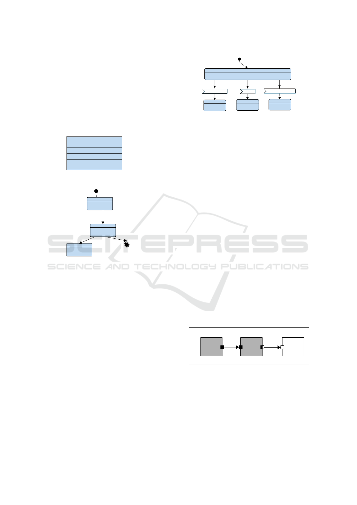
nals. Figure 1 shows a block diagram consisting of a
single block with one attribute, one method and one
signal.
Block stereotype
instance name
Methods
Attributes
Signals
<<block>>
Block0
- data : int;
- method1()
~ out output(int data)
Figure 1: Block.
after (10, 20)
state0
state1
Initial state
State
state2
Final state
Figure 2: State Machine Diagram.
State machine diagrams are composed of states and
transitions, as shown in Figure 2. A transition is trig-
gered by an action (signal reception, signal sending,
setting of attributes) if all its conditions are resolved
(guard, timing constraint).
SysML State Machines are enhanced with delays:
after(tmin , tmax ) models a non deterministic delay
during which a block is suspended.Also, receiving or
sending a message is made explicit.
An asynchronous communication is FIFO-based,
i.e. a reader can fire the transition leading to a read-
ing operation only if if size(FIFO) > 0. FIFO com-
munication is always blocking for the reader but can
be blocking or non-blocking for the writer. In a
synchronous communication, the reading and writing
transitions are fired simultaneously whenever a ren-
dezvous is possible.
From the same state, it is possible to wait for sev-
eral signals (see Figure 3). For an asynchronous com-
munication, the first signal in the input queues triggers
the transition, for a synchronous communication, the
first ready-to-execute rendezvous triggers the transi-
tion. The others are discarded.
STATE2
STATE3
STATE1
WAIT
signal1(number)
signal2()
signal3(number, flag)
Figure 3: Multiple signal reception from one state. Only
one signal reception is executed among the possible ones.
Functional simulation generates a random execution
trace depicted as a sequence diagram. A reachability
graph shows all possible situations. Model-checking
can directly be performed on the model, i.e. without
generating an intermediate formal specification. Ad-
ditionaly, a reachability graph can be generated also
directly from the model.
3.2 Timed Data Flow
SystemC AMS predefines several Models of Com-
putation, the most important one being the Timed
Data Flow (TDF), which is based on the timeless
Synchronous Data Flow (SDF) semantics (Lee and
Messerschmitt, 1987). At each time step, a TDF mod-
ule reads a fixed number of samples from each of its
input ports, then executes the processing function, and
finally writes a fixed number of samples to each of its
output ports.
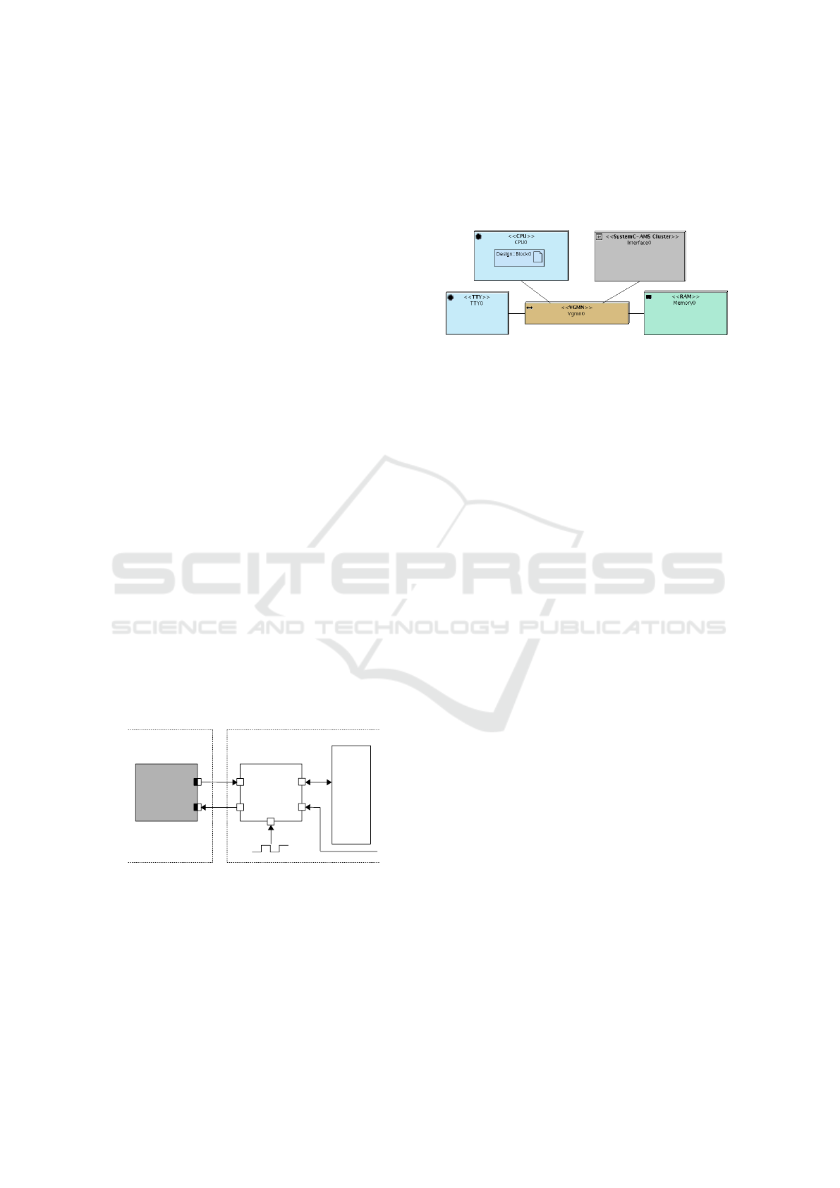
Figure 4 shows a graphical representation of a
TDF cluster, as defined in the SystemC AMS stan-
dard. DE modules are represented as white blocks,
TDF modules as gray blocks, TDF ports as black
squares, converter ports connecting te TDF and the
DE domain as black and white squares, and finally
TDF signals as arrows.
A B Y
R= 1
D= 1
Tm= 6 ms Tm= 4 ms
Tp= 4 ms
R= 3
Tp= 2 ms
D= 0
R= 2
D= 0
Tp= 2 ms
TDF Cluster
Figure 4: TDF Cluster.
TDF modules have the following attributes:
• Module timestep (Tm) denotes the period during
which a module is activated. One module is ac-
tivated only if there are enough samples available
at its input ports.
• Rate (R). A module reads or writes a fixed num-
ber of data samples each time it is activated. This
MODELSWARD 2021 - 9th International Conference on Model-Driven Engineering and Software Development
226
number is annotated to the ports and it is known
as the Port Rate.
• Port timestep (Tp) is the period during which each
port of a module is activated. It also denotes the
time interval between two samples that are being
read or written.
• Delay (D). A delay D can be assigned to a port
to make it store a given number of samples each
time it is activated, and read or write them in the
next activation.
In the example shown in Figure 4, there are TDF ports
between A and B, and B outputs to a converter port.
Port rates, delays and timesteps as well as module
timesteps are given for the TDF modules. TDF clus-
ters thus run continuously according to their schedule,
proposing values on their converter ports to the outer
world (i.e. the interface to/from the digital parts).
4 GENERALIZING
COMMUNICATION BETWEEN
ANALOG AND DIGITAL
DOMAIN
It is obvious that the two models (digital, analog)
described above are difficult to reconcile. Before
this contribution, sending and receiving AMS signals
could not be represented in SysML, thus leading to
manually capture parts of the system. Indeed, analog
and digital domain must be connected with a dedi-
cated hardware unit. Figure 5 ((Cortés Porto et al.,
2019)) shows such a unit, named General Purpose I/O
(GPIO).
GPIO2VCI
p_rdata_ams
p_wdata_ams
TDF_Module
p_clk
p_resetn
p_vci
VCI_Bus
TDF Cluster SoCLib DE
Components
Figure 5: General Purpose I/O unit interfacing between dig-
ital and analog part of the virtual platform.
Definition: A diagram representing analog and dig-
ital hardware (including SW tasks and logical chan-
nels) is called Extended Deployment Diagram (EDD).
Figure 6 shows the EDD of a basic hardware plat-
form featuring an analog circuit (in gray) as well
as digital elements consisting of a processor (CPU),
an interconnection network, a terminal (TTY) and a
memory. The communication links between the hard-
ware components of the digital platform are all based
on the Virtual Component Interconnect standard (VSI
Alliance, 2000).
Figure 6: Extended Deployment Diagram.
To define the communication with analog blocks, we
suggest to use signal sending and receiving in SysML
state machines both for digital or AMS signals. Be-
fore the present contribution, interfacing was relying
on so-called entry code, i.e. handwritten pieces of C
code inserted into the states of the SysML state ma-
chines. In this code, sending and receiving is handled
by read and write primitives from/to GPIOs. Another
limitation was that exchanges were limited to integer
values only, whereas communications between soft-
ware blocks as expressed in SysML can deal with
complex data types.
To address these lacks, we introduce a new rep-
resentation in the SysML block diagram: an interface
that can handle analog signals on one side and transfer
to the digital platform on the other side, and recipro-
cally. To be more precise, TDF signals are sampled,
i.e. they change according to a fixed regular sched-
ule. The digital domain interrogates or updates these
signals, more or less irregularly. This domain thus
acts as a master in system design terminology. Yet,
a problem is to avoid reading or writing obsolete sig-
nals between the digital and the analog domain: those
are signals that are transferred via the GPIO even if
discarded afterwards.
Definition: An AMS Interface is a SysML representa-
tion of all communications on one or several channels
between two functional blocks, one in the analog do-
main and the other one in the digital domain.
Definition: We call a block diagram enhanced with
interfaces an Extended Block Diagram (EBD).
Figure 7 shows an extended block diagram for the
basic system depicted before. This diagram has two
blocks: a software block and an interface block, the
latter being a stereotyped SysML block. On the left
of the Figure, the interface block features four at-
tributes of boolean, integer and floating types. On
the right side, a digital block defines the correspond-
ing attributes. They communicate by a bi-directional
Interfacing Digital and Analog Models for Fast Simulation and Virtual Prototyping
227
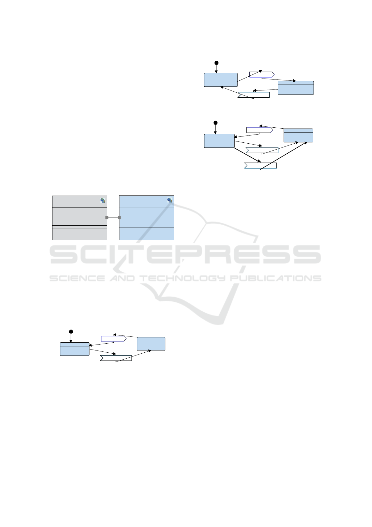
channel which definition is similar to logical channels
between "regular" blocks, except that they represent
a bi-directional communication between analog and
digital domains.
The digital block sends a signal containing two pa-
rameters b and n to the analog interface, which then
receives them and sends an answer, also featuring two
parameters v and d (Figure 8).
Definition: An AMS Interface Channel is a channel
between an interface block and a (regular) SysML
block.
Note that floating point values, necessary to rep-
resent TDF outputs (sampled continuous values), are
allowed in interface channels, but cannot yet be used
in digital blocks. Actually, the use of floats in digi-
tal blocks would require having a model-checker han-
dling float values, which is not currently the case.
block
Block0
- v = 0 : int;
- d : double;
- n : int;
- b : bool;
~ out to_analog(bool b, int n)
~ in from_analog(int v, double d)
amsinterface
Interface0
- d = 0.0 : double;
- v : int;
- b : bool;
- n : int;
~ in from_digital(bool b, int n)
~ out to_digital(int v, double d)
Figure 7: Extended Block Diagram.
Figure 8 shows the state machine representation of
Block0, while Figure 9 shows the behaviour of inter-
face0. The new sending and receiving primitives are
represented in the same style as digital-to-digital op-
erators. However, as certain features are not allowed
in digital-to-digital channels (in particular formal ver-
ification of the digital software part cannot handle
floating point values), we integrated additional checks
into our tool.
WaitForAnalog
SendToAnalog
from_analog(v, d)
to_analog(b, n)
after (1, 1)
after (1, 1)
Figure 8: Minimal analog-digital system: Block.
As explained before, sending and receive actions are
no more captured in the entry code of states, but are
now expressed as operators on transitions between
states. Yet, choices between multiple receptions (as
represented in Figure 3) can now be expressed, lead-
ing to new issues. TDF signals are "sampled" by the
AMS Interface, i.e. their current value at a given time
instant is taken, but they still remain available on the
converter ports during that cycle of the TDF sched-
ule. On the digital side, once a channel has been sent
to_digital(v, d)
from_digital(b, n)
SendToDigital
WaitForDigital
after (1, 1)
after (1, 1)
Figure 9: Minimal analog-digital system: AMS Interface.
WaitForAnalog
SendToAnalog
from_analog(v, d)
to_analog(b, n)
after (1, 1)
after (1, 1)
from_analog2(v, d)
after (1, 1)
Figure 10: Multiple signal reception.
to a channel, its is assumed to be "consumed" one the
sending side. Similarly, once read, an asynchronous
signal is not present anymore in its corresponding
FIFO. In the toy example featured throughout Figures
6 to 12, reception of a signal stemming from the ana-
log domain is always followed by a sending of a sig-
nal to analog, and inversely a sending to the digital
domain is followed by a receiving from that domain.
The state machine of Block0 in Figure 8 shows that
a signal from_analog is first received, then a signal
to_analog is sent.
If we were to replace the state machine of Block0
with the one shown in Figure 10, where a non-
deterministic choice between transitions is made
(reading between two channels), we would have to
discard the one of the two signals which was not read.
Signals from the interface must thus be discarded
in two cases:
• Signals sent from AMS: when the receiving tran-
sition is not taken.
• Signals received by AMS: when the sending tran-
sition is not taken.
AMS Signals sent via an AMS Interface are thus dis-
carded if not received immediately.
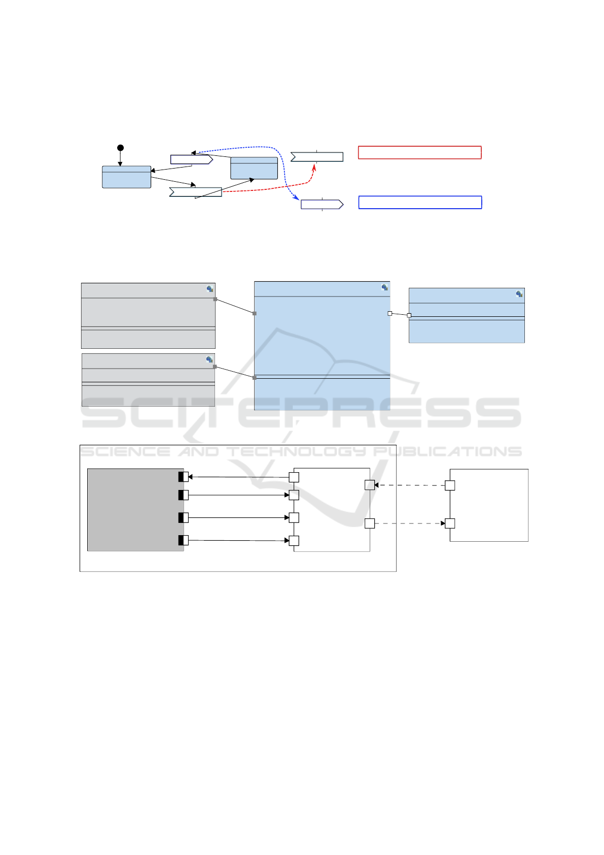
Figure 11 shows how signals can be connected to-
gether, in the same way as for digital signals. In the
given example, the signal to_analog has been con-
nected to the from_digital signal of the interface, the
signal to_digital of the interface still has to be con-
nected to from_analog.
Figure 12 shows on its right the code generated
for the state machine: a POSIX task containing a
switch statement where each state is a case. The
read_gpio2vci and write_gpio2vci primitives pertain-
ing to the sending and receiving of parametrized sig-
nals are shown in the frames, respectively.
MODELSWARD 2021 - 9th International Conference on Model-Driven Engineering and Software Development
228
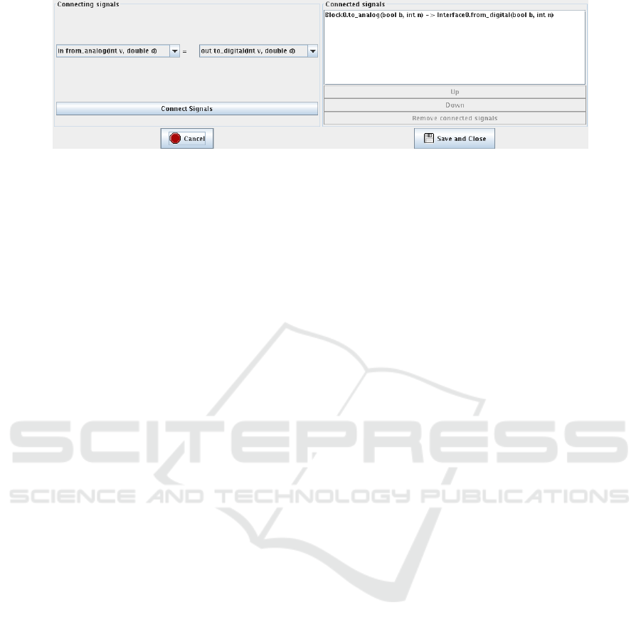
Figure 11: Minimal analog-digital system: connecting signals in the interface.
5 CASE STUDY
In order to illustrate our contribution, in particular its
impact on system models, we consider a simple rover
destined to assist rescuers to find victims buried in
rubble. The rover is equipped with ultrasonic sen-
sors, located in the front, rear, top, and sides. These
sensors allow the rover to detect obstacles to navigate
autonomously (Tanzi et al., 2016). In (Genius et al.,
2019a), a previous model was presented, using entry
code in the state machine diagrams.
The rover adjusts its acquisition behavior based on
the situation. When it detects no obstacles in prox-
imity, the rover decreases its sampling rate, assum-
ing that no obstacles will suddenly appear in its path.
When an obstacle is detected in (very) close prox-
imity, i.e. in its “safety bubble”, the rover adapts
its behavior and increases its acquisition rate. When
the rover has detected obstacles in very close proxim-
ity, exact distances to obstacles become more critical.
A more accurate distance calculations must also take
into account environmental conditions such as tem-
perature and pressure: they can be captured on de-
mand with dedicated sensors.
5.1 Software Model
The model consists of four components: MainCon-
trol, MotorControl and two sensors, a distance sen-
sor and a temperature sensor (Figure 13). The Soft-
ware/Analog Design level representation thus consists
of four SysML blocks. The leftmost blocks, repre-
senting the (new) interfaces to two sensors, are shown
in gray, stereotyped them as interfaces. Note in par-
ticular that three parameters, representing the three ul-
trasonic sensors pointing in different directions, are
contained in the sensorData signal: distance(int dis-
tanceLeft, int distanceFront, intDistanceRight). In the
opposite direction, a signal newRate indicates a mod-
ified sampling rate.
5.2 SystemC AMS Model
Figure 14 shows the SystemC AMS representation
of one of the sensors, the distance sensor, in a dedi-
cated panel which allows a graphical representation of
SystemC AMS modules in the notation of (Accellera
Systems Initiative, 2020) (see Figure 4) integrated
into out tool. The interface appears as DE module
within the cluster. Signal toAMS transmits an eventual
change of the sampling rate, fromAMS the three mea-
sured distances destined to become parameters of the
signal. On the right of the figure, the GPIO2VCI in-
terface is shown. As said above, there can be only one
GPIO2VCI interface for reasons of hardware cost and
simulation time, thus all three parameter values dis-
tanceLeft, distanceRight, distanceFront are contained
in a VCI burst. Whenever an AMS channel read or
write operation is found in the State Machine dia-
gram, a communication with the analog part occurs.
TempData, newRate and control (e.g. switching the
temperature sensor on and off) are signals that are
only read or written depending on the transition taken,
discarded if unused.
We require that all parts of the model are checked
against syntax errors and against semantic aspects de-
scribed in previous section, before any code is gener-
ated. For the analog part itself, this is guaranteed by
the mechanisms described in (Genius et al., 2019b).
6 CONCLUSION
In this paper, we introduce new operators and dia-
grams captured in a SysML way. This eases mod-
eling and understanding of mixed analog/digital sys-
tems. Communications can be expressed in a general
way, abstracting sending of data packets by dealing
with communications by signals containing parame-
ters. From SysML diagrams, the virtual prototype for
co-simulation can be generated in SystemC(-AMS).
Thanks to this new contribution, insertion of hand-
written code for analog/digital communication is no
Interfacing Digital and Analog Models for Fast Simulation and Virtual Prototyping
229
WaitForAnalog
SendToAnalog
from_analog(v, d)
after (1, 1)
to_analog(b, n)
after (1, 1)
while(__currentState != STATE__STOP__STATE) {
switch(__currentState) {
case STATE__START__STATE:
__currentState = STATE__WaitForAnalog;
break;
case STATE__WaitForAnalog:
waitFor((1)*1000000, (1)*1000000);
v = read_gpio2vci_int("Interface0",0);
d = read_gpio2vci_double("Interface0",4);
__returnRequest = executeOneRequest(&__list, &__req0);
clearListOfRequests(&__list);
__currentState = STATE__SendToAnalog;
break;
case STATE__SendToAnalog:
write_gpio2vci_bool(b,"Interface0",0);
write_gpio2vci_int(n,"Interface0",4);
__returnRequest = executeOneRequest(&__list, &__req0);
clearListOfRequests(&__list);
waitFor((1)*1000000, (1)*1000000);
__currentState = STATE__WaitForAnalog;
break;
}
}
to_analog(b, n)
from_analog(v, d)
Figure 12: Block0 with corresponding POSIX code fragment.
block
MainControl
- state = 0 : int;
- sensorOn : bool;
- newRate : int;
- samplingRate = 1 : int;
- rateLow = 10 : int;
- rateMed = 4 : int;
- rateHigh = 1 : int;
- temp : int;
- leftVelocity = 0 : int;
- rightVelocity = 0 : int;
- distanceLeft : int;
- distanceRight : int;
- distanceFront : int;
- speedLow = 2 : int;
- speedNormal = 5 : int;
~ out motorCommand(int leftVelocity, int rightVelocity)
~ out control(bool sensorOn)
~ in tempData(int temp)
~ in sensorData(int distanceLeft, int distanceFront,
int distanceRight)
~ out newRate(int samplingRate)
block
MotorControl
- rightVelocity = 0 : int;
- leftVelocity = 0 : int;
~ in motorCommand(int leftCommand,
int rightCommand)
amsinterface
DistanceSensor
- distanceLeft : int;
- distanceRight : int;
- distancefront : int;
- samplingRate = 10 : int;
- distanceFront : int;
~ out distance(int distanceLeft, int distanceFront,
int distanceRight)
~ in newRate(int samplingRate)
amsinterface
TemperatureSensor
- sensorOn : bool;
- temp : int;
~ in startSensor(bool sensorOn)
~ out temperature(int temp)
Figure 13: Rover system: extended block diagram.
DistanceSensor
Interface
newRate
toAMStoAMS
fromAMSfromAMS
distanceLeftdistanceLeft
distanceFrontdistanceFront
distanceRightdistanceRight
measureDistance
Tm = 10.0 μs
newRate
distanceLeftdistanceLeft
distancefrontdistancefront
distanceRightdistanceRight
GPIO2VCI
toAMStoAMS
fromAMSfromAMS
toAMS
fromAMS
distanceLeft
distanceFront
distanceRight
newRate
Figure 14: Rover system: distance sensor model in the SystemC AMS panel.
longer necessary. Our approach is integrated in a
lightweight, easy-to-use toolkit allowing fast simula-
tion with model animation, formal proof at the push
of a button for the digital part and automated check-
ing of schedulability and causality for the analog part.
The tool is a free software.
The introduction of send-to-analog and receive-
from-analog operators into the state machine dia-
grams opens up interesting questions on the interac-
tion of the semantics of state machine diagrams (dig-
ital) on the one hand and timed data flow (analog) on
the other, which for now is quite restricted; extensions
and their incidence on causality and schedulability on
the analog side will be explored in future work. The
concept is currently being applied to larger case stud-
ies, an automatic braking application, and a portable
echo-stethoscope.
REFERENCES
Accellera Systems Initiative (2020). SystemC AMS exten-
MODELSWARD 2021 - 9th International Conference on Model-Driven Engineering and Software Development
230

sions Users Guide, Version 2.0.
Apvrille, L., de Saqui-Sannes, P., and Vingerhoeds, R.
(2020). An educational case study of using sysml
and ttool for unmanned aerial vehicles design. IEEE
Journal on Miniaturization for Air and Space Systems,
1(2):117–129.
Becoulet, A. (2010). http://www.mutekh.org.
Blondelle, G., Bordeleau, F., and Exertier, D. (2015). Po-
larsys: A new collaborative ecosystem for open source
solutions for systems engineering driven by major in-
dustry players. INSIGHT, 18(2):35–38.
Concepcion, A. I. and Zeigler, B. P. (1988). DEVS for-
malism: A framework for hierarchical model devel-
opment. IEEE Transactions on Software Engineering,
14(2):228–241.
Cortés Porto, R., Daniela Genius, and Ludovic Apvrille
(2019). Modeling and virtual prototyping for embed-
ded systems on mixed-signal multicores. In RAPIDO.
Davare, A., Densmore, D., Meyerowitz, T., Pinto, A.,
Sangiovanni-Vincentelli, A., Yang, G., Zeng, H., and
Zhu, Q. (2007). A next-generation design framework
for platform-based design. In DVCon, volume 152.
Friedenthal, S., Moore, A., and Steiner, R. (2014). A prac-
tical guide to SysML: the systems modeling language.
Morgan Kaufmann.
Fritzson, P. and Engelson, V. (1998). Modelica- a uni-
fied object-oriented language for system modeling and
simulation. In European Conf. on Object-Oriented
Programming, pages 67–90. Springer.
Genius, D., Cortés Porto, R., Apvrille, L., and Pêcheux,
F. (2019a). A tool for high-level modeling of ana-
log/mixed signal embedded systems. In MODEL-
SWARD.
Genius, D., Porto, R. C., Apvrille, L., and Pêcheux, F.
(2019b). A framework for multi-level modeling of
analog/mixed signal embedded systems. In Interna-
tional Conference on Model-Driven Engineering and
Software Development, pages 201–224. Springer.
IEEE (2011). SystemC. IEEE Standard 1666-2011.
Lankhorst, M. et al. (2009). Enterprise architecture at work,
volume 352. Springer.
Lanusse, A., Tanguy, Y., Espinoza, H., Mraidha, C., Gerard,
S., Tessier, P., Schnekenburger, R., Dubois, H., and
Terrier, F. (2009). Papyrus uml: an open source toolset
for mda. In Proc. ECMDA-FA, pages 1–4.
Lee, E. A. (2010). Disciplined heterogeneous model-
ing. In Petriu, D., Rouquette, N., and Haugen, O.,
editors, Proceedings of the ACM/IEEE 13th Inter-
national Conference on Model Driven Engineering,
Languages, and Systems (MODELS), pages 273–287.
LNCS 6395, Springer-Verlag.
Lee, E. A. and Messerschmitt, D. G. (1987). Synchronous
data flow. Proceedings of the IEEE, 75(9):1235–1245.
Li, L. W., Genius, D., and Apvrille, L. (2018). Formal and
virtual multi-level design space exploration. In MOD-
ELSWARD, Springer CCIS, vol 880, pages 47–71.
Ptolemy.org, editor (2014). System Design, Modeling, and
Simulation using Ptolemy II.
Schinz, I., Toben, T., Mrugalla, C., and Westphal, B. (2004).
The rhapsody uml verification environment. In Pro-
ceedings of the Second International Conference on
Software Engineering and Formal Methods, 2004.
SEFM 2004., pages 174–183. IEEE.
Selic, B. and Gérard, S. (2013). Modeling and Analysis
of Real-Time and Embedded Systems with UML and
MARTE: Developing Cyber-Physical Systems. Else-
vier.
Taha, S., Radermacher, A., and Gérard, S. (2010). An
entirely model-based framework for hardware design
and simulation. In DIPES/BICC, volume 329 of IFIP
Advances in Information and Communication Tech-
nology, pages 31–42. Springer.
Tanzi, T., Chandra, M., Isnard, J., Camara, D., Sebastien,
O., and Harivelo, F. (2016). Towards "drone-borne"
disaster management: Future application scenarios.
In ISPRS Annals of Photogrammetry, Remote Sensing
and Spatial Information Sciences, volume III-8, pages
181–189.
Vachoux, A., Grimm, C., and Einwich, K. (2003). Analog
and mixed signal modelling with SystemC-AMS. In
ISCAS (3), pages 914–917. IEEE.
Vidal, J., de Lamotte, F., Gogniat, G., Soulard, P., and
Diguet, J.-P. (2009). A co-design approach for embed-
ded system modeling and code generation with UML
and MARTE. In DATE, pages 226–231. IEEE.
VSI Alliance (2000). Virtual Component Interface Standard
(OCB 2 2.0).
Interfacing Digital and Analog Models for Fast Simulation and Virtual Prototyping
231
