
Transforming Data Flow Diagrams for Privacy Compliance
Hanaa Alshareef
1
, Sandro Stucki
2 a
and Gerardo Schneider
2 b
1
Chalmers University of Technology, Gothenburg, Sweden
2
University of Gothenburg, Gothenburg, Sweden
Keywords:
Privacy by Design, Data Flow Diagrams, GDPR.
Abstract:
Most software design tools, as for instance Data Flow Diagrams (DFDs), are focused on functional aspects
and cannot thus model non-functional aspects like privacy. In this paper, we provide an explicit algorithm
and a proof-of-concept implementation to transform DFDs into so-called Privacy-Aware Data Flow Diagrams
(PA-DFDs). Our tool systematically inserts privacy checks to a DFD, generating a PA-DFD. We apply our
approach to two realistic applications from the construction and online retail sectors.
1 INTRODUCTION
The European General Data Protection Regulation
(GDPR) imposes stringent constraints on how indi-
viduals’ personal data are to be collected and pro-
cessed, stipulating heavy penalties in case of viola-
tions (European Commission, 2016). Complying the
regulation is a hard task and software engineers trying
to meet the required data protection principles often
face a conflict between system and privacy require-
ments (Oetzel and Spiekermann, 2014).
An additional difficulty is that privacy does not
refer to one particular property but rather to a
set of properties, including confidentiality, secrecy,
data minimisation (DM), privacy impact assessment
(PIA), user consent, the right to be forgotten, pur-
pose limitation, etc. So, it does not make sense to talk
about “privacy compliance” but rather to refer to spe-
cific privacy properties. But even when restricted to
a specific privacy property, verifying privacy compli-
ance is in general undecidable (Tsormpatzoudi et al.,
2015; Schneider, 2018).
We therefore advocate the Privacy by Design
(PbD) principle (Cavoukian, 2012), in which any
(computerised) personal data processing environment
should be designed taking privacy into account from
the very beginning of the (software) development pro-
cess It has been argued that PbD is more tractable
than retrofitting legacy software for privacy compli-
ance (see e.g. Danezis et al., 2015).
a
https://orcid.org/0000-0001-5608-8273
b
https://orcid.org/0000-0003-0629-6853
Still, the implementation of privacy principles
such as PbD, PIA or DM requires a lot of work
from software engineers and developers: they con-
sider such principles to be overly complicated and im-
practical, and they lack the necessary knowledge to
implement them (Senarath and Arachchilage, 2018;
Sirur et al., 2018; Freitas and Mira da Silva, 2018).
Hence, despite having been advocated since the mid-
1990s, PbD has gained momentum only in recent
years, mostly due to the GDPR.
An example is the work by Antignac et al. (2016,
2018), who propose an approach to automatically
add privacy checks already at the design level. The
idea is based on model transformations, enhancing
Data Flow Diagrams (DFDs) with checks for specific
privacy concepts, notably concerning retention time
and purpose limitation for each operation on sensitive
(personal) data (storage, forwarding, and processing
of data). The enhanced diagram is called a Privacy-
Aware Data Flow Diagram (or PA-DFD for short). In
that proposal the software engineer designs a DFD,
pushes a button to obtain a PA-DFD, inspects it man-
ually, and then generates a program template from the
PA-DFD that guides the programmer in the concrete
implementation of the privacy checks. Antignac et al.
describe their transformation from DFDs to PA-DFDs
through high-level graphical “rules” but provide nei-
ther a full algorithm nor a reference implementation.
The main purpose of our paper is to provide these
missing pieces.
In summary, we make the following contributions.
1. We give algorithms to check and automatically
transform DFDs into PA-DFDs. We identified
Alshareef, H., Stucki, S. and Schneider, G.
Transforming Data Flow Diagrams for Privacy Compliance.
DOI: 10.5220/0010255002070215
In Proceedings of the 9th International Conference on Model-Driven Engineering and Software Development (MODELSWARD 2021), pages 207-215
ISBN: 978-989-758-487-9
Copyright
c
2021 by SCITEPRESS – Science and Technology Publications, Lda. All rights reserved
207

Customer
Browsing
Amazon
Products
Create
Amazon
Account
Get Customer
Information
Supplier Item
Inventory
Customer Info
Product Info
Product Info
Request
Create Account
Product Info
Request
Figure 1: Example of a DFD: high-level design of part of
the e-store ordering system.
some ambiguities and inaccuracies in the original
description given in the hotspots’ translation by
Antignac et al. (2016, 2018). (Section 3).
2. We provide an open-source Python implementa-
tion of our algorithms,
1
which processes DFD di-
agrams in an XML format compatible with the
popular draw.io platform (Section 3).
3. We evaluate our algorithms on two case studies:
an automated payment system and an online retail
system (Section 4).
2 PRELIMINARIES
We recall here relevant GDPR concepts, the definition
of DFDs, as well as the transformation into PA-DFDs
given by Antignac et al. (2018).
GDPR. The European General Data Protection
Regulation (GDPR) contains 99 articles regulating
personal data processing. The GDPR is organ-
ised around a number of key concepts, most notably
its seven principles of personal data processing, the
rights of data subjects and six lawful grounds for
data processing operations. Relevant to this paper are
the principles of purpose limitation (data may only
be used for purposes to which the data subject con-
sented) and accountability, as well as the right to be
forgotten and the lawful ground of consent. See (Eu-
ropean Commission, 2016) and Hert and Papakon-
stantinou (2016) for more details on the GDPR.
Data Flow Diagrams (DFDs). A data flow dia-
gram (DFD) is a graphical representation of how data
flows among software components. As shown in
Fig. 1, DFDs are composed of activators and flows.
Activators can be external entities (rectangles), pro-
cesses (ellipses) and data stores (double horizontal
lines). Processes may represent detailed low-level
operations or complex high-level functionality that
1
https://github.com/alshareef-hanaa/PA-DFD-Paper
d
d’
External
entity
Process
d
External
entity
d
External
entity
d
Limit
pol
Log
Log
pol
d,pol
d,pol
d
Request
pol
P
External
entity
d
Limit
Request
pol
Log
Log
pol
d,pol
d,pol
d
pol
P
d
Limit Log
Log
d,pol
d’,pol
d’
d’,pol
Process
Request
pol
pol
pol’
P
Reason
P
pol
TransformationsHotspots
Collection
Disclosure
Usage
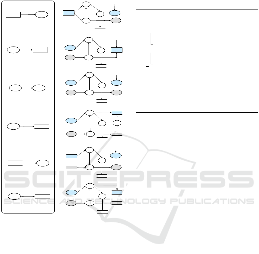
Figure 2: Selection of B-DFD hotspots and corresponding
PA-DFD elements (Antignac et al., 2018).
could be refined into sub-processes (the latter are
drawn as double-lined ellipses). Data flow is repre-
sented by arrows. We chose DFDs since they are a
widely used for modelling digital systems and for se-
curity and privacy analysis (Shostack, 2014; Wuyts
et al., 2014).
Antignac et al. (2016, 2018) extended DFDs with
a data deletion type of flow and a data structure to
specify personal data: (i) the owner of personal data,
(ii) the purpose for which the data can be used con-
sented by the data subject, and (iii) the retention time
for the data. This extension is referred to as Business-
oriented DFD (B-DFD).
Adding Privacy Checks to DFDs. Antignac et al.
(2016, 2018) aimed at (automatically) add privacy
checks to a B-DFD, obtaining a Privacy-Aware Data
Flow Diagram (PA-DFD) which contains relevant
privacy checks for purpose limitation and retention
time, as well as to ensure accountability and policy
management. They defined hotspots in the B-DFD to
perform the transformation compositionally.
The left-hand side of Fig. 2 shows three types
of hotspots, each defined by a pattern of activators
and flows that corresponds to a basic data process-
ing operation, such as “collection”, “disclosure”, etc.
The right-hand side of Fig. 2 shows, for each B-DFD
hotspot, the corresponding PA-DFD containing new
activators and flows for specific privacy mechanisms.
Tables 1 and 2 in Antignac et al. (2018) describes
the privacy properties of interest for each hotspot,
MODELSWARD 2021 - 9th International Conference on Model-Driven Engineering and Software Development
208

pol
Customer
Limit
Request
P
Log
Log
Customer Info
pol
Customer Info,
pol
Customer Info
pol
Customer Info,
pol
Limit
Customer Info,
Request
P
pol
pol
pol
Log
Create Account,
Reason
P
Get Customer
Information
Create
Amazon
Account
Create
Account,
pol
pol
pol’
Log
Create Account
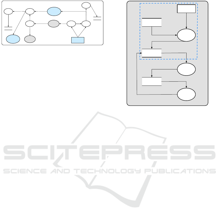
Figure 3: Example of a PA-DFD generated by the old trans-
formation rules
derived from the GDPR. To capture the (new) pri-
vacy checks and to facilitate the transformation, the
set of activator types in PA-DFDs is augmented with
five different “Process” subtypes: “Limit”, “Reason”,
“Request”, “Log” and “Clean”, each corresponding to
a particular privacy enforcement mechanism. “Limit”
inspects whether the purpose of data processing is
compatible with the data subject consent, which de-
mands a policy from the data subject, given by “Re-
quest”. “Log” is used to create log files in a Log data
store. The “Reason” activator is used to get an up-
dated policy corresponding to a newly computed data
value. Finally, “Clean” guarantees that personal data
is eliminated from the data store. See Antignac et al.
(2018) for more details about PA-DFDs.
To illustrate Antignac et al.’s transformation, con-
sider the B-DFD shown in Fig. 1 and (part of) its cor-
responding PA-DFD in Fig. 3. In the figure, “pol”
is a policy related to data “d”. Two rules (collection
and usage) have been applied to a subset of the B-
DFD from Fig. 1 (the part inside the dashed line). The
external entity “Customer” provides “Customer Info”
data and its associated policy “pol”. The data flows to
the “Limit” process which verifies that the data sub-
ject has consented to the use of “Customer Info” for
downstream processing. The consent is specified in
the policy “pol”, received via the “Request” process.
The data value and its policy are logged by the “Log”
process in the “Log” store.
Note that the PA-DFD in Fig. 3 contains a dan-
gling arrow “pol”: this is an unfortunate side-effect
of the way the original transformation rules were for-
mulated (Fig. 2). This and other shortcomings and
inaccuracies are discussed at the end of Section 3.2.
3 FROM B-DFDS TO PA-DFDS
Here we present our algorithms for transforming
B-DFDs to PA-DFDs. The transformation process
consists of two steps: type-inference followed by the
actual transformation. Type-inference ensures that
the input B-DFD is well-formed before it is trans-
Type-inference Transformation
XML/CSV file
B-DFD
XML/CSV file of
well-formed B-DFD
XML/CSV file of
PA-DFD
Customer
Customers
Database
Customer
Info
Create
Account
Create
Account
Login
Get
Customer
info
pol
Customers
Database
Create
Account
Reaso
n
p
Customer
log
Get
Customer
info
LimitREQ
LOG
log
Limit
LOG
REQ
Limit
LOG
Reaso
n
p
REQ
log
Polic
y
Cl
ea
n
pol
pol
PA-DFD
Figure 4: A general architecture of the approach.
formed into a PA-DFD in the second step. Fig. 4
shows the general architecture of our approach.
3.1 Type-inference
The B-DFDs we read from input files are not nec-
essarily well-formed. They may, for example, con-
nect external entities directly, or contain a data dele-
tion flow connecting two process entities rather than
a process and a data store. Such inconsistencies re-
veal errors made by designers. Our tool detects and
reports such issues. For this purpose, we distinguish
between two kinds of B-DFDs: raw B-DFDs corre-
spond to diagrams read from input files and may con-
tain inconsistencies; well-formed B-DFDs are free of
inconsistencies and satisfy all the necessary invariants
required by our transformation algorithm.
We represent both kinds of B-DFDs as attributed
multigraphs with activators as nodes and flows as
edges. Attributes allow us to specify properties of
activators and flows, such as their type or associated
privacy information.
Definition 1. An attributed multigraph G is a tuple
G = (N,F,A,V,s,t,`
N
,`
F
) where N, F, A and V
are sets of nodes, edges, attributes and attribute val-
ues, respectively; s,t : F → N are the source and tar-
get maps; `
N
: N → (A *V) and `
F
: F → (A *V)
are attribute maps that assign values for the different
attributes to nodes and flows, respectively.
Note that the attribute maps are partial, i.e., nodes and
edges may lack values for certain attributes.
Henceforth, we use the letters n, m to denote nodes
and e, f to denote edges. We write e: n m to indi-
cate that e has source s(e) = n and target t(e) = m. We
use “.” to select attributes, writing n.a for `
N
(n)(a)
and f .a for `
F
( f )(a). The set S(G) ⊆ N of source
nodes in G is defined as S(G) = {n | ∃e.s(e) = n};
similarly, T (G) denotes the set of target nodes in G.
A (raw) B-DFD is simply an attributed multigraph
with a fixed choice of attributes A = {type}. The type
attribute describes the type of activators and flows.
Activators can be external entities (ext), processes
Transforming Data Flow Diagrams for Privacy Compliance
209

(proc) and data stores (db); flows are classified as ei-
ther plain data flows (pf ) or data deletions (df ). Fig. 1
shows an example of a B-DFD with five activators (an
external entity, a datastore and three processes) that
are connected by plain flows.
Definition 2. We define the set of data node types
as T
dn
= {ext,proc,db} and the set of raw flow types
as T
rf
= {pf ,df }. A (raw) B-DFD is an attributed
multigraph G with activators as nodes and flows as
edges, and where we fix A and V to be A = {type},
V = T
dn
] T
rf
. In addition, every activator and flow
must have a type, i.e., n.type ∈ T
dn
and f .type ∈ T
rf
must be defined for all n and f .
Since the type attribute plays an important role in all
DFDs, we introduce shorthands for typing activators
and flows. We write n: t to abbreviate n.type = t, and
f : n
t
m to indicate that f : n m and f .type = t.
Well-formed B-DFDs differ from raw B-DFDs
primarily in the choice of flow types. Flows are typed
based on their source and target activators. Only some
combinations of sources, targets and flow types are
valid. They are shown on the left-hand side of Fig. 5.
If a flow does not conform to one of these six cases,
it is ill-typed and will be rejected by our type infer-
ence algorithm. In addition to these flow typing con-
straints, we adopt some common rules from the DFD
literature for well-formed B-DFDs: diagrams may not
contain loops (flows with identical source and tar-
get activators) , activators cannot be isolated (discon-
nected from all other activators), and processes must
have at least one incoming and outgoing flow (see e.g.
Falkenberg et al., 1991; Dennis et al., 2018).
Definition 3. We define the set of data flow types
as T
df
= {in, out,comp,store,read,delete}. A well-
formed B-DFD is an attributed multigraph G, where
A = {type} and V = T
dn
] T
df
. In addition, flows and
activators are subject to the following conditions:
• n.type ∈ T
dn
and f .type ∈ T
df
;
• if f : n
in
m then n: ext and m : proc;
• if f : n
out
m then n: proc and m: ext;
• if f : n
comp
m then n: proc, m: proc and n 6= m;
• if f : n
store
m then n: proc and m: db;
• if f : n
read
m then n: db and m : proc;
• if f : n
delete
m then n: proc and m: db;
• if n : proc then n ∈ S(G) and n ∈ T (G)
• if n : ext or n: db then n ∈ S(G) or n ∈ T (G)
The Type-inference algorithm (Algorithm 1) detects
and reports any ill-formed flows (lines 1–12) and ac-
tivators (lines 13–19). If type inference is successful,
the resulting well-formed B-DFD can safely be trans-
formed into a PA-DFD.
Algorithm 1: Type-inference.
input : A raw B-DFD G
output : A well-formed version of G
1 foreach f : m n ∈ F do
2 if f .type = pf then
3 if m: ext ∧ n : proc then f .type ← in;
4 else if m: proc ∧ n : ext then f .type ← out;
5 else if m: proc ∧ n : proc ∧ m 6= n then
6 f .type ← comp
7 else if m: proc ∧ n : db then f .type ← store;
8 else if m: db ∧ n : proc then f .type ← read;
9 else f is ill-formed;
10 else if f .type = df then
11 if m: proc ∧ n : db then f .type ←delete;
12 else f is ill-formed;
13 foreach n ∈ N do
14 if n : proc ∧ (n /∈ S(G) ∨ n /∈ T (G)) then
15 n is ill-formed
16 else if n : ext ∧ (n /∈ S(G) ∧ n /∈ T (G)) then
17 n is ill-formed
18 else if n : db ∧ (n /∈ S(G) ∧ n /∈ T (G)) then
19 n is ill-formed
3.2 Transformation
Well-formed B-DFDs are guaranteed to be well-
formed, but they do not yet contain any explicit pri-
vacy checks. They are introduced by Algorithm 2,
which transforms each flow in the well-formed B-
DFD into a set of corresponding PA-DFD elements
(see Fig. 5). These PA-DFD elements represent the
functionality for enforcing purpose limitation, reten-
tion time, accountability and policy management.
First we add reason activators for each process in
the well-formed B-DFD. These activators are linked
to each other by a special partner attribute. Each
reason activator is assigned to exactly one process via
this attribute. Likewise, we add a new policy_db ac-
tivator to each data store in the well-formed B-DFD
and link them via their partner attributes. The second
phase of the algorithm transforms each flow based on
its type (i.e., the hotspot that it belongs to). We use
dedicated helper procedures to transform each flow
type (e.g., addInElems, which transforms in flows).
The auxiliary procedures introduce the necessary ac-
tivators and flows for checking and logging each data
flow. The partner attributes of the original flow’s
source and target are used to identify the activators
that supply and transfer the required policy values.
As with B-DFDs, we use attributed graphs to rep-
resent PA-DFDs formally.
Definition 4. Define the set of policy node types as
T
pn
= {limit,request,reason, policy_db} and the set
MODELSWARD 2021 - 9th International Conference on Model-Driven Engineering and Software Development
210
type:in
d
External
Entity
Process
d
External
Entity
Process
Limit
Request
P
Log
pol
pol
d ?
d,pol,v
d,pol,v
Log
pol
Reason
P
type:out
d
Process
External
Entity
External
Entity
d
pol
pol
d ?
d,pol,v
d,pol,v
pol
Limit
Log
Request
P
Reason
P
Log
Process
d,pol,v
d
pol
pol
d ?
d,pol,v
pol
Limit
Log
Request
P
Reason
P
Log
Process Process’
Reason’
P
type:comp
d
Process Process
type:store
d
Data
Process
d,pol,v
Data
d
pol
d ?
d,pol,v
pol
Limit
Log
Request
P
Reason
P
Log
Process
Policy
Clean
P
pol
ref
d,pol,v
type:read
ProcessData
d
d
pol
pol
d ?
d,pol,v
pol
Limit
Log
Request
P
Reason
P
Log
Policy
Data
Process
type:delete
ref
Data
Process
ref
pol
pol
ref ?
ref,pol,v
pol
Limit
Log
Request
P
Reason
P
Log
Policy
DataProcess
ref,pol,v
pol
Figure 5: Well-formed B-DFD and the updated correspond-
ing PA-DFD elements.
of admin node types as T
an
= {log,log_db,clean}.
A PA-DFD is an attributed graph G, where A =
{type,partner} and V = T
dn
] T
pn
] T
an
] T
rf
] N. In
addition, the following must hold:
• n.type ∈ T
dn
] T
pn
] T
an
and f .type ∈ T
rf
;
• if n.partner is defined, then n.partner ∈ N.
In principle, the flows of PA-DFDs ought to be sub-
ject to similar typing conditions as those for well-
formed B-DFDs. Following the principle used for
well-formed B-DFDs, we could type each flow based
on the types of its source and target. For example, the
flows connecting request to limit activators could be
given type reqlim. This would result in eighteen new
flow types. To simplify presentation, we instead use
just two flow types for PA-DFDs as we did for raw
B-DFDs: plain flows (pf ) and deletion flows (df ).
Algorithm 2: Transformation.
input : A well-formed B-DFD G
output : A PA-DFD
1 foreach n ∈ N do
2 if n: proc then
3 add a new node m: reason to G;
4 m.partner ← n; n.partner ← m
5 if n: db then
6 add a new node m: policy_db to G;
7 m.partner ← n; n.partner ← m
8 foreach f ∈ F do
9 if f : in then addInElems (n, f ,G) ;
10 if f : out then addOutElems (n, f ,G) ;
11 if f : comp then addCompElems (n, f ,G) ;
12 if f : store then addStoreElems (n, f ,G) ;
13 if f : read then addReadElems (n, f ,G) ;
14 if f : delete then addDeleteElems (n, f ,G) ;
Comparison of Transformation Rules. The trans-
formation rules presented in Fig. 2 have a few subtle
but important shortcomings that are addressed in our
Transformation algorithm.
First, the rules do not explain how activators with
multiple input and output flows are to be transformed.
Note that all activators on the left of Fig. 2 have at
most one incoming or outgoing flow. It is unclear
which of the new activators and flows shown on the
right should be added only once per rule application,
and which need to be instantiated for every incom-
ing or outgoing flow. We solve this problem by split-
ting the transformation into two distinct steps. In a
first step, we create reason and policy_db nodes as
partners for processes and data stores. In the second
step, each original flow is equipped with the activators
and flows implementing the new privacy checks. This
two-step approach cleanly separates the per-activator
and per-flow aspects of each rule.
Second, the limit and log activators in the orig-
inal rules are set up in a problematic way. Every
limit activator is followed by a log activator that re-
ceives both a policy and a data value. The log acti-
vator logs both values and forwards the data value to
downstream activators. But what if a privacy viola-
tion occurs? The limit activator should inhibit such
violations by blocking unintended flows, passing on
only policy-compliant data values. Hence, policy vi-
olation events never reach the log activator, and are
therefore not logged. This seems highly problematic.
Alternatively limit nodes could pass on all data and
policy values (irrespective of violations), leaving the
log activator to perform the actual filtering. But why
have separate limit and log activators in the first place
then? We resolve this ambiguity by connecting limit
activators directly to the downstream activators and,
Transforming Data Flow Diagrams for Privacy Compliance
211
Get Customer
Information
Create Account ?
Request
P
Log
Log
pol
Create
Amazon
Account
Limit
Create Account
pol
pol
Customer
Limit
Request
P
Log
Log
Customer Info
pol
pol
Customer Info ?
pol
Customer Info,
pol, v
Reason Get
Customer
Information
P
Reason
Create
Amazon
Account
P
Customer Info,
pol, v
Create Account,
pol, v
Create Account,
pol, v
Figure 6: Example of a PA-DFD generated by the updated
rules.
separately, to the log activator. The flow connecting
the limit and log activators carries a special flag v in-
dicating whether a violation took place (see Fig. 5).
Finally, the original “Usage” rule contains a sub-
tle error, which is again related to the way it con-
nects the newly introduced limit and log activators
(see Fig. 2). After the application of this rule, the
process receives a policy value pol in addition to the
data value d it received originally. It passes pol to
the adjacent log activator, presumably without chang-
ing its value, so that any violations related to pol de-
tected by the preceding limit activator can be logged.
But this means that the updated data value d
0
and the
policy value pol are out of sync. Fig. 3 shows an ex-
ample PA-DFD transformed according to the original
rules that clearly illustrates this issue. The “Get Cus-
tomer Information” process receives the “Customer
Info” and the corresponding policy “pol”, then passes
it to the log activator with the processed data “Create
Account”. This means there is a mismatch between
the logged data “Create Account” and the policy value
“pol” which belongs to “Customer Info”. Our algo-
rithm avoids this problem by separating limiting and
logging, which are added on a per-flow basis, from
processing. Fig. 6 shows the PA-DFD produced by
our Transformation algorithm for the same B-DFD.
Now the “Create Account” flow, after having been
transformed according to the comp rule, is protected
by its own limit and log activators, and there are no
longer any dangling flows.
3.3 Our Tool
We have modified the hotspots-based translation
given by Antignac et al. (2016, 2018) in order to
address its ambiguities and inaccuracies. Our tool
for transforming B-DFDs into PA-DFDs implements
algorithms 1 and 2, and uses a third-party applica-
tion for drawing the diagrams. Such drawing soft-
ware should support the drawing of DFDs, be user-
friendly, be easy-to-use, be cross-platform and be
open source. draw.io was the tool of our choice
(draw.io, 2019). As draw.io has no built-in support
Construction
Project
1. Capture
Completed
Tasks via
Smart Sensor
Subcontract
Agreement
Status
Completed
sub-tasks
Scope of Works
Project Status
Information
Project
Database
Real-time Location
Information
2. Auto-
assign Status
Data
BIM
3. Validate
Completed
Works
Tracked Progress
Valid/Invalid
Installation
Figure 7: Part of Automated Payment System DFD.
for B-DFDs, we suggest installing Henriksen’s open
source library (Henriksen, 2018). Since it is easy to
import and export diagrams from/to XML format in
draw.io, our implementation processes B-DFD dia-
grams represented in an XML format and generates
PA-DFD diagrams in the same format. Our tool is
implemented in Python and has been tested on a Mac-
Book Pro.
1
4 CASE STUDIES
To validate our algorithms, we have applied our tool
to models of two realistic applications: an automated
payment system and an online retail system. We il-
lustrate the correctness of our algorithm by running
informal simulations of the two models. Here we fo-
cus on the first case study. The second case study is
described in our tech report (Alshareef et al., 2020).
The DFD for the secure payment system con-
sidered here is due to Chong and Diamantopoulos
(2020); it has been reviewed by domain experts and
models a system for making automatic payments to
subcontractors in a construction project.
We start our evaluation by augmenting the origi-
nal DFD shown in Fig. 7 with static (or design-time)
policy information. Table 1 shows an extract: each
flow is assigned a unique identifier (F_id), its Label
(from the DFD), a Purpose (to check against the data
subject consent), a PD flag indicating if the data is
personal, and a Data_type (e.g., “image” or “email”).
Next, we transform the B-DFD thus obtained into
a PA-DFD, parts of which are shown in Fig. 8.
MODELSWARD 2021 - 9th International Conference on Model-Driven Engineering and Software Development
212
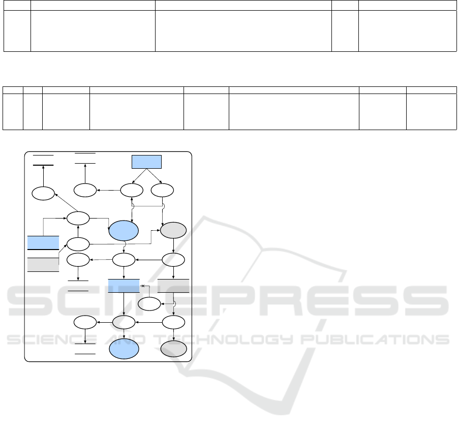
Table 1: Design Time Information for B-DFD Automated Payment System.
F_id Label Purpose PD Data_type
f
1
Completed sub-tasks Capturing completed sub-tasks True video, images and string
f
2
Scope of Works Knowing subcontractors contractual duties True string
f
3
Real-time Location Information Project monitoring True video, images and string
f
4
Status Sending up to date project information to IBM True video, images and string
Table 2: Run-time Information for B-DFD/PA-DFD Automated Payment System.
D_id F_id Dsub Pol/Consent Expiry Content Fwd. in B-DFD Fwd. in PA-DFD
d
1
f
1
SubcontractorX Capturing completed sub-tasks end of 2020 "streaming videos" and "image_1.jpg" Yes Yes
d
2
f
2
SubcontractorX Identifying assigned tasks end of contract "facade panel installation" Yes Yes
d
3
f
3
SubcontractorX Recording the work status end of contract "streaming videos" and "image_2.jpg" Yes Yes
d
4
f
4
ProjectX Assigning project info to BIM end of 2021 "Project info:name, desc, status, subcontract,etc" Yes Yes
d
5
f
1
SubcontractorY Taking pictures for advertisements end of 2020 "streaming videos" and "image_3.jpg" Yes No
Construction
Project
1. Capture
Completed
Tasks via
Smart Sensor
Subcontract
Agreement
Completed
sub-tasks
Real-time
Location Info ?
Pol,v
Clean1
P
Log
Limit1
Request1
P
Pol
Pol
Reason p
Capture
Completed
Tasks …
Log1
Completed
sub-
tasks,Pol,v
Completed
sub-
tasks,Pol,v
Completed
sub-tasks
Pol
Policy
Limit2
Request2
P
Scope of
Works
Pol
Pol
Pol
Scope of
Works ?
Log2
Log
Scope of Works,
pol, v
Scope of
Works, pol,
v
Project
DataBase
Policy
Limit3
Request3
P
Pol
Log3
Log
Pol
Pol
Pol
ref
Real-time
Location Info,
Real-time
Location
Info, Pol,v
Real-time
Location Info
2. Auto-
assign Status
Data
Reason p
Auto-
assign
Status Data
Pol
Limit4
Request4
P
Pol
Status
Pol
Status ?
Log4
Log
Status,
Pol,v
Status,
Pol,v
Figure 8: Part of Automated Payment System PA-DFD.
Finally, we perform an informal simulation of the
payment system, illustrating that the PA-DFD gener-
ated by our proof-of-concept tool enforces the desired
GDPR properties (purpose limitation and account-
ability). To run the informal simulation, we assume a
set of dynamic information provided by users during
runtime. An excerpt is shown in Table 2. Each row
consists of a unique data identifier (D_id) with five
attributes: F_id identifies the flow carrying the data;
DSub the data subject; Pol/Consent the consented pur-
poses; Expiry the expiration time; Content the ac-
tual data. The last two columns of Table 2 indicate
whether the given data values are forwarded to down-
stream activators in the B-DFD and PA-DFD, respec-
tively, during the simulation. They show that the PA-
DFD prevents some data from being processed, while
the B-DFD processes all data regardless of the data
subject’s consent since there are no privacy checks.
Consider, for example, the “Completed sub-tasks”
flow between “Construction Project” and Process 1
in the original DFD. This flow carries sensitive infor-
mation collected by the smart sensor, which needs to
be checked and limited according to the subcontrac-
tor’s privacy policy (following the principle of pur-
pose limitation). This is achieved via corresponding
limit and request activators in the PA-DFD. To illus-
trate this, we consider two scenarios, represented by
the data values d
1
and d
5
in the first and last rows
of Table 2. In Scenario 1, the data subject “Subcon-
tractorX” permitted the smart sensor to collect infor-
mation until the end of 2020. Hence, the informa-
tion d
1
is forwarded from the limit node to Process 1
and logged (according to the accountability principle)
in the log store along with its policy and a flag indi-
cating that no violation occurred. In Scenario 2, the
limit node prevents the data value d
5
from being for-
warded to Process 1 since the intended purpose of the
flow (“Capturing completed sub-tasks”) is not com-
patible with the purpose (“Taking pictures for adver-
tisements”) to which the data subject (“Subcontrac-
torY”) consented. Furthermore, this event is logged
in the log store and identified as a privacy violation.
Contrast the above scenarios with the original
DFD in which the subcontractors’ data is uncondi-
tionally forwarded to processes and stored without
regard for any GDPR principle; the data can be col-
lected and used without limitation, for any purpose.
5 RELATED WORK
Basin et al. (2018) have recently proposed a method-
ology to audit GDPR compliance by using business
process models. They identify “purpose” with “pro-
cess” and show how to automatically generate pri-
vacy policies and detect violations of data minimisa-
tion at the modelling level. They highlight the dif-
ficulty of representing purpose at the programming
language level, and provides convincing arguments on
why GDPR compliance cannot be entirely automated.
Transforming Data Flow Diagrams for Privacy Compliance
213

Schaefer et al. (2018) present a definition of rules
for achieving Confidentiality-by-Construction, where
functional specifications are replaced by confidential-
ity specifications listing which variables contain se-
crets. Though the approach seems interesting, it has
(to the best of our knowledge) not been implemented.
Tuma et al. (2019) analyse information flow poli-
cies at the modelling level. They focus on data confi-
dentiality and integrity, and introduce a graphical no-
tation based on DFDs to algorithmically detect design
flaws “in the form of violations of the intended secu-
rity properties”. They provide an Eclipse-based im-
plementation. Their approach is also based on DFDs
but has different objectives: while we focus on the
implementation of model transformation for specific
privacy checks, Tuma et al. focus on the detection of
design flaws associated with security properties.
Our paper distinguishes itself in that none of the
above has taken the approach to automatically add
privacy checks to design models.
6 CONCLUSIONS
We have provided algorithms to automatically trans-
late DFD models into privacy-aware DFDs (PA-
DFDs) as well as a proof-of-concept implementation
integrated into a graphical tool for drawing DFDs.
Obtaining the algorithms (from the existing concep-
tual transformation) was not easy as some aspects
of the transformation were subtle and ambiguous not
allowing for a direct implementation. We have ad-
dressed these conceptual flaws and evaluated them
through two case studies: an automated payment sys-
tem and an online retail system.
One limitation of our approach is that the dia-
grams resulting form our transformation can be large,
making it difficult to visualise them. That said, the
intended use of this tool is as an intermediate step
in the design and development process, so the soft-
ware architect can still be able to inspect (and mod-
ify) only small and relevant subsets of the PA-DFD.
Our next step is to implement an algorithm to auto-
matically synthesise a template from the PA-DFD in
Java or Python. We will provide the programmer with
predefined libraries to be used as building blocks for
implementing such privacy checks.
REFERENCES
Alshareef, H., Stucki, S., and Schneider, G. (2020). Trans-
forming data flow diagrams for privacy compliance
(long version). CoRR, abs/2011.12028.
Antignac, T., Scandariato, R., and Schneider, G. (2016). A
privacy-aware conceptual model for handling personal
data. In ISoLA’16, pages 942–957.
Antignac, T., Scandariato, R., and Schneider, G. (2018).
Privacy compliance via model transformations. In
IWPE’18, pages 120–126. IEEE.
Basin, D., Debois, S., and Hildebrandt, T. (2018). On pur-
pose and by necessity: compliance under the GDPR.
In FC’18, pages 20–37. Springer.
Cavoukian, A. (2012). Privacy by design: origins, mean-
ing, and prospects for assuring privacy and trust in the
information era. In Privacy Protection Measures and
Tech. in Business Org., pages 170–208. IGI Global.
Chong, H.-Y. and Diamantopoulos, A. (2020). Integrat-
ing advanced technologies to uphold security of pay-
ment: Data flow diagram. Automation in Construc-
tion, 114:103–158.
Danezis, G., Domingo-Ferrer, J., Hansen, M., Hoepman,
J.-H., Le Métayer, D., Tirtea, R., and Schiffner, S.
(2015). Privacy and data protection by design. ENISA
Report.
Dennis, A., Wixom, B. H., and Roth, R. M. (2018). Systems
analysis and design. John wiley & sons.
draw.io (2019). draw.io. https://www.draw.io/.
European Commission (2016). General data protection
regulation (GDPR). Regulation 2016/679, European
Commission.
Falkenberg, E., Pols, R. V. D., and Weide, T. V. D. (1991).
Understanding process structure diagrams. Informa-
tion Systems, 16(4):417 – 428.
Freitas, M. and Mira da Silva, M. (2018). GDPR compli-
ance in SMEs: There is much to be done. J. Inform.
Systems Eng., 3(4):30.
Henriksen, M. (2018). Draw.io libraries for threat mod-
eling diagrams. https://github.com/michenriksen/
drawio-threatmodeling.
Hert, P. D. and Papakonstantinou, V. (2016). The new gen-
eral data protection regulation: Still a sound system
for the protection of individuals? Computer Law &
Security Review, 32(2):179–194.
Oetzel, M. C. and Spiekermann, S. (2014). A systematic
methodology for privacy impact assessments: a de-
sign science approach. European Journal of Informa-
tion Systems, 23(2):126–150.
Schaefer, I., Runge, T., Knüppel, A., Cleophas, L., Kourie,
D., and Watson, B. W. (2018). Towards con-
fidentiality-by-construction. In ISoLA’18. Springer.
Schneider, G. (2018). Is privacy by construction possible?
In ISoLA’18, pages 471–485. Springer.
Senarath, A. and Arachchilage, N. A. (2018). Why devel-
opers cannot embed privacy into software systems? an
empirical investigation. In EASE’18, pages 211–216.
Shostack, A. (2014). Threat modeling: Designing for secu-
rity. John Wiley & Sons.
Sirur, S., Nurse, J. R., and Webb, H. (2018). Are we there
yet? Understanding the challenges faced in complying
with the general data protection regulation (GDPR). In
MPS’18, pages 88–95. ACM.
Tsormpatzoudi, P., Berendt, B., and Coudert, F. (2015). Pri-
vacy by design: From research and policy to prac-
MODELSWARD 2021 - 9th International Conference on Model-Driven Engineering and Software Development
214

tice - the challenge of multi-disciplinarity. In APF’15,
pages 199–212. Springer.
Tuma, K., Scandariato, R., and Balliu, M. (2019). Flaws
in flows: Unveiling design flaws via information flow
analysis. In ICSA’19, pages 191–200. IEEE.
Wuyts, K., Scandariato, R., and Joosen, W. (2014). Empir-
ical evaluation of a privacy-focused threat modeling
methodology. J. of Syst. and Soft., 96:122–138.
Transforming Data Flow Diagrams for Privacy Compliance
215
