
Mesh Animation Compression using Skinning and Multi-chart
Displacement Texture
Andrej F
´
usek
1 a
, Adam Rie
ˇ
cick
´
y
2,3 b
, Martin Stuchl
´
ık
3 c
and Martin Madaras
1,2,3 d
1
Faculty of Informatics and Information Technologies, Slovak University of Technology in Bratislava, Slovakia
2
Faculty of Mathematics, Physics and Informatics, Comenius University in Bratislava, Slovakia
3
Skeletex Research, Slovakia
Keywords:
Computers and Graphics, Animation, Compression, Skeleton.
Abstract:
Realistic animations of 3D models are currently very complex, and to stream them over a network in real-time,
it is necessary to use compression. Currently, many different methods can be used. Some of them use skeleton
transformation as an approximation of the animation, others use remeshing for decreasing mesh complexity. In
this paper, a novel method of 3D animation compression is presented. It is based on reconstructing a 3D mesh
from a 2D displacement texture and subsequent skeletal skinning enhanced by a surface tuning. The tuning
is performed by displacing the skinned vertices according to high-frequency details encoded in a Differential
Texture since the output of the skinning is just an approximation of the original animation. Skinning weights
are encoded in another new texture type - Skinning Map. In each frame of the streaming animation, just a new
skeleton pose and the Differential Texture are needed to be sent. The proposed method has a high compression
ratio for various animations because the pose is a small data structure and the Differential Texture contains just
high-frequency details and on top of that, it can be compressed as video. Furthermore, differences between
original and reconstructed animation are minimal, as evidenced by visual and numerical comparisons.
1 INTRODUCTION
Skeletal animation of 3D models is commonly used
in many animated movies or games. However, to
contain more details in the animation, the skeleton is
not sufficient. The other extreme, a mesh animation,
defines the position of each vertex of the model for
each animation frame. This way, high-quality anima-
tions can be achieved. However, the amount of data
is very large, so actually, it is a problem to stream
it in real-time (e.g. in an online game). There are
some compression methods that address these prob-
lems and they are analyzed in this paper. Two main
approaches
1
are suitable for the animation compres-
sion: remeshing and skinning.
The first approach converts a mesh from each an-
imation frame into a format that is either better for
compression or just contains fewer vertices. The
a
https://orcid.org/0000-0002-2685-8692
b
https://orcid.org/0000-0002-1546-0048
c
https://orcid.org/0000-0001-8556-8364
d
https://orcid.org/0000-0003-3917-4510
1
Also PCA-based methods can be used, but they are not
listed because of their poor properties (Brice
˜
no et al., 2003).
second one uses skinning as an approximation of
the complicated animation and some algorithms ex-
tend this method by corrections to this approximation.
There are also methods that are a combination of these
two, and they use a texture for defining the mesh it-
self. However, the mesh surface is stretched to the
whole texture, and therefore it is not optimal.
We propose a novel method of mesh animation
compression, based on a combination of state-of-the-
art methods for representing the mesh by texture and
for skinning. In general, skinning produces just an
approximation of the input mesh animation. There-
fore, high-frequency details, that cannot be contained
in skeletal animation, are stored in a Differential Tex-
ture. All the textures are generated using a parame-
terization with near-optimal stretch and consequently,
the reconstruction quality is high. Due to skinning,
the Differential Texture contains just high-frequency
details, so the compression ratio achieves also high
values. Further, the proposed method offers an option
to set the level of detail so that the user can choose a
trade-off between the quality and compression ratio.
Properties of our proposed method are evaluated on
several mesh animations and with different levels of
Fúsek, A., Rie
ˇ
cický, A., Stuchlík, M. and Madaras, M.
Mesh Animation Compression using Skinning and Multi-chart Displacement Texture.
DOI: 10.5220/0010244302010208
In Proceedings of the 16th International Joint Conference on Computer Vision, Imaging and Computer Graphics Theory and Applications (VISIGRAPP 2021) - Volume 1: GRAPP, pages
201-208
ISBN: 978-989-758-488-6
Copyright
c
2021 by SCITEPRESS – Science and Technology Publications, Lda. All rights reserved
201

detail.
The high compression ratio makes this method
suitable for streaming high-detail animations for var-
ious VR applications, games, or other entertainment.
For example, human animation, along with facial an-
imations (like mouth or wrinkles movement) can be
effectively compressed by our method.
2 RELATED WORK
There are already several different approaches to
mesh animation compression. However, for better
understanding them and also our method, we firstly
analyze two problems related to the mesh animation,
static mesh representation, and skeletal animation.
2.1 Static Mesh Representation
Each frame of the mesh animation is basically a static
mesh which usually consists of triangles and it repre-
sents the surface of some 3D object. The triangle is
defined by three indices to a vertex list. However, the
meshes are mostly irregular and the representation is
relatively difficult to compress efficiently.
Since the mesh defines just the 2D surface of the
3D model, it is possible to represent the mesh by a 2D
image which could be compressed by some classic
techniques, e.g. wavelet compression. This idea was
first presented by Gu et al. (Gu et al., 2002). In such a
representation, some parameterization of the surface
needs to be defined and its quality can be measured
as L
2
stretch, defined by Sander et al. (Sander et al.,
2001). This value also predicts the quality of a mesh
reconstructed from the image (Sander et al., 2002),
since the conversion causes remeshing and subse-
quently a lossy compression of the original model.
For optimizing the parameterization, there are
many stretch-minimization methods. They can be
divided into two groups, based on the boundary of
the 2D domain. From commonly used methods,
Yoshizawa et al. (Yoshizawa et al., 2004) fix the
boundary to a convex shape (circle or square) and
methods by Smith and Schaefer (Smith and Schaefer,
2015) and Rabinovich et al. (Rabinovich et al., 2017)
let the boundary free during the minimization.
Bijectivity is also an important property of the pa-
rameterization, because if it is not bijective, some sur-
face details, like corners or other extremes, cannot be
preserved. Fortunately, there are some parameteriza-
tion methods that guarantee bijectivity. The first of
them was presented by Tutte (Tutte, 1960) where the
bijective parameterization of any topological disk can
be obtained by solving a linear system.
Currently, many parameterization methods can be
used to represent the mesh by a texture. For ex-
ample, Tarini et al. (Tarini et al., 2004) designed a
PolyCube-Maps, where the mesh was simplified to
a set of aligned cubes and a vertex of the mesh was
mapped to a point on the surface of the nearest cube,
similarly to classic cube-map. Usai et al. (Usai et al.,
2015) designed a method which divides the mesh sur-
face according to a curve-skeleton and maps segments
created this way onto rectangles which were placed
into the final texture.
Geometry Images (GIM) (Gu et al., 2002) cuts the
model surface to reach a topological disk with low-
est possible stretch. The surface is then mapped onto
a square texture according to Floater (Floater et al.,
1997). Thus obtained parameterization is bijective,
however, has a high L
2
stretch value, which is sub-
sequently minimized using the method of Yoshizawa
et al. (Yoshizawa et al., 2004). As the last step, the
colors of the texture pixels are set according to the
mapped 3D position (red = X, green = Y, blue = Z). In
reconstruction, each 2 by 2 quad of neighboring pixels
form two triangles and therefore, full texture forms a
mesh which is similar to the original one. Since the
full surface of the arbitrary model is mapped onto the
single square, low stretch values cannot be achieved
and so the reconstruction quality of more complex
models is poor.
Multi-Chart Geometry Images (MCGIM) (Sander
et al., 2003) is also based on the idea of represent-
ing the whole mesh by a single image, however, un-
like GIM, this method divides the surface into several
segments, called also charts. L
2
stretch of each chart
parameterization is then minimized, leaving bound-
aries of the charts free during the optimization. This
way, values of L
2
stretch are near ideal and therefore,
the reconstruction quality is also higher. All parame-
terized charts are placed onto a single rectangular tex-
ture and their rasterized boundaries are overwritten to
guarantee a watertight mesh after the reconstruction.
As a final step, mesh optimization is performed in or-
der to achieve even higher quality, especially in areas
with sharp features of the represented model.
2.2 Skeletal Skinning
Most common animations express the movement of a
human or some animal. This kind of animation can
be approximated by a skeleton transformation. The
skeleton itself defines a topology of the model, it con-
sists of bones connected in a hierarchy, and by rota-
tion (and translation) of them, a simple animation can
be achieved (Jacobson and Sorkine, 2011).
Skinning of the mesh is a process, where the mesh
GRAPP 2021 - 16th International Conference on Computer Graphics Theory and Applications
202

is deformed according to the skeleton pose. Each
vertex of the mesh has defined weights which de-
scribe how much each bone influences that vertex
and the bones themselves have defined transforma-
tion matrices computed from the rotations and trans-
lations (Lander, 1998).
The simplest skinning method, called Linear
Blend Skinning (LBS) (Lander, 1998) uses the weight
to linearly interpolate between vertex position trans-
formed by each bone independently. This approach
results in smooth deformation of the mesh, but also
significant artifacts, like volume collapse near skele-
ton joints, if extreme rotation (near 180 degrees twist)
is performed. This method is very simple, but the
animation in these extreme cases looks very unnatu-
ral. Fortunately, several improvements to this method
were designed later.
First automatic method (without need to manu-
ally change the skeleton), Spherical Blend Skinning
(SBS) (Kavan and
ˇ
Z
´
ara, 2005), interpolates quater-
nions instead of the transformation matrices. This ap-
proach prevents the collapse of volume and requires
just a few more operations in rendering than LBS.
There are many newer methods, e.g. Skinning
with Dual Quaternions (Kavan et al., 2007), but we
would like to pay special attention to the state-of-the-
art method (Le and Hodgins, 2016), called Real-time
Skeletal Skinning with Optimized Centers of Rotation
(ORCS). The basic idea of this method is to rotate
vertices around optimized centers, not just joints of
the skeleton as in other skinning methods. The cen-
ters are pre-computed in an initialization step, as av-
erage positions of vertices with similar weights, and
the real-time algorithm is similar to SBS. The output
of this method looks more realistic and preserves the
same volume near joints during the whole animation,
even at extreme rotations.
2.3 Current Methods of Mesh
Animation Compression
Currently, there are many different approaches to an-
imation compression. The first group of algorithms is
based on Principal component analysis (PCA), for ex-
ample, a method by Sattler et al. (Sattler et al., 2005)
or Lee et al. (Lee et al., 2007). These methods are
based on the fact that in all common mesh animations,
many vertices are moved very similarly between the
frames and therefore use PCA for extracting the main
components of this information.
Geometry Videos (Brice
˜
no et al., 2003) converts
a mesh from each frame of the animation to a 2D
image using the GIM method and encodes result-
ing images as MPEG video. Multi-chart Geome-
try Video (Mamou et al., 2006) is very similar, but
uses MCGIM instead of GIM. These methods pro-
duce representations with higher quality than PCA-
based methods.
Although none of these methods takes the advan-
tage that most mesh animations can be approximated
by skeleton transformation, there are several different
methods based on that idea. In Skinning Mesh Ani-
mations (SMA) (James and Twigg, 2005), the mesh
animation is automatically converted into a skeleton-
based animation, and differences from the original
one are encoded using a method similar to Eigen-
Skin (Kry et al., 2002). However, compression is not
a primary goal of this method so it does not support
mesh simplification (level of detail).
There is also Skeletex representation (Madaras
et al., 2018) where the mesh is represented by a skele-
ton and several vector-displacement textures, one for
each bone of the skeleton. It could be used for ani-
mation compression as well, but the resulting anima-
tion does not guarantee C
1
continuity (there are visi-
ble edges in segment boundaries).
The method by Feng et al. (Feng et al., 2010) uses
an approach similar to GIM to represent the rest-pose
mesh and the animation is performed by skinning of
the reconstructed mesh. Skinning weights and bone
indices are encoded with the same parameterization
as vertex positions.
2.4 Quality Metrics
To decide whether some compression method is
good or not, existing evaluation metrics will be used
to evaluate the animation reconstructed from com-
pressed representation.
If reconstructed mesh in each frame has the same
connectivity as the original one, a metric defined by
Karni and Gotsman (Karni and Gotsman, 2004) could
be used. It considers also how much the vertices move
on average during the whole animation.
However, many methods convert the original
mesh from the animation to a representation with dif-
ferent connectivity. Therefore, a metric that is able
to compare two surfaces has to be used. Most com-
mon is Hausdorff distance which measures the dis-
tance from each vertex of the first mesh to the near-
est point on the second mesh surface (Rockafellar and
Wets, 2009). One can compute a mean or max value
of these measured distances (Cignoni et al., 1998).
Payan et al. (Payan et al., 2008) compute the average
of the max Hausdorff distances for the entire anima-
tion to measure the distortion of the reconstruction.
Mesh Animation Compression using Skinning and Multi-chart Displacement Texture
203
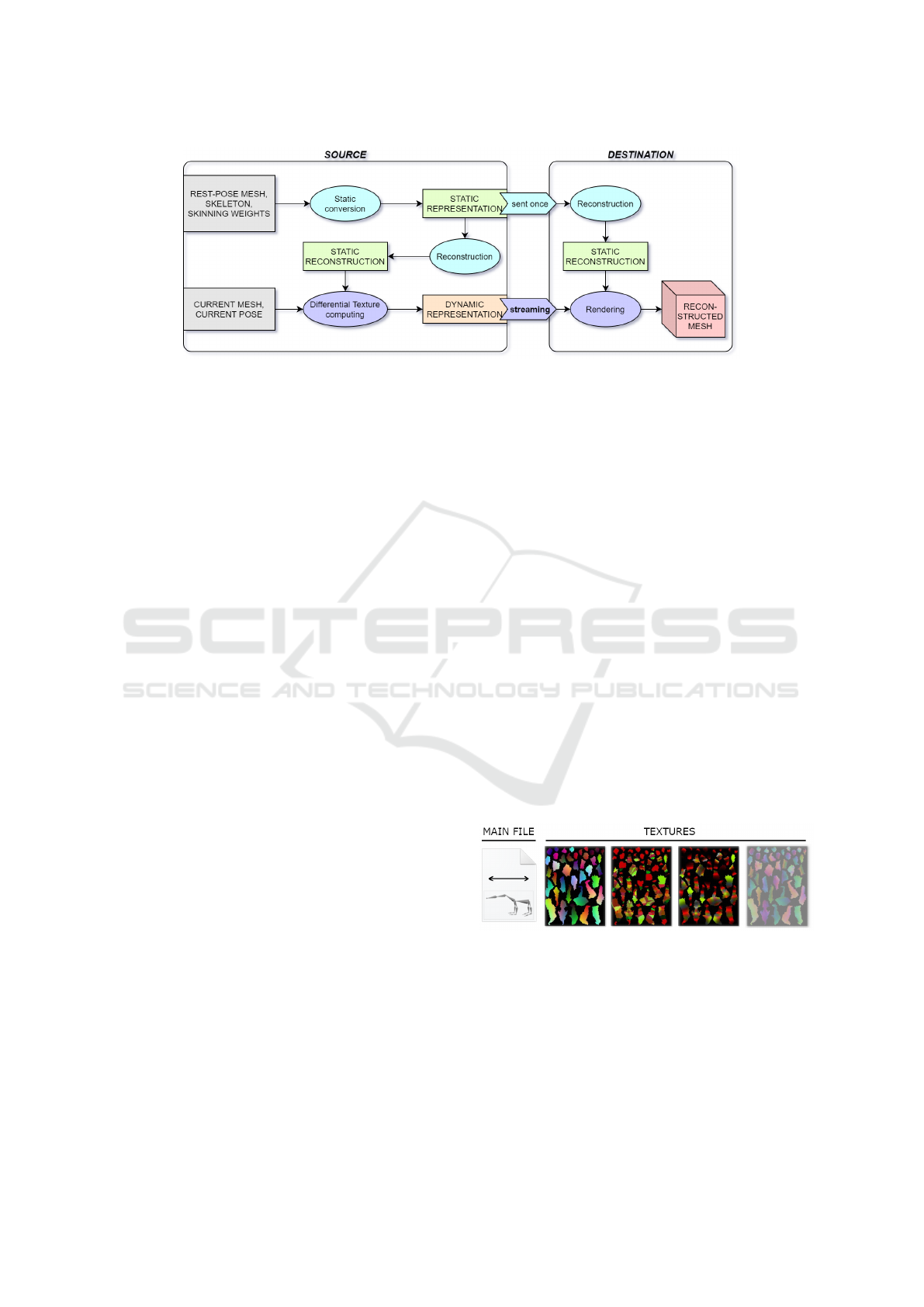
Figure 1: Overview diagram of our method for animation compression and reconstruction.
3 ANIMATION
REPRESENTATION
The basic idea of our proposed compression method
is to represent a static 3D model in a rest pose and its
movement separately. To enable real-time streaming
of highly detailed animation, the movement definition
is designed to be as small as possible.
Our designed method of animation compression
itself is based on skeletal skinning of mesh recon-
structed from MCGIM and subsequently applying
corrections from a texture stream. Therefore, the
static model must contain also skinning weights and
the skeleton, and the movement consists of skeleton
poses and textures with the corrections. All proper-
ties of vertices (positions, skinning weights, normals,
corrections, etc.) are encoded in 2D textures with
the same parameterization. An overview diagram ex-
pressing the whole method and inside processes is in
Figure 1.
3.1 Conversion
Within a conversion of input mesh animation, there
are two processes: an initial conversion of the static
3D model in a rest pose and a real-time conversion of
the animation frames.
3.1.1 Static Model Conversion
The input of the initial conversion is an arbitrary mesh
in a rest pose along with its skeleton and skinning
weights. These structures could be generated using an
existing method for conversion the mesh animation to
a skeletal one (James and Twigg, 2005). The output
is a representation of the static model which consists
of one main file that contains model dimensions, po-
sition, skeleton, and several textures. These files need
to be sent just once, at the start of the streaming pro-
cess. An example of them can be seen in Figure 2.
The main part of this conversion is to generate
the geometry image and it is inspired mostly by the
MCGIM method by Sander et al. (Sander et al., 2003).
Firstly, the surface of the input mesh is segmented
and each segment is parameterized using the bijec-
tive stretch minimizing method by Smith and Schae-
fer (Smith and Schaefer, 2015). This way, a set of 2D
charts with near-ideal stretch is created. The follow-
ing steps are placing them onto a single rectangular
image, sampling of the image, and zippering in order
to guarantee a water-tight mesh after reconstruction.
In addition to the image, we preserve also a pa-
rameterization as the output of the MCGIM creation,
because it is necessary for exporting also all other im-
ages. To enable skeletal skinning of a mesh recon-
structed from the MCGIM, we design two new texture
types. Index Skinning Map (ISM) encodes the indices
of bones and Weight Skinning Map (WSM) encodes
amounts of bone influences.
Figure 2: Example files of the static model representation
(bear model). From left: the main file, MCGIM, ISM,
WSM and optional normal map.
Since each vertex of the input mesh has a skinning
weights, exporting them to the skinning maps are rel-
atively simple. In most cases, the vertex has a limited
number of influencing bones to 4, but because of the
parameterization, some output texture pixels can be
related to more bones. However, the amount of in-
fluence by the fifth and next bones is practically very
GRAPP 2021 - 16th International Conference on Computer Graphics Theory and Applications
204

small and can be neglected. A similar approach was
used in the method by Feng et al. (Feng et al., 2010).
The bone indices are encoded during exporting
ISM by simple bit-wise operations - since four bone
indices need to be encoded in three channels (red,
green, blue). For WSM export, the weights encoding
are based on the fact that a sum of all weights for each
vertex is equal to 1.0. Therefore, one of the weights,
the highest one, is not encoded. Other weights (3 or
less) are written directly to color channels of corre-
sponding pixels. They are sorted in descending order
and to improve the precision of the quantization, each
weight is multiplied by its order in the original weight
list.
3.1.2 Real-time Conversion
During the processing of each frame in real-time
streaming of animation, an input is a new mesh with
the same connectivity as the rest-pose mesh and new
pose of the skeleton that could be obtained using a
method for extraction pose from current frame (James
and Twigg, 2005).
To generate a texture used to correct errors from
skinning approximation, the skinning of the recon-
structed mesh is performed and thus deformed mesh
is compared with the new input mesh. Differences
between these two surfaces are computed for each re-
constructed vertex using the nearest point on the sur-
face of the original mesh and they are just exported
to a new Differential Texture (DT) using the parame-
terization computed in the initial conversion. For ac-
celeration of this process, just a small triangles subset
of the original mesh is considered while finding the
nearest point.
Therefore, just the new pose and this texture need
to be sent in streaming. In addition, classic video en-
coders can be used to compress the texture stream,
since it forms a 2D video during the animation. For
example, MPEG compression was used in this paper.
3.2 Reconstruction
Reconstruction of the animation can be divided
into an initial and a real-time algorithm as well.
Within initialization, the rest-pose mesh is recon-
structed from the MCGIM just like in the original
method (Sander et al., 2003) and both skinning maps
are decoded by simple applying inverse operations to
the encoding.
Since the ORCS method by Le and Hodgins (Le
and Hodgins, 2016) is used to skin the reconstructed
mesh, the centers of rotation must be computed in
the initialization step as well. This computation is
performed according to the procedure in the origi-
nal method, but the center positions are stored in a
texture, similar to the way how vertex positions are
stored in the MCGIM. The output of the initial recon-
struction is used in a shader for a real-time rendering
of the animation.
For the reconstruction of one animation frame
in real-time, transformation matrices for ORCS are
computed from the skeleton and its new pose. The
rest-pose mesh is skinned as in ORCS and its sur-
face is then displaced by currently received Differen-
tial Texture in order to tune the errors.
Algorithm 1: Real-time rendering of the repre-
sentation.
Input:
• global variables: transformation matrices for
all bones MAT S, model offset o, model size s,
DT scale s
DT
• global textures: MCGIM, IS M, WSM,
CoR (optimized centers of rotation), DT
(differential texture with corrections)
• for each vertex: UV coordinate u
Output: Deformed position v
d
Algorithm:
v
r
= MCGIM[u] ∗ s +o; //rest position
M
4
= MAT S[ISM[u]]; //4 matrices
W
4
= W SM[u]; //4 skinning weights
c = CoR[u] ∗ s +o; //center of rotation
v
s
= ORCS(v
r
, M
4
, W
4
, c); //skinned position
v
d
= v
s
+ (DT [u]− 0.5) ∗ s
DT
;
For a better understanding of the real-time ren-
dering algorithm, a pseudo-code of a vertex shader is
stated in Algorithm 1. Although this code just recon-
structs and deforms the vertex, for final rendering in
the fragment shader, normal mapping or color textur-
ing can be added using the original UV coordinates.
4 RESULTS
In this section, there is an evaluation of a compression
ratio and a reconstruction quality for different input
animations and levels of detail. Also, a visual and nu-
meric comparison with alternative methods is listed.
4.1 Level of Detail
The proposed method enables a level of detail (LoD)
setting since the output texture resolution can be set
Mesh Animation Compression using Skinning and Multi-chart Displacement Texture
205
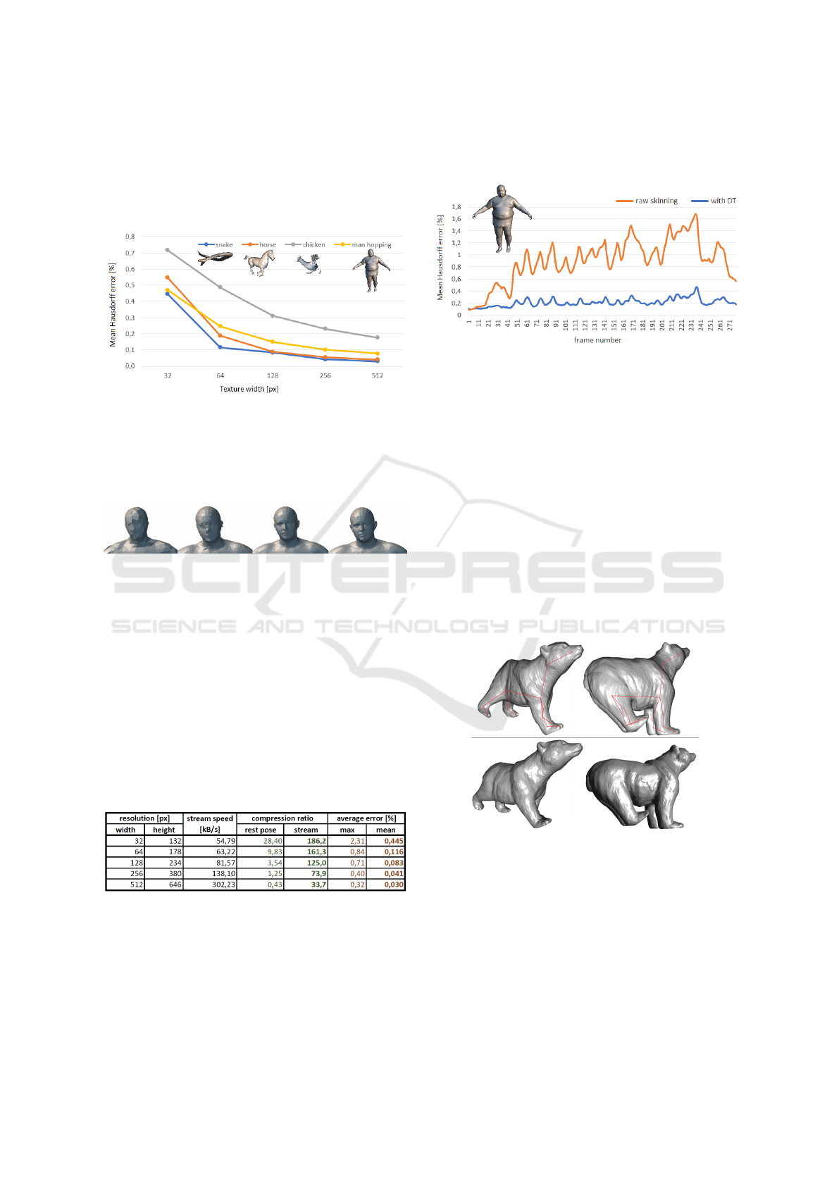
arbitrarily. The dependence of average reconstruction
error on texture width for different input animations is
shown in Figure 3. The error is computed as an aver-
age value of mean Hausdorff error through the whole
animation using MeshLab (Cignoni et al., 1998).
Figure 3: An evaluation of average reconstruction error de-
pending on texture resolution.
Visual comparison of reconstruction with differ-
ent levels of detail can be seen in Figure 4. All recon-
structions are flat-shaded.
Figure 4: Detail of reconstructed frame of SMPL Male an-
imation (Loper et al., 2015) with different levels of detail.
MCGIM texture width from left: 64, 128 and 256 pixels. In
the last image, there is the original input mesh.
Achieved compression ratios along with max and
mean average error (computed as normalized Haus-
dorff distance) are in Table 1. To compute the ratio,
the size of one original frame (340 kB for mesh in bi-
nary PLY format) is divided by the size of the same
frame in our representation.
Table 1: Achieved compression ratios along with aver-
age errors for the snake animation. In this table, there is
noted also the resolution of textures and the stream speed
which expresses the minimum needed bandwidth of real-
time streaming to achieve 30 FPS during the animation.
4.2 Impact of Difference Texture
The course of reconstruction error (mean Hausdorff
distance) during whole snake animation is in Figure 5.
Notice the improvement in quality when using the dif-
ferential texture as opposed to the case of a skinning
algorithm only. The lowest error is in the first frame
because it is used as bind-pose.
Figure 5: The course of mean Hausdorff distance during the
SMPL Male Hopping animation (Loper et al., 2015) recon-
structed from textures with resolution 128 x 190 pixels. The
average compression ratio in streaming was 405:1 for raw
skinning and 62:1 for case with DT.
4.3 Comparison with Alternative
Representations
If we use the Skeletex method (Madaras et al., 2018)
to represent the mesh animation, it would cause vis-
ible lightning artifacts, especially in animation with
extreme joints rotation. A visual comparison with our
method is in Figure 6. Notice the differences around
joints of the bear rear legs. Our method deforms the
rest-pose model smoothly since it uses skinning and
therefore has a C
1
continuity.
Figure 6: Comparison of extreme joints rotation performed
on bear model by Skeletex (top) and by our method (bot-
tom).
In Table 2, there is a numerical comparison
of our method with Skinning Mesh Animations
(SMA) (James and Twigg, 2005). We set the level
of detail for each animation independently so that the
reconstruction error was similar to the one in SMA.
Therefore, the compression ratio can be compared
easily. The error is computed as a Percent distortion,
similarly to the error in the SMA article with one edit.
GRAPP 2021 - 16th International Conference on Computer Graphics Theory and Applications
206
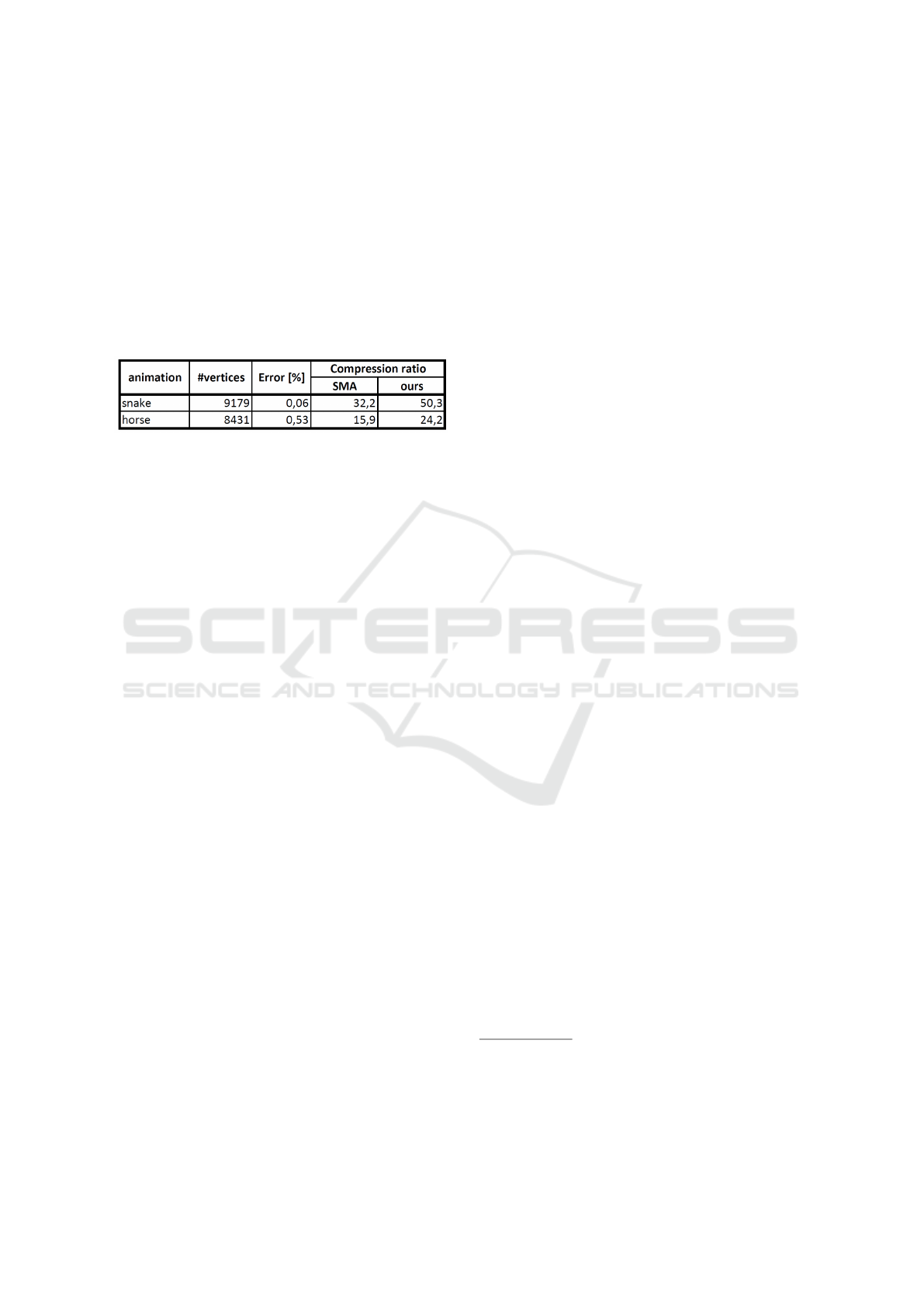
Since our method changes the geometry, the error is
computed as Hausdorff distance divided by the same
normalization factor as in the original metric. The im-
provement in the compression ratio is not big, how-
ever, note the ability to set the level of detail in our
method. If high quality is not needed (e.g. if the cam-
era in rendering is not close to the object), the LoD
can be lowered which causes a significant increase of
the compression ratio (see Table 1).
Table 2: Comparison of compression ratios with SMA
method.
5 DISCUSSION
The proposed animation representation enables com-
pression of the input mesh animation and real-time
rendering directly using the generated textures. How-
ever, along with the mesh animation, the skeleton and
skinning weights are required. For automatic extrac-
tion of them, some existing methods, like (James and
Twigg, 2005), can be used.
5.1 Advantages
The main advantage of the representation is param-
eterization properties. It is bijective in all cases due
to segmentation and the L
2
stretch is for most cases
less than 1.01, and that implicates high reconstruc-
tion quality which was confirmed within the evalua-
tion. Also, good compression ratios can be achieved
if a PNG encoding for rest-pose texture and MPEG
encoding for differential textures was used.
5.2 Limitations
The proposed representation is not suitable for anima-
tions that cannot be approximated by a skeleton, e.g.
building demolition or other animation with extreme
deformations. The vertices movement would have to
be captured just in the DT which is designed to con-
tain just little differences.
Another limitation is that the input meshes for all
animation frames need to have the same number of
vertices in the same order. This constraint makes it
hard to integrate our method with the fusion of some
moving object recorded by a 3D camera (Newcombe
et al., 2015). If the meshes do not satisfy this condi-
tion, our compression algorithm needs to be modified
to compare all pairs of input and reconstructed ver-
tices.
6 CONCLUSION
In this paper, a new method of mesh animation com-
pression was presented. Designed representation con-
sists of a skeleton and several textures where different
properties of a model in the rest pose are encoded.
Animation reconstructed from the representation was
evaluated and reasonable reconstruction quality was
measured. By setting the output texture resolution,
a compression ratio and the quality can be affected.
This trade-off can be affected also by changing the
video codec. In the evaluation, we used MPEG en-
coder. All textures consist of several disconnected
charts, nevertheless there were no visible holes or
cracks in the reconstructed mesh animation.
6.1 Future Work
There are several ideas to improve the proposed
method, but they are out of the scope.
During encoding surface differences in Differen-
tial Texture, they were multiplied by a manually esti-
mated scale so there is a limit, how big the difference
can be to be yet contained in the texture. However, it
could be automated and optimal value could be sent
for each frame. Furthermore, the user could specify if
he wants a higher compression ratio or rather higher
quality and the scale would be set according to this
requirement.
ACKNOWLEDGMENTS
We would like to express many thanks to Jason Smith
(the main author of the paper Bijective parameteriza-
tion with free boundaries) for help in the implemen-
tation of his method.
Mesh animations used in evaluation our method
are downloaded from different webpages
2
and
skinned rest poses from the SMA webpage
3
.
2
http://people.csail.mit.edu/sumner/research/deftransfer/
data.html (horse), http://www710.univ-lyon1.fr (snake),
http://graphics.cs.cmu.edu/projects/sma/textData/chicken
Crossing.zip (chicken)
3
http://graphics.cs.cmu.edu/projects/sma/textData
Mesh Animation Compression using Skinning and Multi-chart Displacement Texture
207

REFERENCES
Brice
˜
no, H. M., Sander, P. V., McMillan, L., Gortler, S., and
Hoppe, H. (2003). Geometry videos: a new represen-
tation for 3d animations. In Proceedings of the 2003
ACM SIGGRAPH/Eurographics symposium on Com-
puter animation, pages 136–146. Eurographics Asso-
ciation.
Cignoni, P., Rocchini, C., and Scopigno, R. (1998). Metro:
measuring error on simplified surfaces. In Computer
graphics forum, volume 17, pages 167–174. Wiley
Online Library.
Feng, W.-W., Kim, B.-U., Yu, Y., Peng, L., and Hart, J.
(2010). Feature-preserving triangular geometry im-
ages for level-of-detail representation of static and
skinned meshes. ACM Transactions on Graphics
(TOG), 29(2):1–13.
Floater, M. S. et al. (1997). Parametrization and smooth
approximation of surface triangulations. Computer
aided geometric design, 14(3):231–250.
Gu, X., Gortler, S. J., and Hoppe, H. (2002). Geometry im-
ages. In Proceedings of the 29th annual conference on
Computer graphics and interactive techniques, pages
355–361.
Jacobson, A. and Sorkine, O. (2011). Stretchable and
twistable bones for skeletal shape deformation. In
Proceedings of the 2011 SIGGRAPH Asia Confer-
ence, pages 1–8.
James, D. L. and Twigg, C. D. (2005). Skinning mesh
animations. ACM Transactions on Graphics (TOG),
24(3):399–407.
Karni, Z. and Gotsman, C. (2004). Compression of soft-
body animation sequences. Computers & Graphics,
28(1):25–34.
Kavan, L., Collins, S.,
ˇ
Z
´
ara, J., and O’Sullivan, C. (2007).
Skinning with dual quaternions. In Proceedings of
the 2007 symposium on Interactive 3D graphics and
games, pages 39–46.
Kavan, L. and
ˇ
Z
´
ara, J. (2005). Spherical blend skinning: a
real-time deformation of articulated models. In Pro-
ceedings of the 2005 symposium on Interactive 3D
graphics and games, pages 9–16.
Kry, P. G., James, D. L., and Pai, D. K. (2002). Eigen-
skin: real time large deformation character skinning
in hardware. In Proceedings of the 2002 ACM SIG-
GRAPH/Eurographics symposium on Computer ani-
mation, pages 153–159.
Lander, J. (1998). Skin them bones: Game programming
for the web generation. Game Developer Magazine,
5(1):10–18.
Le, B. H. and Hodgins, J. K. (2016). Real-time skeletal
skinning with optimized centers of rotation. ACM
Transactions on Graphics (TOG), 35(4):1–10.
Lee, P.-F., Kao, C.-K., Tseng, J.-L., Jong, B.-S., and Lin,
T.-W. (2007). 3d animation compression using affine
transformation matrix and principal component analy-
sis. IEICE TRANSACTIONS on Information and Sys-
tems, 90(7):1073–1084.
Loper, M., Mahmood, N., Romero, J., Pons-Moll, G., and
Black, M. J. (2015). SMPL: A skinned multi-person
linear model. ACM Trans. Graphics (Proc. SIG-
GRAPH Asia), 34(6):248:1–248:16.
Madaras, M., Rie
ˇ
cick
`
y, A., Mes
´
aro
ˇ
s, M., Stuchl
´
ık, M.,
and Piovar
ˇ
ci, M. (2018). Skeletex: Skeleton-texture
co-representation for topology-driven real-time inter-
change and manipulation of surface regions. In Com-
puter Graphics Forum, volume 37, pages 325–336.
Wiley Online Library.
Mamou, K., Zaharia, T., and Preteux, F. (2006). Multi-
chart geometry video: A compact representation for
3d animations. In Third International Symposium on
3D Data Processing, Visualization, and Transmission
(3DPVT’06), pages 711–718. IEEE.
Newcombe, R. A., Fox, D., and Seitz, S. M. (2015). Dy-
namicfusion: Reconstruction and tracking of non-
rigid scenes in real-time. In Proceedings of the IEEE
conference on computer vision and pattern recogni-
tion, pages 343–352.
Payan, F., Kamoun, A., and Antonini, M. (2008). Remesh-
ing and spatio-temporal wavelet filtering for 3d an-
imations. In 2008 IEEE International Conference
on Acoustics, Speech and Signal Processing, pages
1081–1084. IEEE.
Rabinovich, M., Poranne, R., Panozzo, D., and Sorkine-
Hornung, O. (2017). Scalable locally injective
mappings. ACM Transactions on Graphics (TOG),
36(4):1.
Rockafellar, R. T. and Wets, R. J.-B. (2009). Variational
analysis, volume 317. Springer Science & Business
Media.
Sander, P. V., Gortler, S., Snyder, J., and Hoppe, H. (2002).
Signal-specialized parameterization.
Sander, P. V., Snyder, J., Gortler, S. J., and Hoppe, H.
(2001). Texture mapping progressive meshes. In Pro-
ceedings of the 28th annual conference on Computer
graphics and interactive techniques, pages 409–416.
Sander, P. V., Wood, Z. J., Gortler, S., Snyder, J., and
Hoppe, H. (2003). Multi-chart geometry images.
Sattler, M., Sarlette, R., and Klein, R. (2005). Simple and
efficient compression of animation sequences. In Pro-
ceedings of the 2005 ACM SIGGRAPH/Eurographics
symposium on Computer animation, pages 209–217.
Smith, J. and Schaefer, S. (2015). Bijective parameteri-
zation with free boundaries. ACM Transactions on
Graphics (TOG), 34(4):1–9.
Tarini, M., Hormann, K., Cignoni, P., and Montani, C.
(2004). Polycube-maps. ACM transactions on graph-
ics (TOG), 23(3):853–860.
Tutte, W. T. (1960). Convex representations of graphs.
Proceedings of the London Mathematical Society,
3(1):304–320.
Usai, F., Livesu, M., Puppo, E., Tarini, M., and Scateni,
R. (2015). Extraction of the quad layout of a triangle
mesh guided by its curve skeleton. ACM Transactions
on Graphics (TOG), 35(1):1–13.
Yoshizawa, S., Belyaev, A., and Seidel, H.-P. (2004). A
fast and simple stretch-minimizing mesh parameteri-
zation. In Proceedings Shape Modeling Applications,
2004., pages 200–208. IEEE.
GRAPP 2021 - 16th International Conference on Computer Graphics Theory and Applications
208
