Precise Upright Adjustment of Panoramic Images
Nobuyuki Kita
TICO-AIST Cooperative Research Laboratory for Advanced Logistics (ALLAB),
National Institute of Advanced Industrial Science and Technology (AIST), Tsukuba, Japan
Keywords: Panoramic, Equirectangular, Upright Adjustment, Vertical Lines, Omnidirectional, 360 Degree, Spherical.
Abstract: An equirectangular format is often used when an omnidirectional image taken by a 360° camera is expanded
into a single image, which is referred to as a panoramic image. If an omnidirectional image is expanded into
a panoramic image using the upward direction of the inclined camera, the image may look unstable and “wavy.”
It is important to correct the inclination using the zenith direction as a reference; this task is called "upright
adjustment." In this paper, we propose a method for upright adjustment by estimating the inclination of a
camera in a wavy panoramic image using vertical lines in the environment, e.g., indoors or outdoors near a
building. The advantage of the proposed method is that 3D straight lines are detected with high accuracy and
high speed directly from a panoramic image without passing through a spherical image. Experimental results
of upright adjustment of the wavy panoramic images taken in multiple places show that the proposed method
is accurate and can be applied in a wide range of indoor and outdoor scenarios.
1 INTRODUCTION
Many 360° cameras are on the market, and it has
become easy to obtain omnidirectional images, which
are used for applications such as personal and SNS
viewing, VR use, and real-estate advertisement
(Ricoh 2020). In the 1980s, in robotics and related
fields, omnidirectional cameras were made by hand.
The estimation of self-position and posture as well as
three-dimensional (3D) reconstruction of the
environment were carried out using these images
(Yagi 1999). At present, research using a lightweight,
high-resolution commercial 360° camera for mobile-
robot vision is ongoing (Payá, Gil et al. 2017;
Jayasuriya, Ranasinghe et al. 2020).
An omnidirectional image may be regarded as a
storage of color (or intensity) information in the
whole viewing direction from the origin, and it is
expanded into various 2D formats and projected on a
display device or printed according to the application.
For example, when the information is displayed on an
HMD for VR, partial information about the viewing
direction is converted into a perspective projection
and displayed on the HMD.
When information in all directions is displayed in
one image, it is necessary to expand a sphere into a
plane, and a common method is to expand the sphere
to an equirectangular format, which is referred to as a
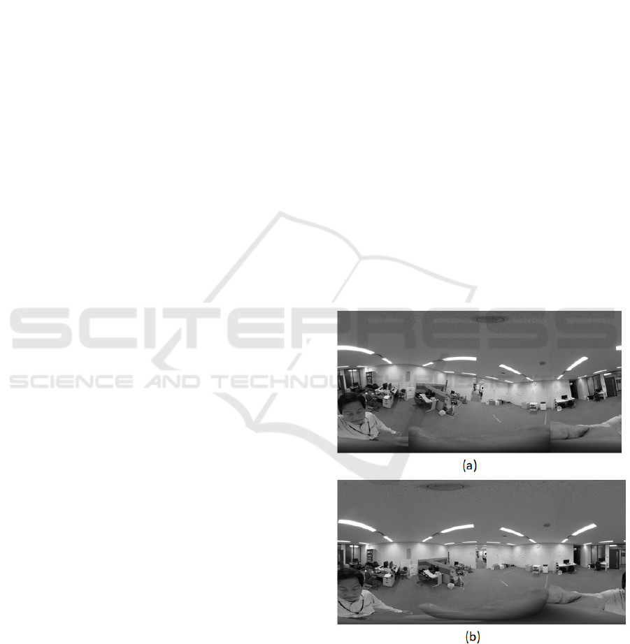
Figure 1: Example of a panoramic image before and after
inclination correction.
panoramic image. In Figure 1(a), the image is
constructed using the upward direction of the inclined
camera, and the image looks unstable and “wavy.” In
contrast, Figure 1(b) is a panoramic image
Kita, N.
Precise Upright Adjustment of Panoramic Images.
DOI: 10.5220/0010242600990111
In Proceedings of the 16th International Joint Conference on Computer Vision, Imaging and Computer Graphics Theory and Applications (VISIGRAPP 2021) - Volume 4: VISAPP, pages
99-111
ISBN: 978-989-758-488-6
Copyright
c
2021 by SCITEPRESS – Science and Technology Publications, Lda. All rights reserved
99

constructed using the zenith direction obtained by
knowing the inclination of the camera at the time of
image capture.
Even when directly viewing an omnidirectional
image with an HMD or similar device, if the camera
inclination is not corrected, an image with an
inclination that does not match that of the HMD is
displayed, so inclination correction is important.
Therefore, many studies have investigated image
display in VR without discomfort (Jung, Kim et al.
2017; Jeon, Jung et al. 2018; Jung, Lee et al. 2019).
When omnidirectional images are used for the
vision of mobile robots such as AGVs and UAVs,
many studies convert them into panoramic images.
For AGV applications, many studies use yaw as the
only camera pose degree of freedom (DOF) (Milford
and Wyeth 2010; Liu, Pradalier et al. 2013). In
contrast, in UAVs, the camera posture has three
DOFs, and the roll and pitch of the camera must be
estimated (Demonceaux, Vasseur et al. 2007; Natraj,
Ly et al. 2013). Even in an AGV, three DOFs of the
camera attitude must be considered to enable the
application to handle running surfaces that are not flat
(Bosse, Rikoski et al. 2002). If the camera tilt is
estimated and an inclination corrected panoramic
image is obtained, a method using yaw only can be
employed. However, the inclination correction must
be more accurate than that required in VR.
The accuracy of inclination correction depends on
the accuracy of camera inclination estimation at the
time of image capture. Some methods use
information from external sensors such as IMUs,
whereas others use image analysis to determine the
zenith direction. The latter approach can be further
divided into methods that utilize vertical or horizontal
lines in the environment and those that do not.
In this paper, we use longitudinally parallel lines
existing in the environment without the help of an
external sensor. Many methods have been proposed
for estimating the inclination of a camera by detecting
straight lines in the environment using a
omnidirectional image as input. However, most
detect 3D straight lines by detecting the great circles
on a spherical image, and no research has detected
straight lines in the environment directly from a
panoramic image. Here, 3D straight lines in the
longitudinal direction are directly detected from the
panoramic image before correction, and the azimuth
and inclination angle are estimated with high
accuracy. For this purpose, a method of performing a
special Hough transform of an edge point on a
panoramic image is analytically derived. Next, a
method for selecting parallel lines from the detected
3D lines is obtained analytically. Moreover, it is
shown that the inclination in the camera coordinate
system of the parallel lines can be obtained. Unless it
is a special environment, a longitudinally parallel line
group is a vertical line group, and this is the zenith
direction. Thus, we obtain fast and accurate method
for correcting the inclination of the camera.
The contributions of this paper are as follows.
A formula for the curve on a panoramic image of
a longitudinal 3D line in the environment is
derived.
A special Hough transform of the edge points in
the longitudinal direction based on the derived
equation realizes stable 3D line detection.
The constraints of the projected image of a group
of longitudinal straight lines are obtained
analytically.
The inclination of the camera is estimated
robustly and accurately by RANSAC (Fischler,
Martin et al. 1981) processing based on the
constraints.
Section 2 reviews existing research on camera tilt
correction, Section 3 explains the proposed method,
Section 4 describes the implementation including
speedup, and Section 5 analyzes the experimental
results. Section 6 discusses differences between this
work and similar studies, and Section 7 concludes
with a discussion of future work.
2 RELATED WORK
Studies have been conducted for many years to
estimate the inclination of a camera at the time of
image capture by analyzing the image itself to
generate an image with the correct inclination
(Cipolla, Robertson et al. 1999; Gallagher 2005; Lee,
Shechtman et al. 2013). Lee et al. (2013) call this
"upright adjustment," and we follow their lead. The
methods for upright adjustment can be divided into
two groups: methods that do and do not use the
vertical and horizontal lines in the environment. In
this section, we focus on studies that use
omnidirectional images as input.
2.1 Methods using 3D Lines
Based on the Manhattan world assumptions
(Coughlan and Yuille 1999; Zhang, Lu et al. 2016)
and the Atlanta world assumptions (Schindler and
Dellaert 2004; Joo, Oh et al. 2018), which state that a
group of parallel lines existing indoors or in the
suburbs is generally a group of vertical lines or a
group of horizontal lines, many studies have been
conducted to estimate the inclination of a camera by
VISAPP 2021 - 16th International Conference on Computer Vision Theory and Applications
100

detecting a vanishing point from a projection image
of a group of lines.
Wang et al. (2003) projected an omnidirectional
image onto a unit sphere, detected the edge points and
their slopes, voted for a straight line cutting Z = 1 for
each edge point, and the position of the peak score
was considered the zenith direction.
Using the orthogonality of multiple vanishing
points as a constraint, Bazin et al. (2012) stably
detected the vanishing points of parallel line groups
in the environment. These groups are based on the
detection of the great circle on the unit sphere for
individual straight line detection.
Jung et al. (2017) converted a panoramic image
into a Cubemap to detect straight line segments. After
separating the lines into horizontal and vertical
directions using the Hough transform of the line-
segment end points in spherical coordinates with the
line-segment length as a weight, they find the great
circles in the horizontal and vertical directions. Next,
the intersection of the great circle in the horizontal
direction is obtained as a vector to the horizontal
vanishing point. The vector to the zenith direction is
estimated by orthogonality to the normal vector of the
great circle in the vertical direction and the vector to
the horizontal vanishing point. Since they use both
vertical and horizontal lines in the environment, the
estimation can be obtained even if there are no
vertical lines in the environment. Since a great circle
detected on the basis of both ends of the short line
segment contains considerable error, repetition is
required to reduce the inclination estimation error.
Kawai (2019) corrected the inclination of the
camera based on the knowledge that the projection
image of the 3D vertical line on the panoramic image
can be detected as a line segment in the direction
slightly inclined from the vertical near the vertical
center line of the image. Moreover, the relationship
between the horizontal position intersecting the
vertical center line of the image and the tilt can be
approximated by a sine wave, which yields the
inclination of a camera.
2.2 Methods Not using 3D Lines
In (Demonceaux, Vasseur et al. 2006), to detect the
attitude of a UAV, a horizontal line was detected by
separating the omnidirectional image into
sky/ground; the inclination of the camera was the
direction perpendicular to the horizontal line.
Jung et al. (2019) proposed a method using deep
learning without using a group of straight lines or a
horizontal line. From the SUN360 dataset (Xiao,
Ehinger et al. 2012), which consists of 67,000 upright
panoramic images of various scenes, panoramic
images appropriately inclined in an arbitrary direction
were synthesized through spherical projection. Three
kinds of CNNs were trained using these images, and
the results were compared. The average estimation
error was 5°.
Jeon et al. (2018) derived the relationship between
the 2D rotation of a small rectangular area near the
vertical center lines of the panoramic image and the
3D rotation of the camera. They further derived the
periodic relationship between the amount of 2D
rotation and lateral position. The 2D rotation of the
small region was estimated by a trained CNN, and the
3D tilt of the camera was estimated by the RANSAC
method with the periodic function as a constraint. An
average error of 1.3°, including cases without straight
or horizontal lines, was achieved experimentally.
3 UPRIGHT ADJUSTMENT
METHOD
The proposed method detects a group of longitudinal
3D straight lines from a panoramic image taken
indoors or outdoors adjacent to a structure and
estimates the inclination of the camera. In similar
methods, a 3D straight line is detected as a great circle
after conversion into a spherical projection, but in this
method, a 3D straight line is detected with high
accuracy directly from a panoramic image. For this
purpose, a new Hough transform is proposed.
3.1 Coordinate System Definitions
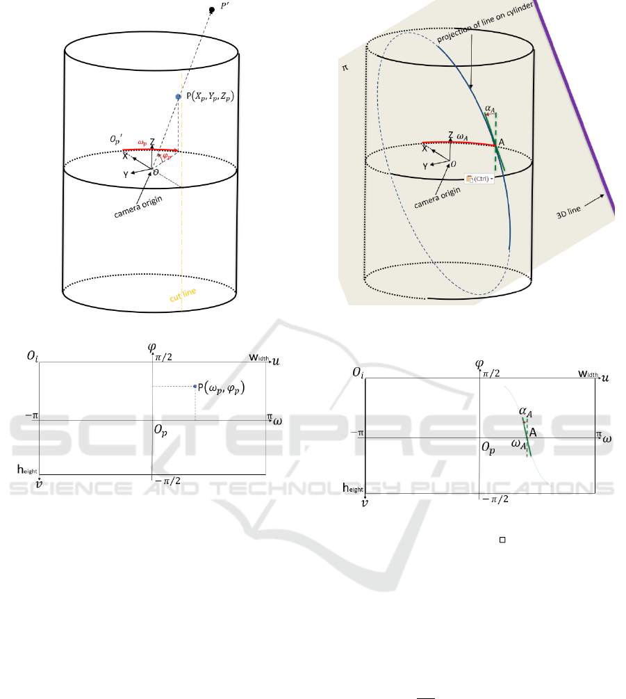
Figure 2(a) shows an omnidirectional camera
coordinate system OXYZ and a panoramic projection
cylinder, and Figure 2(b) shows a panoramic
coordinate system 𝑂
𝜔𝜑 and a panoramic image
coordinate system 𝑂
𝑢𝑣. The panoramic projection
plane is a cylindrical plane with the camera Z axis as
a central axis, and a point in 3D space 𝑃
′
is projected
onto a point P𝑋
,𝑌
,𝑍
on the cylindrical plane. For
convenience, the radius of the cylindrical surface is 1.
Then, 𝑋
+𝑌
=1 and −∞ <𝑍
<∞.
The cylindrical surface is cut in a direction
parallel to the Z axis and expanded in a 2D plane to
form the panoramic coordinate system. For
convenience, if the cut position is along the negative
X axis, the origin of panoramic coordinate system 𝑂
is position 𝑂
, where the cylindrical surface and the
X-axis intersect. Moreover, horizontal axis ω is a
horizontal distance on the cylindrical surface from
Precise Upright Adjustment of Panoramic Images
101
(a)
(b)
Figure 2: (a) Omnidirectional camera coordinate system
OXYZ and a panoramic projection cylinder. (b) Panoramic
coordinate system 𝑂
𝜔𝜑 and panoramic image coordinate
system 𝑂
𝑢𝑣.
𝑂
′
and indicates an azimuth angle, −π <ω <π.
Vertical axis φ of the panoramic coordinate system
corresponds to the elevation angle in the camera
coordinate system, −𝜋 2
⁄
<φ <𝜋2
⁄
.
The relationship between the panoramic image
coordinates
(
𝑢,𝑣
)
and panoramic coordinates
(
𝜔,𝜑
)
is as follows for an image width × height in size:
ω=
(
𝑢−𝑤𝑖𝑑𝑡ℎ2
⁄
+0.5
)
×2𝜋𝑤𝑖𝑑𝑡ℎ
⁄
φ=
(
ℎ𝑒𝑖𝑔ℎ𝑡 2
⁄
−𝑣+0.5
)
× 𝜋 ℎ𝑒𝑖𝑔ℎ𝑡
⁄
3.2 Basic Principles
As shown in Figure 3, the projection curve of a
longitudinal 3D straight line on the cylindrical surface
is a part of the outline of the cross section in which
Figure 3: Projection curve of the longitudinal 3D straight
line on the cylindrical surface.
Figure 4: 𝜔
and 𝛼
on the panoramic image.
the 3D plane π including the camera center and the
3D straight line cuts the cylinder (blue solid line in
Figure 3).
Let the point where the projection curve on the
cylindrical surface intersects the XY plane (Z = 0) be
A, the azimuth angle be 𝜔
, and the inclination from
the Z axis of the tangent of the projection curve at
point A be 𝛼
. It can be seen that the plane π
including the 3D straight line is inclined by 𝛼
degrees around 𝑂𝐴
which is the vector indicating the
azimuth angle 𝜔
.
Figure 4 shows 𝜔
and 𝛼
on a panoramic image.
The blue curved line is a 2D projection curve obtained
by developing a 3D projection curve on a cylindrical
surface onto a panoramic image. Here, the
intersection point with the 𝜔 axis is A, 𝜔
is obtained
as the azimuth angle of point A, and 𝛼
is obtained as
the angle between a tangent of the 2D projection
curve at point A and theφ axis.
VISAPP 2021 - 16th International Conference on Computer Vision Theory and Applications
102
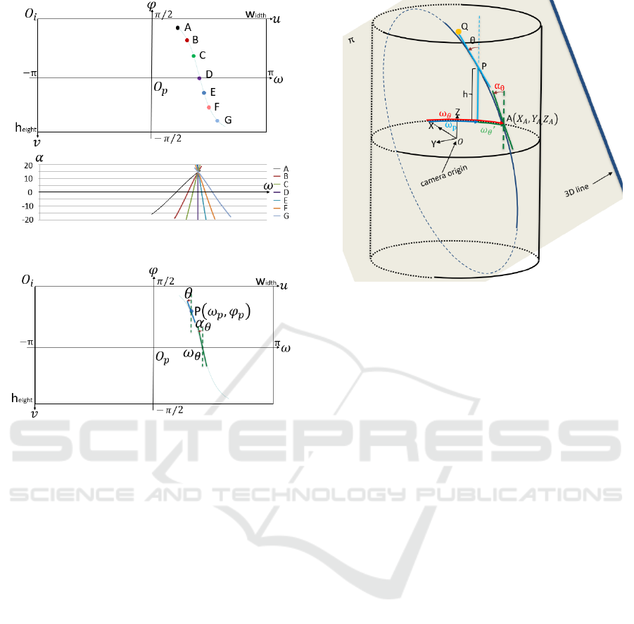
Figure 5: Example of special Hough transform.
Figure 6: (𝜔𝜃,𝛼𝜃) must be obtained from P(𝜔𝑃,𝛼𝑃) and 𝜃.
That is, if
(
𝜔,𝛼
)
can be detected for a 2D
projection curve of a 3D straight line on a panoramic
image, the inclination or normal direction of the 3D
plane π including the 3D straight line can be
obtained.
If two parallel lines exist in the 3D space and
(
𝜔,𝛼
)
can be obtained for each of the projected
curves on the panoramic image, the direction vector
of the parallel line is a vector orthogonal to the normal
direction of the two 3D planes.
3.3 Detection of a 3D Straight Line
from a Panoramic Image
The detection of 3D straight lines from a projected
image generally consists of two steps. First, edge
points are detected on the image by an edge detector
such as Canny (Canny, John 1986). Next, 3D lines are
detected by grouping the edge points in the parameter
space by a Hough transform or the like.
For a perspective projection image, since a
projection of a 3D straight line is a 2D straight line, it
can be obtained by a Hough transform in which the
straight line of every inclination passing through the
edge point is voted in a parameter space
(
𝜌,𝜃
)
Figure 7:
(
𝜔
,𝛼
)
from P and 𝜃 in the camera coordinate
system.
representing the straight line (Illingworth, John et al.
1988).
In the case of a panoramic image, as shown in
Figure 4, the projection of a 3D straight line is a curve,
and we represent this curve by one set of 𝜔 and 𝛼.
Then, a 3D straight line is detected by the Hough
transform, which votes in the
(
𝜔,𝛼
)
space with
respect to the projection curve of every inclination
passing through the edge point detected on the
panoramic image. Figure 5 shows an example of such
a Hough transform. Each of the edge points A from G
on the panoramic image is converted to a curved line
in the parameter space. Thus, when the edge points lie
on the projection curve of a 3D straight line, many
votes are collected at one point on the parameter
space. To do this, as shown in Figure 6, it is necessary
to obtain
(
𝜔
,𝛼
)
when the projection curve passes
through edge point P
(
𝜔
,𝛼
)
with an inclination of
𝜃 °.
We derive the calculation of
(
𝜔
,𝛼
)
from
(
𝜔
,𝛼
)
and 𝜃 in the camera coordinate system, as
shown in Figure 7. Edge point P is located at azimuth
𝜔
and height h=tan𝜑
on the panoramic
cylindrical surface. Note that 𝜔
=𝜔
+𝜔
′
and
only 𝜔
′
depends on h and 𝜃. Hereafter, it is
assumed that edge point P is in the X-axis direction,
that is, 𝜔
=0. The coordinates of point P in the
camera coordinate system are (1, 0, h). Next, let a
point on a straight line passing through an edge point
P on the plane X = 1, where the angle formed by the
Z axis is 𝜃, be denoted by Q (1, tan 𝜃, h + 1). Here,
cutting plane π passes through the origin (0,0,0),
Precise Upright Adjustment of Panoramic Images
103
point P (1,0, h), and point Q (1, tan 𝜃, h + 1). The
equation ofπ is
ℎ𝑋 +
(
1tan𝜃
⁄)
𝑌−𝑍=0
The intersection between cutting plane π and the
cylindrical surface is
𝑋
+𝑌
=1
and the X- and Y-coordinates are obtained by the
following formulas using Z as a parameter.
𝑋
=
ℎ
(
tan𝜃
)
1+ℎ
(
tan𝜃
)
𝑍
±
−
(
tan𝜃
)
𝑍
+ℎ
(
tan𝜃
)
+1
1+ℎ
(
tan𝜃
)
𝑌
=
tan𝜃
1+ℎ
(
tan𝜃
)
𝑍
±
−ℎ
(
tan𝜃
)
𝑍
+ℎ
(
tan𝜃
)
(
1+ℎ
(
tan𝜃
)
)
1+ℎ
(
tan𝜃
)
Let A 𝑋
,𝑌
,
𝑍
be the coordinates of a position
where
(
𝜔,𝛼
)
should be obtained when assuming
𝜔
=
0
. Since 𝑍
=0,
𝑋
=±
1
1+ℎ
(
tan𝜃
)
𝑌
=±
ℎ
(
tan𝜃
)
1+ℎ
(
tan𝜃
)
Therefore, 𝜔
′
in Figure 7 is
𝜔
=tan
𝑌
𝑋
=tan
(
ℎtan𝜃
)
As for 𝛼
, because
∆𝑋
=
𝜕𝑋
𝜕𝑍
(
0
)
=
ℎ
(
tan𝜃
)
1+ℎ
(
tan𝜃
)
∆𝑌
=
𝜕𝑌
𝜕𝑍
(
0
)
=
tan𝜃
1+ℎ
(
tan𝜃
)
then
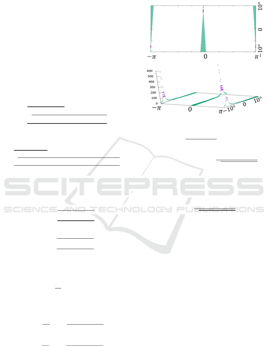
Figure 8: Voting result for the edge points on the projection
curve when h = 0.0 and 𝜃 = 7.7°.
α
=tan
∆𝑋
+∆𝑌
=tan
tan𝜃
1+ℎ
(
tan𝜃
)
Next, we have
ω
=𝜔
+tan
(
ℎtan𝜃
)
(1)
α
=tan
tan𝜃
1+ℎ
(
tan𝜃
)
(2)
When an edge point exists at coordinates (u, v) in the
panoramic image coordinate system,
h=tan
(
ℎ𝑒𝑖𝑔ℎ𝑡 2
⁄
−𝑣+0.5
)
× 𝜋 ℎ𝑒𝑖𝑔ℎ𝑡
⁄
(3)
𝜔
=
(
𝑢−𝑤𝑖𝑑𝑡ℎ2
⁄
+0.5
)
×2𝜋𝑤𝑖𝑑𝑡ℎ
⁄
(4)
Because
(
𝜔
,𝛼
)
can be calculated by Equations
(1)–(4) from (u, v) and 𝜃, one vote is cast to the
corresponding bin in
(
𝜔,𝛼
)
space.
The range and granularity of
(
𝜔,𝛼
)
and θ may
be determined from the desired range and accuracy of
the camera inclination estimation. The aim of the
proposed method is to estimate camera inclination
with high accuracy and the camera is assumed to
incline in an arbitrary direction. Then the range of ω
is −π <ω <πand ωis divided into the size of the
image width. The upper limit of the camera
inclination angle is set to 10° or 20° in this study, and
the ranges of α and 𝜃 are divided into steps of 0.1°.
Figure 8 shows the voting result for the edge
points on the projection curve when h = 0.0 and 𝜃 =
VISAPP 2021 - 16th International Conference on Computer Vision Theory and Applications
104
7.7°. A green dot indicates a bin with 1–99 votes, and
a purple dot indicates a bin with >100 votes. The bin
with the maximum in the purple region around ω= 0
is α = 7.7° at ω = 0.0°, and the bin with the
maximum in the purple region around ω= −π is α
= −7.7° at ω = −π°. In other words, the azimuth
and inclination degree of the 3D plane including a 3D
longitudinal line can be detected with an accuracy of
0.1° or less by position
(
𝜔,𝛼
)
at which the voting
score is maximum within a region that exceeds a
threshold value.
3.4 Robust Detection of Zenith
Direction
As mentioned in Section 3.2, the inclination of a
parallel 3D line in the camera coordinate system can
be estimated if two 3D parallel lines can be detected
in different directions from the viewpoint of the
camera. However, there are some lines that are not
parallel in the usual environment. In Section 3.3,
(
𝜔,𝛼
)
of the projection curve is derived for a 3D
straight line, but
(
𝜔,𝛼
)
is also obtained for a straight
line that is not parallel. Therefore, to correctly
estimate the direction of the parallel 3D line group
from the
(
𝜔,𝛼
)
group detected from the panoramic
image, the property of the projection curve of a
parallel 3D line group is derived so that outliers can
be eliminated.
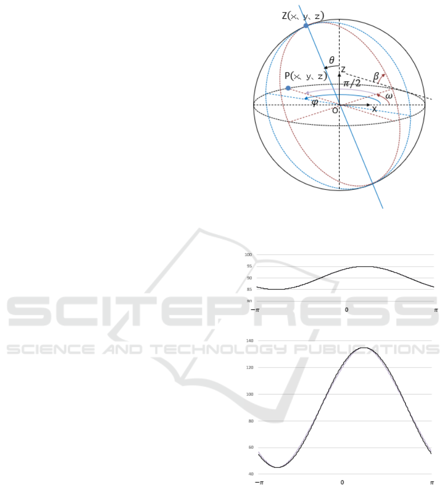
As shown in Figure 9, when the azimuth and
inclination angles of the parallel 3D line group in the
camera coordinate system are 𝜑 and 𝜃, respectively
the coordinates of point Z are
Z=
(
sin𝜃 cos𝜑,sin𝜃sin𝜑 ,cos𝜃
)
The 3D plane including each of the parallel lines and
the camera origin rotates around OZ. Angle β at the
position rotated by 𝜔 from the X direction is equal to
the angle formed by OZ and OP with P being the
position advanced by 𝜋/2 from 𝜔. Here, the
coordinates of P are
P=
(
−sin𝜔,cos𝜔,0
)
Hence,
β=cos
(
𝑍∙𝑃
)
=cos
(
sin𝜃 sin𝜑 cos𝜔
− sin𝜃 cos𝜑 sin𝜔
)
Figure 9: Property of the projection curve of a 3D parallel
line group.
(a)
(b)
Figure 10: Curves when the azimuth angle is 130º and the
inclination angle is (a) 5º and (b) 45º.
For example, Figure 10(a) shows the curve when the
azimuth angle is 130º and the inclination angle is 5º.
The curve is nearly equal to the curve
𝛽=𝜃×sin
(
𝜔−𝜑
)
+𝜋2
⁄
Precise Upright Adjustment of Panoramic Images
105
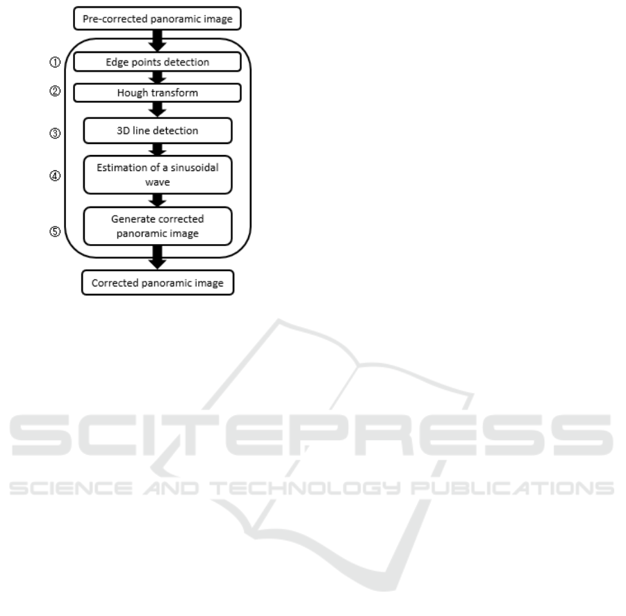
Figure 11: Proposed upright adjustment.
The absolute difference is not more than 0.003°. For
larger inclination angles, when the azimuth angle is
130° and the inclination angle is 45°, Figure 10(b)
shows the curve, and the maximum absolute
difference is about 1.9°. However, there is no
difference between the phase and amplitude. Here,
because α = π / 2 − β of
(
𝜔,𝛼
)
, representing the
projection image of the parallel 3D line, 𝜔 and 𝛼 of
the projection curve group of the parallel 3D line
group on the panoramic image may be on a sine wave.
Therefore, by applying the sinusoidal wave to the
(
𝜔,𝛼
)
group detected from the panoramic image, the
azimuth angle φ and inclination angle 𝜃 of the
parallel straight line group can be obtained as the
phases and amplitudes.
4 IMPLEMENTATIONS
Figure 11 shows a flow chart of the proposed process
for upright adjustment.
First, a binary edge image is created from a
panoramic image by the Canny function from
OpenCV. Because the projection curve of a
longitudinal 3D straight line has a direction close to
the vertical except at the top and bottom of the
panoramic image, even if the camera is tilted to some
extent, the horizontal continuous edge points are
removed.
Next, each edge point (u, v) is voted in
(
𝜔,𝛼
)
space while changing 𝜃. In this implementation, −π
<ω <π is divided into width to handle the vertical
and horizontal vibrations of the camera. The ranges
of 𝜃 and α and step size are given by the parameters
maxangle and sampangle, respectively, considering
the desired range and accuracy of the camera tilt. In
addition, because the upper area of a panoramic
image is occupied by a ceiling and the sky and the
lower area by a floor or road surface, only edge points
within the parameter vertarea from the vertical center
are considered. As Figure 4 shows, 𝜔
′
,𝛼 depends
on h and 𝜃 but not on 𝜔
. Therefore, a conversion
table from (h, 𝜃) to 𝜔
′
,𝛼 is created in advance,
and it is used to more quickly obtain
(
𝜔,𝛼
)
from (u,
v) andθ.
A 3D straight line is detected by determining the
position with the maximum value in each column of
a bin that has more votes than threshold pthresh in
(
𝜔,𝛼
)
space. However, if there are consecutive
maximum values in the column direction, only the
position
(
𝜔,𝛼
)
with the maximum number of votes is
adopted. The
(
𝜔,𝛼
)
, obtained as described above,
includes non-parallel lines. To perform a robust
estimation, at the next RANSAC processing, a certain
number of straight line candidates are required, and
the threshold of the number of candidates is given by
parameter topthresh. When a given pthresh may not
yield more than topthresh line candidates, pthresh is
reduced in increments of parameter dec until more
than topthresh line candidates are obtained.
With respect to the set of
(
𝜔,𝛼
)
greater than
topthresh, seednum pieces are randomly selected to
obtain a sinusoidal wave, and the candidates that
deviate in the α direction from the sinusoidal wave
less than parameter thinlier are processed by
RANSAC as inliers, thereby robustly obtaining a
sinusoidal wave.
The direction of the parallel straight line group is
calculated from the phase and amplitude of the
obtained sine wave, and the panoramic image is
converted using this as the zenith direction. The
inclination-corrected panoramic image is then output.
In addition, steps ② and ⑤ in Figure 11 were
parallelized with OpenMP to increase speed.
5 EXPERIMENTAL RESULTS
5.1 Results of Upright Adjustment
Figures 12(a)–(f) show successful examples of
upright adjustment. In each subfigure, the top row
shows the panoramic image before correction. The
next row shows the edge image in the considered
VISAPP 2021 - 16th International Conference on Computer Vision Theory and Applications
106
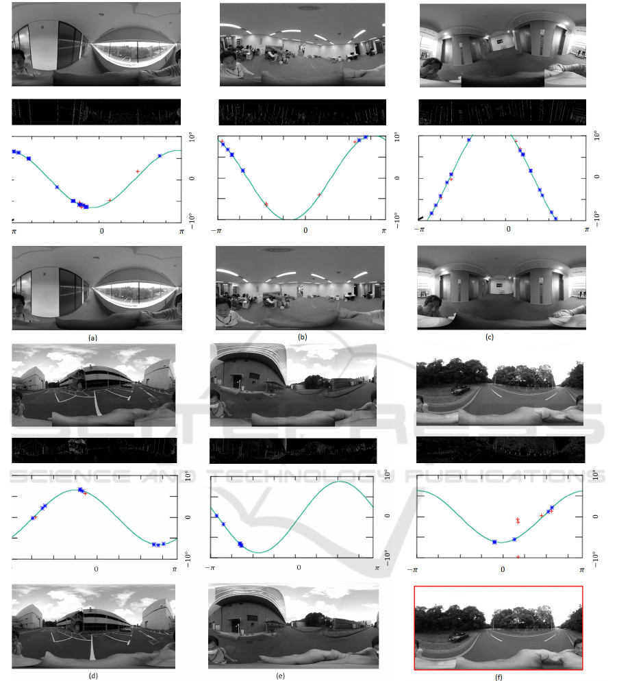
Figure 12: Successful examples of upright adjustment.
range, and the row below shows
(
𝜔,𝛼
)
space, where
blue indicates inliers, red indicates outliers, and the
green line is the sine curve obtained by RANSAC.
The bottom rows show the corrected panoramic
image. The inputs were 3840 × 1920 panoramic
images, Hough transformed with maxangle = 10.0,
sampangle = 0.1, and vertarea = 300; detected with
pthresh = 150, topthresh = 10, and dec = 10; and
corrected based on the phase and amplitudes of the
sinusoidal waves obtained by RANSAC with
seednum = 3 and thinlier = 2.
Because Figure 12(a) shows a corridor and a large
number of vertical lines exist near the camera, the
upright adjustment can be performed stably. Figure
12(b) shows an image from the center of a room, in
which the 3D vertical lines on the wall are projected
Precise Upright Adjustment of Panoramic Images
107
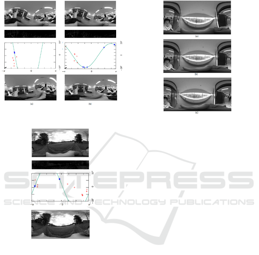
Figure 13: Case in which the camera inclination is larger
than maxangle.
Figure 14: Failed examples of upright adjustment.
as short 2D curves, and the inclination can be
corrected although the number of detected lines is
smaller than that for the corridor. Figure 12(c) was
taken in an elevator hall. It can be seen that the camera
is tilted more than maxangle degrees, so almost half
of the 3D lines are not detected, but the out-of-range
camera tilt has been detected. As shown in Figures
12(d) and (e), the inclination correction can be
performed stably outside a building. Figure 12(f)
shows an image of a road far from buildings, but the
inclination can be corrected by detecting street lights
and signs and decreasing pthresh. The red line in the
frame of the corrected image is (100-pthresh) thick,
which visualizes the uncertainty of the estimation.
Figure 15: Comparison with the result obtained by the
application of a camera manufacturer.
In Figure 13(a), because the camera is severely
inclined, most of the projected curves of the 3D
vertical lines are not detected with an inclination of
more than maxangle, and since pthresh is reduced to
120, many incorrect lines are detected and the
correction fails. Figure 13(b) shows a result of upright
adjustment with a maxangle of 20°. When pthresh
is 150, a straight line greater than topthresh can be
detected, and the zenith direction can be correctly
estimated even if an incorrect straight line is included
in the RANSAC processing.
Figure 14 is an image at the edge of a field, and
the zenith estimation fails because of the influence of
a tree that extends obliquely across the few vertical
lines that can be observed.
Figure 15(a) is a panoramic image before
correction, Figure 15(b) is the result of adjustment
obtained by the proposed method, and Figure 15(c) is
the result obtained by an application from a camera
manufacturer. The difference in correction accuracy
can be seen around the door of the room.
A sample movie is also attached; the lower left is
input, upper left is the image corrected by the
proposed method with maxangle = 10, the upper right
is the image corrected by the proposed method with
maxangle = 20 and lower right is the image corrected
by the manufacturer’s application.
5.2 Estimation Accuracy
To evaluate the accuracy of camera inclination
estimation, it is almost impossible to obtain ground
truth with an accuracy of 0.1° because recent
VISAPP 2021 - 16th International Conference on Computer Vision Theory and Applications
108
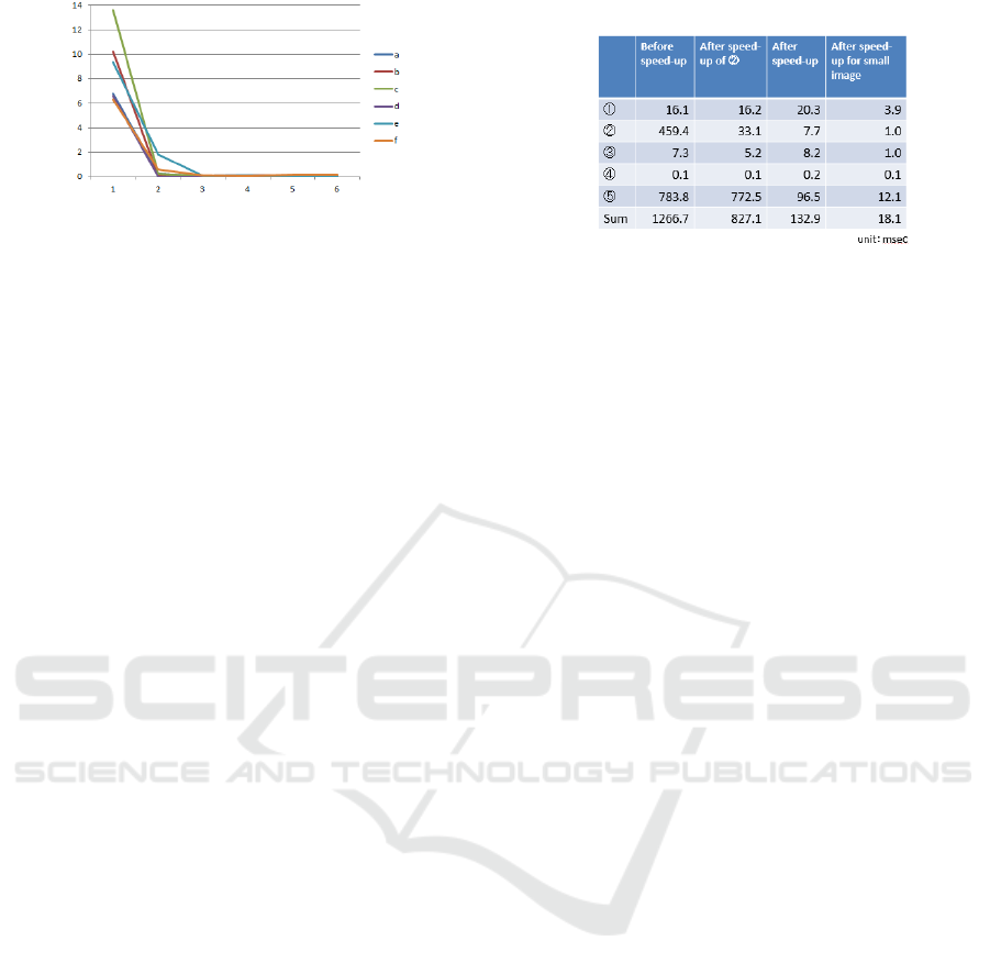
Figure 16: Corrected inclination for each iteration.
omnidirectional cameras are very small and there is
little rigidity between the camera housing and image
plane. Instead, we repeatedly performed the proposed
upright adjustment to demonstrate the precision of
our method. Figure 16 shows the results for the
panoramic images of Figure 12. The number is the
corrected angle for each iteration. Except for Figures
12(e) and (f), the corrected angles after the second
iteration are smaller than 0.3°. This indicates that the
camera inclination estimation accuracy of the
proposed method is 0.3° when enough 3D vertical
lines with adequate length are projected onto the
panoramic images.
5.3 Consideration of Parameters
The parameters of the Hough transform are maxangl,
sampangle, and vertarea. If the inclination of the
camera can reach 30°, the maxangle may be set to
about 2/3 thereof, and sampangle may be set equal to
the estimation accuracy. In the previous processing
example, vertarea = 300, which corresponds to an
elevation angle of about −30° to 30° when the camera
is not tilted. When the image size is changed, vertarea
may be set accordingly. However, if a vertical line is
far from the camera, the floor and ceiling are included,
which is wasteful. It seems that the processing
efficiency could be improved if vertarea were
changed according to the environment and the height
of the camera.
The parameters for line detection are pthresh,
topthresh, and dec, and the parameters for RANSAC
are seednum and thinlier. In the previous example,
pthresh = vertarea/2, topthresh = 10, dec = 10,
seednum = 3, and thinlier = 2 were empirically set,
but good results have been obtained in various indoor
and outdoor environments, and the settings may be
varied accordingly.
5.4 Examination of Processing Speed
Table 1 shows the average time taken to execute parts
① to
⑤ in Figure 10. The first three columns on the
left are the results for 3840×1920 panoramic images
Table 1: Processing speed.
and the rightmost column shows the results for
1280×720 panoramic images. The processor was a
Core i7-8850H and the operating system was
Ubuntu18.04. The first column shows the result
before speedup. In the second column, the processing
speed was increased by tabulating ② and the
processing time was reduced to about 1/15 the
original time. The result in the third column, obtained
after OpenMP acceleration, is a total time of about
133 ms, which can enable real-time processing at
around 5 fps. For the small image, the total time is
about 18 ms, and real-time processing at a camera
frame rate of 15 fps was realized.
6 COMPARISON WITH A
SIMILAR METHOD
In the method of (Kawai 2019) (A) introduced in
Section 2, the edge image of a panoramic image is
created, a block of edge points extending in the
longitudinal direction near the vertical center is
selected, and a straight line is detected by a
conventional Hough transformation. Next,
(
𝜔,𝛼
)
groups are determined, and a sine wave is used to
estimate the inclination of the camera and correct the
image inclination. This approach is the same as the
approach of the proposed method, but the proposed
method (B) has the following advantages.
In A, the longitudinal line is detected by the
Hough transform as described above, but in B, a
theoretical formula for the projection curve of a 3D
straight line is derived. A 3D straight line is detected
by the Hough transform using this formula, so that
edge points far away from the vertical center can also
be used.
In A, the hypothesis that the change in inclination
in the width direction is periodic and can be
approximated by a sine wave is introduced from the
observation of a group of vertical straight lines
detected near the vertical center on the panoramic
image. In B, however, an equation for the inclination
of a group of parallel straight lines on the vertical
Precise Upright Adjustment of Panoramic Images
109

center on the panoramic image is derived. It was
shown analytically that the inclination may be
approximated by a sine wave.
In A, the sine wave is fitted by the least squares
method, whereas in B, robust and accurate fitting is
realized by eliminating outliers using RANSAC.
In A, the estimation accuracy is 3.3° for the first
correction and 1.5° for the second one, but in B, an
estimation accuracy of 0.1° is obtained without the
need for a second step (when the effect of noise can
be eliminated).
For A, it was reported that there were no failure
examples in an experiment of 40 examples, but only
one example was shown. For B, many experiments
were carried out in various environments, and
concrete examples are shown.
7 CONCLUSIONS
In this paper, we proposed a method for upright
adjustment of a panoramic image by detecting the
inclination of the camera from a pre-corrected
panoramic image with high accuracy and at high
speed using a vertical line existing in an indoor
environment or an outdoor environment near a
building.
Because of the nature of this method, it cannot be
used in an environment without vertical lines, but it is
useful in many environments in which autonomous
robots are expected to operate in the future, such as
normal indoor environments, construction sites, and
in and around warehouses. When the lengths of the
projection curves are extremely short, the method is
easily affected by noise, and the upright adjustment
tends to be unstable. However, even in this case, the
value of pthresh can be added as a certainty and the
correct handling can be performed in the post-
processing.
In future, this method will be applied to tasks such
as the self-localization of autonomous robots,
reconstruction of 3D environments, and object
recognition. In addition, by integrating self-
localization estimation and a 3D environment model,
speed-up and robustness will be achieved by learning
the parameters of the upright adjustment depending
on location.
REFERENCES
Bazin, J.-C., Demonceaux, C., et al. 2012. Rotation
estimation and vanishing point extraction by
omnidirectional vision in urban environment. The
International Journal of Robotics Research 31(1): 63-
81.
Bosse, M., Rikoski, R., et al. 2002. Vanishing points and 3d
lines from omnidirectional video. Proceedings.
International Conference on Image Processing, IEEE.
Canny, John 1986. A computational approach to edge
detection. IEEE Transactions on Pattern Analysis and
Machine Intelligence, 8(6): 679-698.
Cipolla, R., Robertson, D., et al. 1999. Photobuilder-3D
models of architectural scenes from uncalibrated
images. Proceedings IEEE International Conference
on Multimedia Computing and Systems, IEEE.
Coughlan, J. M. and Yuille, A. L. 1999. Manhattan world:
Compass direction from a single image by bayesian
inference. Proceedings of the seventh IEEE
international conference on computer vision, IEEE.
Demonceaux, C., Vasseur, P., et al. 2006. Omnidirectional
vision on UAV for attitude computation. Proceedings
2006 IEEE International Conference on Robotics and
Automation, 2006. ICRA 2006., IEEE.
Demonceaux, C., Vasseur, P., et al. 2007. UAV attitude
computation by omnidirectional vision in urban
environment. Proceedings 2007 IEEE International
Conference on Robotics and Automation, IEEE.
Fischler, A., Martin and Bolles, C., Robert 1981. Random
sample consensus: a paradigm for model fitting with
applications to image analysis and automated
cartography. Communications of the ACM, 24(6): 381-
395.
Gallagher, A. C. 2005. Using vanishing points to correct
camera rotation in images. The 2nd Canadian
Conference on Computer and Robot Vision (CRV'05),
IEEE.
Illingworth, John and Kittler, Josef 1988. A survey of the
Hough transform. Computer vision, graphics and
image processing, 44(1): 87-116.
Jayasuriya, M., Ranasinghe, R., et al. 2020. Active
Perception for Outdoor Localisation with an
Omnidirectional Camera. IEEE/RSJ International
Conference on Intelligent Robots and Systems.
Jeon, J., Jung, J., et al. 2018. Deep Upright Adjustment of
360 Panoramas Using Multiple Roll Estimations. Asian
Conference on Computer Vision, Springer.
Joo, K., Oh, T.-H., et al. 2018. Globally optimal inlier set
maximization for Atlanta frame estimation.
Proceedings of the IEEE Conference on Computer
Vision and Pattern Recognition.
Jung, J., Kim, B., et al. 2017. Robust upright adjustment of
360 spherical panoramas. The Visual Computer 33(6-
8): 737-747.
Jung, R., Lee, A. S. J., et al. 2019. Deep360Up: A Deep
Learning-Based Approach for Automatic VR Image
Upright Adjustment. 2019 IEEE Conference on Virtual
Reality and 3D User Interfaces (VR), IEEE.
Kawai, N. 2019. A method for rectifying inclination of
panoramic images. ACM SIGGRAPH 2019 Posters,
ACM.
Lee, H., Shechtman, E., et al. 2013. Automatic upright
adjustment of photographs with robust camera
VISAPP 2021 - 16th International Conference on Computer Vision Theory and Applications
110

calibration. IEEE Transactions on Pattern Analysis and
Machine Intelligence 36(5): 833-844.
Liu, M., Pradalier, C., et al. 2013. Visual homing from scale
with an uncalibrated omnidirectional camera. IEEE
transactions on robotics 29(6): 1353-1365.
Milford, M. and Wyeth, G. 2010. Persistent navigation and
mapping using a biologically inspired SLAM system.
The International Journal of Robotics Research 29(9):
1131-1153.
Natraj, A., Ly, D. S., et al. 2013. Omnidirectional vision for
UAV: Applications to attitude, motion and altitude
estimation for day and night conditions. Journal of
Intelligent & Robotic Systems 69(1-4): 459-473.
Payá, L., Gil, A., et al. 2017. A state-of-the-art review on
mapping and localization of mobile robots using
omnidirectional vision sensors. Journal of Sensors
2017.
Ricoh. 2020. "Theta." from https://theta360.com/en/.
Schindler, G. and Dellaert, F. 2004. Atlanta world: An
expectation maximization framework for simultaneous
low-level edge grouping and camera calibration in
complex man-made environments. Proceedings of the
2004 IEEE Computer Society Conference on Computer
Vision and Pattern Recognition, 2004. CVPR 2004.,
IEEE.
Wang, C., Tanahashi, H., et al. 2003. Slant estimation for
active vision using edge directions in omnidirectional
images. Proceedings 2003 International Conference on
Image Processing (Cat. No. 03CH37429), IEEE.
Xiao, J., Ehinger, K. A., et al. 2012. Recognizing scene
viewpoint using panoramic place representation. 2012
IEEE Conference on Computer Vision and Pattern
Recognition, IEEE.
Yagi, Y. 1999. Omnidirectional sensing and its applications.
IEICE transactions on information and systems 82(3):
568-579.
Zhang, L., Lu, H., et al. 2016. Vanishing point estimation
and line classification in a Manhattan world with a
unifying camera model. International Journal of
Computer Vision 117(2): 111-130.
Precise Upright Adjustment of Panoramic Images
111
