
MoCaCo: A Simulator Framework for Motion Capture Comparison
Florian Herrmann, Steffen Kr
¨
uger and Philipp Lensing
Osnabr
¨
uck University AS, Albrechtstraße 30, Osnabr
¨
uck, Germany
Keywords:
Motion Capture, Inverse Kinematics, Virtual Reality.
Abstract:
With human motion capture being used in various research fields and the entertainment industry, suitable sys-
tems need to be selected based on individual use cases. In this paper we propose a novel software framework
that is capable to simulate, compare, and evaluate any motion capturing system in a purely virtual way. Given
an avatar as input character, a user can create an individual tracking setup by simply placing trackers on the
avatars skin. The physical behavior of the placed trackers is configurable and extendable to simulate any ex-
isting tracking device. Thus it is possible e.g. to add or modify drift, noise, latency, frequency, or any other
parameter of the virtual trackers. Additionally it is possible to integrate an individual inverse kinematics (IK)
solving system which is steered by the placed trackers. This allows to compare not only different tracker
setups, but also different IK solving systems. Finally users can plug-in custom error metrics for comparison of
the calculated body poses against ground truth poses. To demonstrate the capabilities of our proposed frame-
work, we present a proof of concept by implementing a simplified simulation model of the HTC vive tracking
system to control the VRIK solver from the FinalIK plugin and calculate error metrics for positional, angular,
and anatomic differences.
1 INTRODUCTION
In today’s world motion capture has become a com-
mon technique in various fields of research, includ-
ing biomechanics (Fern
´
andez et al., 2012), virtual-
and augmented reality (Chan et al., 2011; Vera et al.,
2011), and rehabilitation (Metcalf et al., 2013). As
these fields have different requirements for captur-
ing motion data, finding a system fulfilling them can
be difficult. Commercially available systems come
in a great variety, ranging from expensive marker-
based optical ones developed by Vicon to inexpensive
vision-based approaches like the Microsoft Kinect.
As these use different techniques to capture the mo-
tion, factors such as accuracy, occlusion problems,
and sampling rate differ. Because of these reasons,
papers analyzing systems for specific use cases arose
(Van der Kruk and Reijne, 2018; Niehorster et al.,
2017).
This paper is motivated by the idea that the
comparison of motion capture systems given a spe-
cific task should be made easier and more general-
ized. Therefore, we propose a framework which en-
ables simple virtual integration of motion capture sys-
tems for simulation and evaluation. To achieve this,
our system offers multiple interfaces for implement-
ing custom components at specific simulation steps.
Those steps cover modeling of tracking hardware,
solving poses through inverse kinematics (IK) and
comparing occurring deviations by an error analysis
component.
To show how the designed process can be used,
we include two proof of concept tests evaluating pos-
sible use cases where the configuration of a virtual
motion capture system could be verified before pur-
chasing the hardware. By using our frameworks in-
terfaces we implement different known systems. We
utilize a simplified tracker simulation model for HTC
Vive trackers and a port of the VRIK solver from the
FinalIK plugin from the Unity 3D Engine for pose
reconstruction. Additionally we realized error analy-
sis components calculating positional, rotational, and
anatomic angle differences. All test results are avail-
able on our website
1
. Summarized our contributions
are:
1. A framework using a novel process for modeling
motion capture systems in a virtual way, by in-
corporating customizable components for tracker
behavior and pose estimation.
2. A novel algorithm to dynamically calculate
1
https://github.com/MoCaCoSimulator/
MoCaCoSimulator/ releases/tag/HTC VRIK
Herrmann, F., Krüger, S. and Lensing, P.
MoCaCo: A Simulator Framework for Motion Capture Comparison.
DOI: 10.5220/0010239101930200
In Proceedings of the 16th International Joint Conference on Computer Vision, Imaging and Computer Graphics Theory and Applications (VISIGRAPP 2021) - Volume 1: GRAPP, pages
193-200
ISBN: 978-989-758-488-6
Copyright
c
2021 by SCITEPRESS – Science and Technology Publications, Lda. All rights reserved
193
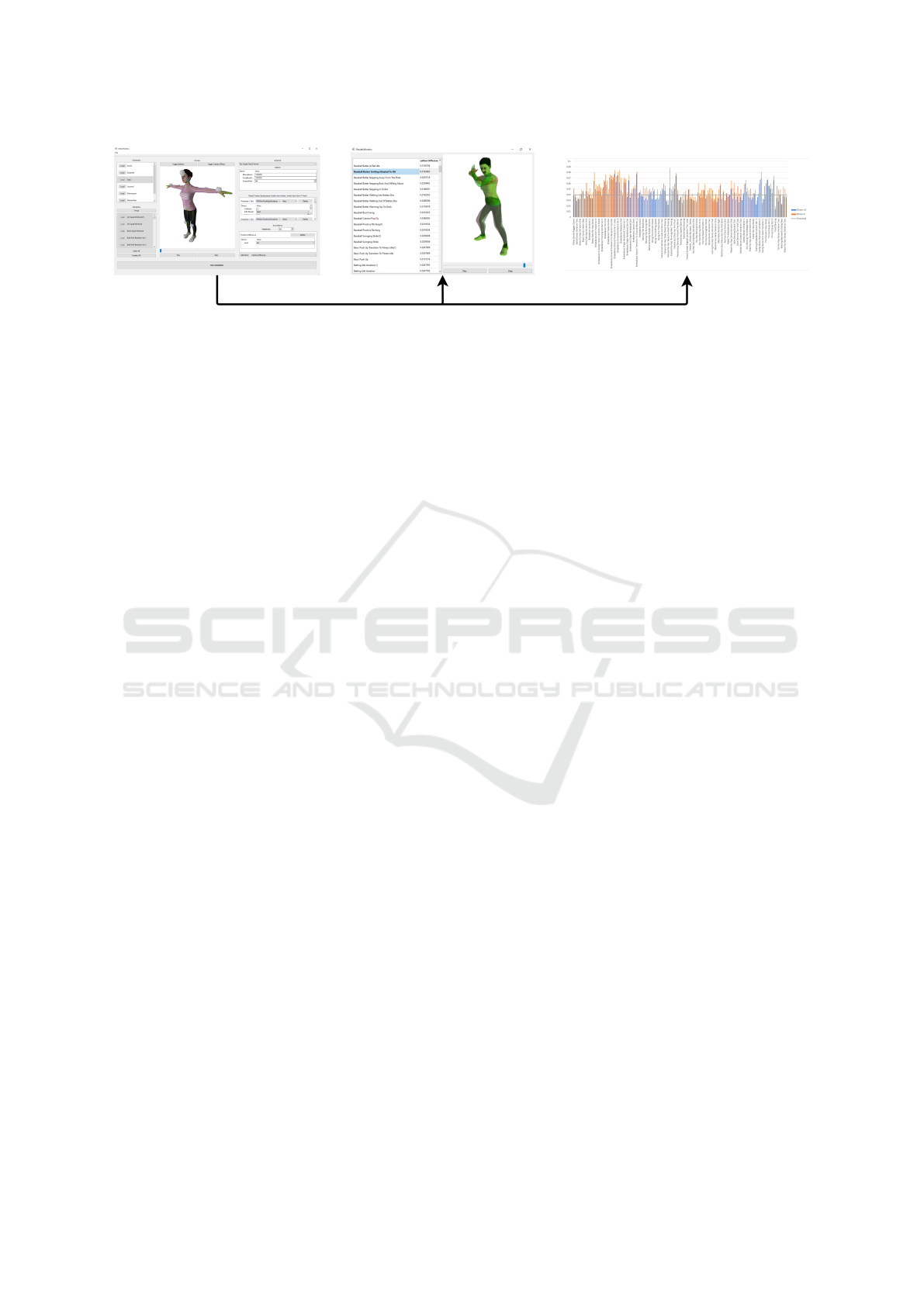
Figure 1: Process of evaluating a virtual motion capture system. By recreating an existing system, shown in the left image,
our framework is able to process multiple animations to provide possibilities for visual evaluation, shown in the central image,
or in-depth data analysis by third party software, shown in the right image.
anatomic angles of a humanoid, by minimizing
required movement.
3. An evaluation of the proposed framework by two
proof of concept tests, using a simplified simu-
lation model for HTC Vive trackers, and recon-
structing a characters pose with the VRIK solver.
After presenting related works in section 2, our
paper is separated into two main parts: The first one
explains the process of our framework, as shown in
figure 1, in detail. Section 3 covers the general struc-
ture of the software, while programmable components
are explained in section 4. The second part, covered
in section 5, presents two proof of concept tests to
evaluate our framework. Each of the tests is first ex-
plained in detail and afterwards the results are pre-
sented. Lastly we conclude our work in section 6.
2 RELATED WORKS
For the comparison of motion capture data different
methods to calculate error metrics have been pro-
posed. These can be separated into tracking and pose
based approaches, depending on the data used in the
calculation.
The error of a tracking system can be described as
a metric representing the difference between tracked
and ground truth data. Because these errors give in-
sights into the quality of a given capture system, pa-
pers can be found for almost all available approaches
today. While the technical specifications of motion
capture systems can theoretically be used to compare
them, most scientific tests are done in real environ-
ments. Therefore, these results reflect the real world
abilities for each system. In (Merriaux et al., 2017)
the authors tested the positional performance of the
Vicon system. The accuracy and precision of a HTC
Vive was evaluated in (Borges et al., 2018) with re-
spects to static and dynamic scenarios. A similar
test by (Niehorster et al., 2017) focused on the sys-
tem capabilities in scientific research. Furthermore,
deviations for the joint positions, from the first and
second generation of Microsoft’s Kinect system, to
captured ground truth data were calculated in (Wang
et al., 2015).
Pose based error metrics deal with the calculation
of visual differences between two poses. In (Wang
and Bodenheimer, 2003) the authors used a metric,
incorporating joint velocities and rotations, to find
transitional points between two different animations.
For a tai chi training program presented in (Jin et al.,
2012), a metric utilized weighted rotations for joints,
with different degrees of freedoms (DoF). Another
approach proposed in (Kovar et al., 2002) calculates
differences between two poses solely based on the vi-
sual representation of characters. To achieve this, the
authors exploited vertices of the models to represent
poses as a point cloud which is adopted in the calcu-
lation afterward.
The HuManS toolbox (Wieber et al., 2006) in-
cludes models for converting optical tracking data
from Vicon and Optotrak motion capture systems to a
humanoid representation. An interface to implement
custom converters is also included. After the data has
been transformed, the toolbox can calculate various
values concerning the kinetics and dynamics of the
model.
For systems tracking only a subset of human
joints, inverse kinematics can be utilized to calculate
the missing data. These can be separated into cat-
egories based on the approach they use and a com-
prehensive survey of relevant techniques used in the
field of animation can be found in (Aristidou et al.,
2018). Different IK approaches include, but are not
limited to: Jacobian based (Buss, 2004), data-driven
approaches (Grochow et al., 2004; Wei and Chai,
2011; Wu et al., 2011) and heuristic, iterative so-
lutions(Aristidou et al., 2016; Unzueta et al., 2008;
RootMotion, 2017).
GRAPP 2021 - 16th International Conference on Computer Graphics Theory and Applications
194
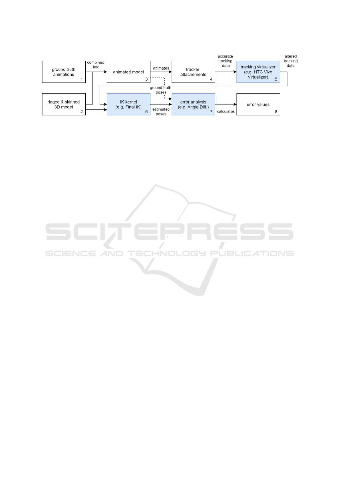
Figure 2: Data flow of the simulation process. The blue highlighted components offer interfaces for developing custom
implementations.
3 COMPONENTS AND
STRUCTURE OF THE
FRAMEWORK
Figure 2 captures the overall structure of our simula-
tion process. Multiple animations (1) are combined
with a character model (2). The resulting animated
model (3) moves trackers which are attached to its
surface (4). The tracking virtualizer component (5)
aims to alter the trackers movement, by simulating
realistic tracking behavior of an existing motion cap-
ture system. With the resulting altered trajectories
and a character model, the IK kernel component (6)
is able to solve the characters kinematic structure. Er-
ror analysis components (7) compare the simulated,
against the ground truth animation. Error values (8)
are the result of this process and can be used to com-
pare different systems. This section covers the struc-
ture in detail.
To obtain meaningful evaluation results of a hard-
ware system, multiple animations are processed by a
single configuration. All character and animation files
have to be stored within specific folders to be read by
the framework. They are then loaded automatically,
when required. When starting the simulation the ani-
mations are combined successively with the character
model. Tracker attachments are placed on the charac-
ters surface. By animating the character those attach-
ments are being moved as well. Their movement re-
flects the accurate trajectory of the attachment. Since
existing motion capture systems do not record flaw-
less tracking data, this trajectory has to be altered real-
istically. The tracking virtualizer component of each
tracker can access the corresponding movement data
to generate a new animation reflecting the estimated
behavior of the physical tracker. Our framework al-
lows the combination of different tracking hardware
in a single setup, since each tracker is processed by an
individually assignable virtualizer. The altered track-
ing data for each tracker is passed to the IK kernel
component, utilizing them in an IK algorithm to solve
character poses over the animation time. Solved poses
are saved into another generated animation which is
the estimated motion capture result of the tested sys-
tem. To compare the solved with the ground truth
animation, both are passed to the error analysis step.
Each selected component calculates its results by re-
ceiving every pose of the character from both anima-
tions over the animation time. Afterwards differences
between both poses are saved in a floating-point num-
ber array. Each of those values represents a devia-
tion from the ground truth data. After running multi-
ple simulations with different configurations, this data
can be utilized for comparison. The tracking virtual-
izer, IK kernel, and error analysis components are the
core parts of our framework and are further explained
in section 4.
4 CONFIGURABLE
COMPONENTS
The three highlighted components of the simulation
process in figure 2 form the core of the proposed
framework. The tracking virtualizer and IK kernel
component enable the integration of most motion cap-
ture systems into our system. Integrations of the er-
ror analysis component are able to evaluate the differ-
ences between ground truth and simulated data. Each
component functions independently and contains an
interface with a defined in- and output structure for
standardized interaction within the system. Any inte-
grated component offers the optional specification of
adjustable parameters which can be altered during run
time. These parameters are intended to represent vari-
able settings for testing purposes, e.g. sample rate.
These parameters are automatically displayed in the
UI of this system. Detailed functionality of each com-
ponent will be explained in the following subsections.
MoCaCo: A Simulator Framework for Motion Capture Comparison
195

4.1 Tracking Virtualizers
The purpose of our tracking virtualizer component
(see figure 2) is the generation of realistic trajecto-
ries from ground truth data. Each placed tracker has
a particular integration of the tracking virtualizer ap-
plied. Therefore, the virtualizer of each tracker can be
parameterized separately. To achieve a realistic tra-
jectory, the integration has to take care of alteration
to the position and rotation data by the anticipated be-
havior of an existing tracking system. The alterations
can range from adding simple noise values, reflecting
general flaws inherit in every system, to full simula-
tions, if the entire functionality of a system is known.
The component has access to the position and ori-
entation data of the corresponding tracker during the
simulated ground truth animation. The altered data
is saved into a basic animation which represents the
simulated trajectory. The total duration of the ground
truth and simulated animation has to match for later
comparison by the error metrics component. When
every tracker instance completed the simulation pro-
cess the resulting altered tracker trajectories are com-
bined into a single newly generated animation. This
animation is passed to the IK solver component for
further processing.
4.2 Inverse Kinematic Solvers
The IK solver component’s (see figure 2) purpose is
the generation of a humanoid animation, solely based
on the simulated data from the tracking virtualizers.
As input the component receives every generated tra-
jectory and the character model. An IK solver con-
tains slots for the tracking virtualizers corresponding
to targets required for calculation of a humanoid pose.
Since the trajectories contain data about the move-
ment of a tracking device on the skin of a character
model, the solver has to compute the corresponding
joint movement.
Our framework offers the possibility to define
the required targets for an IK solver implementation
which are then assignable to a tracking virtualizer by
utilizing the UI. Positional and rotational offset infor-
mation between a tracker and a corresponding joint,
can be calculated while the character model is set to
the default pose (usually T-pose). This information is
then available to the IK solver in the simulation pro-
cess and can be combined with the tracking virtualizer
data to obtain an estimation of the real joint pose.
4.3 Error Analysis Component
The error analysis component (see figure 2) is tasked
with the calculation of differences between two poses
of the same character. These are extracted from the
ground truth and resulting animation from the simu-
lation. Poses are passed to all selected error analysis
components at each sample step of a simulation. Ev-
ery component calculates a floating-point number, de-
scribing the amount of difference between the poses.
The results from every used component are saved for
the corresponding sample. By forcing the component
to compare poses instead of complete animations, the
system ensures a single result value for each compo-
nent and timestamp.
We include two basic and one novel error analy-
sis components with our framework. The basic ones
calculates positional and rotational differences be-
tween joints. Our novel analysis component calcu-
lates anatomic angle differences in a different way
than the proposes from the International Society of
Biomechanics (ISB) (International Society of Biome-
chanics, 2020). Our idea behind the proposed calcula-
tion is the minimization of required motion, excluding
the twist, for reasons explained shortly. The neutral
pose with arms down is used as our starting configu-
ration. For hinge joints having only one DoF, namely
elbows and knees, the method simply calculates the
rotation around their anatomical rotational axis. Ball
and socket joints, including shoulders and hips, have
two DoF after the exclusion of the twist. Therefore,
our algorithm calculates the angles for both possible
rotation orders and then chooses the order requiring
less movement. The twist of a joint, if applicable, is
always calculated as the last part of the rotation order.
This approach was chosen, because physiotherapists
analyze the current pose in terms of positional influ-
ence from anatomic angles on the next joint. As the
twist can not change the position of the next joint in a
chain, we decided to always calculate it at last.
5 PROOF OF CONCEPT TESTS
In order to evaluate our framework we created two
proof of concept test scenarios. Each of them is mo-
tivated by a question our potential users could have
in their studies. Starting off from just these, we de-
signed our cases to demonstrate, how our framework
can help by simulating an arbitrary motion capture
system. We chose to create two scenarios, present-
ing different conceptual ideas. In the following we
present a summarized version of each of them:
GRAPP 2021 - 16th International Conference on Computer Graphics Theory and Applications
196

1. Can I reduce the tracker set for a specific
animation set without significant quality de-
crease?
Evaluation of a reference and reduced tracker con-
figuration in terms of positional performance.
2. How can I check if more trackers need to be in-
corporated to stay under a given error thresh-
old?
Simulation of possible tracking setups and check-
ing which configuration is capable of the require-
ments.
This section starts with a general description of
our implemented virtual motion capture system, de-
tailing the setup for all test cases. Afterwards we
present our two proof of concept cases in their own
separate subsections, explaining what data was used,
which difference metrics we calculated, and an anal-
ysis of the results. Lastly we close this section with a
discussion summarizing our results and insights from
running these tests.
5.1 General System Configuration
We implemented a simplified simulation of HTC Vive
trackers as virtual tracking device for our tests. The
impementation depends on the python based IMUSim
(Young et al., 2011). As the Vive trackers use a hybrid
approach, two different sample rates are required to
control each system. Unfortunately there is no infor-
mation published on either the Lighthouse or IMU up-
date rate. We therefore assume rates measured from
tests done in (Kreylos, 2016). For the Lighthouse sys-
tem with two emitters the author achieved an update
frequency of 120Hz, while values for IMUs where
different based on the device measured, i.e. 1006Hz
for the headset and 366Hz for the hand controllers.
We chose to utilize the lower frequency, meaning our
trackers mimic Vive controllers. Our IMU simulation
is done with an uncalibrated Ideal IMU model and the
basic gyro integrator from IMUSim.
The VRIK implementation of the FinalIK pack-
age for the Unity game engine was ported to our soft-
ware as an IK solver example. We chose FinalIK,
since it is fast, i.e. suitable to run multiple simula-
tions in quick succession, and widely utilized as so-
lution for various video game software (Lang, 2020).
Specifically we used the VRIK solver which aims to
be a fast, full body solver for virtual reality systems.
For each test some of the default settings from VRIK
have to be adjusted. Since VRIK is designed to be
used in virtual reality applications, the default track-
ing setup consists of head- and hand-trackers. While
these targets can be easily supplied by common con-
sumer grade VR systems, e.g. HTC Vive or Oculus
Rift, we require more control over the avatar. There-
fore we incorporate more targets, with specific config-
urations described in each testing scenario. To control
the whole avatar for a VR setup, an algorithm for lo-
comotion is activated by default, as well as the option
to plant the feet on the floor to prevent clipping ar-
tifacts. Because all our test cases imply a dedicated
target for each foot, we disabled the locomotion and
feet grounding function. For the spine part of VRIK
the default minimum head height is set to 0.8 meters.
Because we intend to use various animations going
below this threshold, e.g. Hip Hop dance motions, we
set this value to 0.0 meters. This basically ensures
that the head is not able to move below ground level.
Because the trackers are placed on the avatars skin
but VRIK requires targets to be at the joint position
and rotation we utilize the tracker-to-joint-offset as
mentioned in section 4.2. Knees and elbows are an
exception in the VRIK system, since these trackers
only define the bending direction. Therefore only the
rotation offset has to be applied to the tracker data.
Without knee or elbow trackers the bending directions
are calculated by VRIK based on the relationship be-
tween joints in the extremities. Unfortunately this
approach does not work with entirely straight limbs
which is the case for our selected characters. Since
altering the VRIK implementation is no option, be-
cause the results would not reflect the behavior of the
original system anymore, we chose to rotate the knees
back by 5 degrees before the simulations, but did not
change the elbow rotation, because we did not witness
problematic solved results for them.
At last we adjusted the general calculation sam-
ple rate for the inverse kinematics kernel and error
analysis component to match the highest frequency in
our tracking virtualizer system. Thereby the impact of
every simulated tracker keyframe is incorporated into
the results. Our highest sample rate in the Vive track-
ing virtualizer is the IMU update at 366hz, therefore
this value is used for calculation updates.
5.2 Reduced Tracker Setup Evaluation
for Walking Animations
The first test is a comparison between two different
tracking setups for our implemented virtual motion
capture system. We want to evaluate whether a re-
duced tracker setup can provide similar accuracy for
a carefully selected set of animations. For our test we
chose walking motions, because these normally share
characteristics which can be exploited in the reduc-
tion process. An idealized walk animation consists of
a close to upright spine posture, a head and hip mo-
tion effecting the height value in a sine wave like man-
MoCaCo: A Simulator Framework for Motion Capture Comparison
197

Figure 3: Position difference between ground truth and sim-
ulated results for walking animations with and without a hip
target.
ner, and only minor spread sideways for all limbs. By
analyzing these properties, we chose to test walking
motions with and without utilizing the hip target from
VRIK. We suspect that the solved animation is close
to the ground truth data, because the hip pose depends
on the head and legs for gait animations which are in-
cluded as separated targets in our test. Therefore we
specially want to evaluate, if VRIK is capable of in-
corporating these dependencies into acceptable pose
estimation.
For the first simulation, trackers for the hands,
toes, and head are placed on the characters surface.
When a configuration lacks a target for the hips joint,
VRIK provides options for maintaining the so called
body stiffness in position and rotation. Both of these
were set to 0.5 after some empirical testing. The
tested animations were downloaded from Mixamo by
filtering for the keyword ”walk”. Because the down-
loaded files included some non walking animations,
we removed all files locally whose names did not con-
tain the word ”walk”.
The results from figure 3 disprove our assumption
for walk analysis with VRIK. While we did suspect
the results to be slightly worse, the simulated anima-
tions for both male and female avatars show signifi-
cant improvements by incorporating a hip tracker. Ex-
plicitly the combined difference went from 15.29cm
to 0.69cm for the hip and from 7.11cm to 2.7cm for
the average position. We chose to further analyze the
simulated animations by examining visual differences
in the comparison window shown the center image of
Figure 1. This led us to the discovery of an inherit
flaw in VRIK. The solver resets the avatar rig to the
initial pose before each update. While we assumed
that the hip joint without a separate tracker would be
calculated through the dependencies on other targets,
i.e. hands, head, and toes, we discovered that the joint
is merely pulled into the direction of them. Conse-
quently the hip drags back to the initial position in the
simulated animations. In summary we do not recom-
mend the VRIK solver for gait animations without the
inclusion of a hip tracker.
Figure 4: Position difference between ground truth and sim-
ulated results for dance animations with and without elbow
goals.
5.3 Bending Goals Evaluation for
Dancing Animations
For the second use case we want to test our simulated
tracking data against a given threshold. We chose to
evaluate, if VRIKs bend goals are necessary for the
capture of dance animations. Since dances exhibit
complex motions for arms, we are interested in dances
that can be performed without separate trackers for
elbows. Therefore we specified 4cm in the elbows
position offset to serve as a baseline for a acceptable
capture quality. For the simulation, we chose to use
the neutral mannequin character model from Mixamo.
The database provides 140 different dancing anima-
tions, of which three were not included in the simu-
lation, because they just contained a single pose and
the use case requires animations. We sorted them into
12 different categories based on the style. Another
category is created for dances not assignable to any
of them. For this test we setup two different tracker
configurations. For the full tracking setup we incor-
porated trackers for the following targets of VRIK:
• Spine targets: hip, head
• Arm targets : left/right hands, left/right elbows
bend goal
• Leg targets : left/right toes, left/right knees bend
goal
This setup includes every target of VRIK apart
from the chest, because we observed better accuracy
results empirically without it. The second setup is
also based on this setup, but does not include bend
goal targets for the knees and elbows. Since this test
solely focuses on positional deviation for our thresh-
old, only this offset is calculated for the elbow joints.
The results for elbow offsets presented in figure
4 reveals an improvement for every dancing style
when incorporating a bend goal. Based on our cho-
sen threshold for positional errors, the number of ac-
ceptable elbow motions increases from only one to
GRAPP 2021 - 16th International Conference on Computer Graphics Theory and Applications
198

eight categories which is over half of all possible
styles. Another insight from our test is the identifi-
cation which styles can be captured with either both
tracker setups or none of them. The only dance stay-
ing under our threshold even without bend goals was
ballet which after further inspection of the anima-
tions is caused by long periods having stretched arms,
i.e. the bend goals have no impact on the elbows.
In contrast five categories did not match our thresh-
old with either tracker configuration, namely Break-
dance, Jazz, Swing, the Thriller Dance and Belly
Dancing. Firstly these styles have heavy emphasis
on arm movement which explains the high differences
between the tracker setups. For the full configuration
we were astonished, because House had higher off-
sets than Jazz without bend goals, but still met our
threshold by the incorporation of them. A visual ex-
amination showed expressive arm motions in both of
them, but the direction of movement was quite differ-
ent, Jazz has a lot of movement over the head, while
House dances push arms mostly in front of the chest.
We suspect these differences appeared, because we
employed the same tracker placement on the char-
acters skin for both dance styles. Since the skin is
moved based on the animations, one general tracker
placement could perhaps not work for every motion
type. This theory is supported by a small test using the
same animation with minor tracker placement varia-
tions which resulted in different offsets. Therefore we
conclude that each style could possibly be configured
with a tracker setup to fit our given threshold by test-
ing different tracker placements.
5.4 Discussion of the Tests and Results
Our proof of concept tests presented some interesting
insights into our implemented virtual motion capture
system. For our first test we assumed the removal
of the hip tracker for the simulation of walking an-
imations, would not affect the overall capture qual-
ity in a significant way. Since the results exhibited
heavy deviations, we found a flaw inside the VRIK
system where the hip is just dragged in the direc-
tion of the characters other joints if no hip target is
present. Therefore we concluded, the VRIK should
not be used without tracking this specific target. In
our second case we evaluated whether the elbow bend
goal is necessary for capturing of different dancing
styles given a threshold value for positional offset.
Our results showed that bend goals decreased the po-
sitional error overall and made over half of the styles
capturable keeping our threshold. In this test we also
presented insights into how proper tracker placement
affects two styles that were similar in expressiveness
of arm motion, but did not display the same error val-
ues. To download all results from the complete test
suite, please visit the results website
2
. Finally, these
insights were obtained from just two simple test cases.
Therefore we are confident the framework can help
other researchers in evaluating their own systems with
their individual test cases.
6 CONCLUSION
A framework has been proposed which is capable
to simulate, compare and evaluate any existing mo-
tion capture system in a time and cost efficient way.
Thanks to the open software design, the framework
can be easily extended by more tracking systems and
IK solving algorithms. This was ensured by integrat-
ing interfaces at crucial system components which al-
low for fast replacements of functionality without re-
considering the entire motion pipeline.
The system has been tested by implementing
an approach for all available software components
within the system. We chose to simulate the HTC
Vive trackers and solve for missing joint values with
the VRIK IK solver from FinalIK. We provided er-
ror analysis components for positional, angular and
anatomic differences between the real and simulated
data. The test results confirm, the framework is ca-
pable to efficiently compare different tracking setups
in a comprehensible way which leads to an objective
method for determining the quality of a given tracking
and IK solving approach against ground truth data.
For future work we plan to improve our frame-
work by adding interfaces for systems based on video
analysis. While these techniques could still be incor-
porated into the proposed tracking emulation system,
by using the supplied inputs, a specialized interface
enabling native support in the framework would help
developers implementing these types of systems. We
additionally plan to increase the amount of integrated
motion capture systems, with the goal of having a
default implementation for each motion capture tech-
nique.
We publish the entire source code
3
of the frame-
work under the GPL license to invite other researchers
and system engineers to utilize or extend it to their
needs. We are convinced that a broad application
of the framework and a vivid developer community
could lead to a greater comparability between differ-
2
https://github.com/MoCaCoSimulator/
MoCaCoSimulator/ releases/tag/HTC VRIK
3
https://github.com/MoCaCoSimulator/
MoCaCoSimulator
MoCaCo: A Simulator Framework for Motion Capture Comparison
199

ent motion capture approaches and thus, to more ob-
jective evaluations.
REFERENCES
Aristidou, A., Chrysanthou, Y., and Lasenby, J. (2016). Ex-
tending fabrik with model constraints. Computer An-
imation and Virtual Worlds, 27:35–57.
Aristidou, A., Lasenby, J., Chrysanthou, Y., and Shamir,
A. (2018). Inverse kinematics techniques in com-
puter graphics: A survey. Computer Graphics Forum,
37:35–58.
Borges, M., Symington, A., Coltin, B., Smith, T., and Ven-
tura, R. (2018). Htc vive: Analysis and accuracy im-
provement. pages 2610–2615.
Buss, S. (2004). Introduction to inverse kinematics with
jacobian transpose, pseudoinverse and damped least
squares methods. IEEE Transactions in Robotics and
Automation, 17.
Chan, J. C. P., Leung, H., Tang, J. K. T., and Komura, T.
(2011). A virtual reality dance training system us-
ing motion capture technology. IEEE Transactions on
Learning Technologies, 4(2):187–195.
Fern
´
andez, A., Susin, T., and Lligadas, X. (2012). Biome-
chanical validation of upper-body and lower-body
joint movements of kinect motion capture data for re-
habilitation treatments. pages 656–661.
Grochow, K., Martin, S., Hertzmann, A., and Popovic, Z.
(2004). Style-based inverse kinematics. ACM Trans.
Graph., 23:522–531.
International Society of Biomechanics (2020). Stan-
dards - international society of biomechanics.
https://isbweb.org/activities/standards. Last accessed
June 18, 2020.
Jin, Y., Hu, X., and Wu, G. (2012). A tai chi training
system based on fast skeleton matching algorithm.
In Fusiello, A., Murino, V., and Cucchiara, R., edi-
tors, Computer Vision – ECCV 2012. Workshops and
Demonstrations, pages 667–670, Berlin, Heidelberg.
Springer Berlin Heidelberg.
Kovar, L., Gleicher, M., and Pighin, F. (2002). Motion
graphs. ACM Trans. Graph., 21(3):473–482.
Kreylos, O. (2016). Lighthouse tracking examined.
http://doc-ok.org/?p=1478. Last accessed June 18,
2020.
Lang, P. (2020). Games powered by final ik.
https://rootmotion.freshdesk.com/support/
solutions/articles/77000058439-games-powered-
by-final-ik. Last accessed June 17, 2020.
Merriaux, P., Dupuis, Y., Boutteau, R., Vasseur, P., and Sa-
vatier, X. (2017). A study of vicon system positioning
performance. Sensors, 17:1591.
Metcalf, C. D., Robinson, R., Malpass, A. J., Bogle, T. P.,
Dell, T. A., Harris, C., and Demain, S. H. (2013).
Markerless motion capture and measurement of hand
kinematics: Validation and application to home-based
upper limb rehabilitation. IEEE Transactions on
Biomedical Engineering, 60(8):2184–2192.
Niehorster, D. C., Li, L., and Lappe, M. (2017). The accu-
racy and precision of position and orientation tracking
in the htc vive virtual reality system for scientific re-
search. i-Perception, 8.
RootMotion (2017). Final ik - rootmotion. http://www.root-
motion.com/final-ik.html. Last accessed June 16,
2020.
Unzueta, L., Peinado, M., Boulic, R., and Suescun,
A. (2008). Full-body performance animation with
sequential inverse kinematics. Graphical Models,
70:87–104.
Van der Kruk, E. and Reijne, M. (2018). Accuracy of human
motion capture systems for sport applications; state-
of-the-art review. European Journal of Sport Science,
18:1–14.
Vera, L., Gimeno, J., Coma, I., and Fern
´
andez, M. (2011).
Augmented mirror: Interactive augmented reality sys-
tem based on kinect. In Campos, P., Graham, N.,
Jorge, J., Nunes, N., Palanque, P., and Winckler, M.,
editors, Human-Computer Interaction – INTERACT
2011, pages 483–486, Berlin, Heidelberg. Springer
Berlin Heidelberg.
Wang, J. and Bodenheimer, B. (2003). An evaluation of
a cost metric for selecting transitions between mo-
tion segments. Proceedings of the 2003 ACM SIG-
GRAPH/Eurographics Symposium on Computer Ani-
mation.
Wang, Q., Kurillo, G., Ofli, F., and Bajcsy, R. (2015). Eval-
uation of pose tracking accuracy in the first and second
generations of microsoft kinect.
Wei, X. and Chai, J. (2011). Intuitive interactive human-
character posing with millions of example poses.
Computer Graphics and Applications, IEEE, 31:78 –
88.
Wieber, P.-B., Billet, F., Boissieux, L., and Pissard-Gibollet,
R. (2006). The humans toolbox, a homogenous frame-
work for motion capture, analysis and simulation.
Wu, X., Tournier, M., and Reveret, L. (2011). Natural char-
acter posing from a large motion database. IEEE Com-
puter Graphics and Applications, 31(3):69–77.
Young, A., Ling, M., and Arvind, D. (2011). Imusim: A
simulation environment for inertial sensing algorithm
design and evaluation. pages 199–210.
GRAPP 2021 - 16th International Conference on Computer Graphics Theory and Applications
200
