
Improving Digital Twin Experience Reports
Bentley James Oakes, Ali Parsai, Simon Van Mierlo, Serge Demeyer, Joachim Denil,
Paul De Meulenaere and Hans Vangheluwe
University of Antwerp, Flanders Make Vzw, Belgium
bentley.oakes, ali.parsai, simon.vanmierlo, serge.demeyer, joachim.denil, paul.demeulenaere,
Keywords:
Digital Twins, Digital Twinning, Digital Twin Classification, Modelling and Simulation.
Abstract:
Digital twins (DTs) are prevalent throughout industrial domains as evidenced by the rapid pace of experience
reports in the literature. However, there remains disagreement about the precise definition of a DT and the
essential characteristics in the DT paradigm, such as the scope of the system-under-study and the time-scale of
its communication with the DT. These experience reports could therefore be hampering further classification
and research insights by not reporting all of these relevant details about the DT solutions. We address these
concerns by providing a conceptual structure for DTs as a common understanding and checklist for researchers
and practitioners to precisely describe the characteristics and capabilities of their DT solutions. We express five
experience reports using our structure to demonstrate its applicability and role as a guideline to improve the
reporting of characteristics and increase the clarity of future experience reports.
1 INTRODUCTION
The digital twinning concept has seen a recent explo-
sion of interest in industry as system designers, manu-
facturers, and users explore the possibilities of having
a digital version of their system-under-study (SUS)
available for simulation. This is seen in multiple do-
mains at multiple levels of detail, from digital versions
of factory machines (Min et al., 2019) to energy man-
agement for a district in Helsinki (Ruohom
¨
aki et al.,
2018).
Grieves et al. introduced the term ‘digital twin’
(DT) in 2002 in the context of product life-cycle man-
agement (Grieves and Vickers, 2017). A DT was either
the digital version of the pre-manufactured product
through the design cycle, or a digital version of the
product in use that evolves to capture relevant detail
and behaviour. This definition has expanded to be ap-
plied to further domains, such as “a DT is a virtual
instance of a physical system (twin) that is continually
updated with the latter’s performance, maintenance,
and health status data throughout the physical system’s
life-cycle” (Madni et al., 2019).
The promise of DTs is their ability to reason about
the system’s behaviour in the past, present, and future
under different conditions, enabling advanced system
error detection and prediction, visualization, optimiza-
tion, or other activities (Rasheed et al., 2020). For
example, maintenance could be automatically sched-
uled by the DT for machines based on the wear-and-
tear data collected from sensors (Werner et al., 2019).
These reasoning opportunities arise due to the combi-
nation of established modelling and simulation tech-
niques with recent technological capabilities such as
the Internet of Things (IoT), inexpensive computing
power, and big data techniques (Tao et al., 2018a).
This combination means that (in a mature DT) a large
amount of SUS data is available for the DT to reason
about, simulations can be run faster-than-real-time to
optimize the system’s trajectory, and the SUS can be
automatically controlled for maximum performance.
Fuller et al. offer a comprehensive examination
of the DT concept (Fuller et al., 2020) by providing
an overview of definitions, a description of key chal-
lenges, and enabling technologies for DTs. A literature
survey divides works into the manufacturing, health-
care, and smart city domains.
Both the work of Fuller et al. and our own rely
upon the classification of (Kritzinger et al., 2018). It
separates the concept of DTs into digital models, digi-
tal shadows, and digital twins based on the automation
of the information connection present. In a digital
model, the information flow (see Section 3.2) between
the digital model and the SUS is not automatic and all
incoming and outgoing information from the digital
twin is manually communicated and manually acted
Oakes, B., Parsai, A., Van Mierlo, S., Demeyer, S., Denil, J., De Meulenaere, P. and Vangheluwe, H.
Improving Digital Twin Experience Reports.
DOI: 10.5220/0010236101790190
In Proceedings of the 9th International Conference on Model-Driven Engineering and Software Development (MODELSWARD 2021), pages 179-190
ISBN: 978-989-758-487-9
Copyright
c
2021 by SCITEPRESS – Science and Technology Publications, Lda. All rights reserved
179

upon. In a digital shadow (also termed a ‘tracking
simulator’), the incoming information such as a data
stream is automated but there exists no automatic out-
going information being acted upon. Finally, digital
twins have both an incoming and outgoing automatic
information flow with the SUS, such as outgoing auto-
mated control commands.
Identified Issues.
We identify three key issues in the
DT literature: a) essential details about the DT solu-
tions (digital model, digital shadow, or digital twin) are
often not clear in experience reports, b) this leads to
uncertainty about the capabilities of DT solutions and
their classification, and c) the lack of multiple standard
classifications then leads to miscommunication about
how practitioners view DTs in their domain.
The communication between the DT and the SUS
often lacks precision in experience reports. In par-
ticular, whether the actions requested by the DT are
automatically or manually performed, at what time-
scale (real-time, slower-than-real-time) these opera-
tions happen at, or the acting and sensing component
modifications required to the SUS to support the DT.
These details are essential for researchers to properly
characterize the DT solution, understand their use by
practitioners, and develop further insights into the clas-
sifications, usage, and possibilities of DTs.
For example, it is unclear if the experience report
presented in Section 2 has been misclassified by (Fuller
et al., 2020) as a digital shadow, rather than a digital
twin. This is due to uncertainty whether there are
automatic actions performed by the DT solution in
that report.
From the literature, it also is clear that there is still
uncertainty about what a DT is. The authors have
heard practitioners specify that the DT must be used
for real-time control of a system for it to be a “true” DT,
as in the proposed approach of (Zhuang et al., 2018).
Similarly, the DT could act as an enhanced ‘tracking
simulator’, where the DT can automatically sched-
ule maintenance of a system, but does not perform
real-time control (Werner et al., 2019). Other prac-
titioners use the term ‘digital twin’ for high-fidelity
models which replicate the physical system but do not
communicate with it (Miller et al., 2018).
While these three papers do describe ‘digital ver-
sions’ of the real system or product, they are very
different in their capabilities. We therefore argue that
these practitioners are using the term ‘digital twin’ in
differing ways in their domain, and further analysis and
breakdown of the term in each domain is required to
understand the real power of the DT paradigm. We pro-
pose as a step towards this analysis the identification of
fourteen essential characteristics and the construction
of a conceptual structure to be used for practitioner’s
reports about their solutions.
Contribution.
This paper’s main contribution is the
presentation of a conceptual structure to a) offer a sum-
mary for practitioners for the description of fourteen
essential characteristics of their DT solution, such as
the time-scale of operations and fidelity, b) offer a com-
mon structure for the description of DT architectures
at a conceptual level for practitioners and researchers,
and c) emphasize a DT solution as a constellation of
modular components to support multiple usages such
as visualization or optimization.
This structure is evaluated by expressing in this
paper five experience reports from the literature, with
a further fifteen reports found online (Oakes et al.,
2020). This highlights the applicability of the structure
in providing structure for the experience reports to
describe essential characteristics of DTs, and how this
unclear information can hamper the classification of
DT solutions. For example, in six cases a different
classification than that of others is suggested.
2 MOTIVATION
This section motivates our proposed conceptual struc-
ture by examining a digital twin (DT) experience re-
port for a “human-robot collaborative work environ-
ment” (Malik and Bilberg, 2018). This report was
selected for its recency, industrial relevance, and com-
plexity.
The experience report domain is an industrial as-
sembly process utilizing plastic and metallic parts to
assemble an (unreported) product, where the produc-
tion is high in volume and the diversity of variants.
Assembly is performed using a human-robot collab-
orative system, combining the flexibility of humans
with the efficiency of machines. This collaborative
system is challenging however, as any changes to the
process requires new analyses for potential collisions
between the human and the robot, the workflow itself,
and possibly the generation of new robot code.
The report suggests assistance for these analyses
using a DT. The data from the factory floor such as the
production requirements and inventory is provided to
the DT as input. This input is then utilized for DT us-
ages such as visualization, task allocation between hu-
mans and robots, workstation layout/ergonomic analy-
sis, and programming the robot. Each usage is enabled
through simulation of the assembly task and optimiza-
tion of various parameters as defined by fitness metrics.
The DT then produces workspace planning, a task al-
location, and behavioural code for the robot.
MODELSWARD 2021 - 9th International Conference on Model-Driven Engineering and Software Development
180

Unreported Characteristics.
We find that essential
characteristics about the DT solution are not reported
in this report, and there is precision missing which
would be valuable to characterize this DT and provide
a basis for further research.
For example, the time-scale of the DT solution is
not clear as regards to each DT usage. As described
in Section 3.3.4, the time-scale of a DT activity could
be classified into slower-than-real-time, real-time, or
faster-than-real-time (utilizing predictive simulations).
The experience report describes real-time data flowing
into the DT, however all of the DT usages are described
as “off-line”. Therefore it is not clear if the DT utilizes
predictive simulations employing this real-time data as
it comes in, or whether the real-time data is simply a
source of metrics for the off-line simulations triggered
when production parameters change.
Section 5 of the paper also mentions “real-time
performance metrics, optimization analytics and alerts
for a robot” supported by a commercial robot analysis
tool. It is therefore not clear whether the DT produces
insights into the assembly workstation (such as a status
dashboard) based on this real-time data, or whether it
is only receiving the data for use in manually-activated
simulations and optimizations.
Difficulties with Classification.
As described in the
introduction, this precise information about the DT ac-
tivities can be crucial for researchers and practitioners
to classify the DT solutions appropriately. For exam-
ple, while the DT solution in the report is discussed
as a digital twin, it is classified as a digital shadow
by (Fuller et al., 2020). They rely (as we do) on the
classification of (Kritzinger et al., 2018) who spec-
ify that the distinctive characteristic of a digital twin
compared to a digital shadow is the automatic flow
of information from the digital object to the physical
object. In our reading of this experience report, the
distinction between digital shadow and digital twin for
this report comes down to whether there exists an au-
tomatic procedure for adaptation of controller code for
the robots based on workstation conditions. If there is
an automatic action as described in Section 3.2.1, then
their solution may yet be a digital twin, but it is un-
clear from the paper whether such a procedure exists.
This omission about the characteristics and capabili-
ties of the DT solution affects the classification by not
only Fuller et al., but also (Uhlenkamp et al., 2019)
who distinguishes between manual, semi-automated,
and automated data integration. We therefore claim
that having structured information about the reported
DT solution would resolve this classification issue and
could lead to further valuable insights into DTs. This
is demonstrated in Section 3.5 by summarizing the
main characteristics of this experience report.
3 DESCRIBING DIGITAL TWINS
This section focuses on our main contribution: an orga-
nizational structure to describe digital twins (DTs) and
their relation to a system-under-study (SUS). First, we
present this relationship and a few key aspects. Sec-
ond, we emphasize that DTs support multiple usages
by describing collections of supporting components.
Finally, we summarize essential characteristics of DTs,
such that practitioners can report the full details and
capabilities of their solutions so that they may be pre-
cisely classified and understood.
The basis for our conceptual structure and selected
characteristics are a selection of experience reports
in the literature (Oakes et al., 2020). The reports are
inconsistent in the level of detail they report for their
DT solution characteristics, but most report these se-
lected characteristics, if only briefly. Thus, from this
commonality we claim that these characteristics are
essential for high-quality reporting of a DT solution.
Relating Digital Twins to the System-Under-Study.
The core of the DT concept is the relationship between
the DT and the SUS as visualized in Figure 1. The
DT is a black-box system in this figure as it is further
explored in Section 3.3.
Figure 1: Digital Twin and the System-Under-Study.
3.1 System-Under-Study
As with any modelling activity, the SUS is the central
focus of the entire activity (Zeigler et al., 2000). In
our conceptual structure, the SUS includes not only
one particular entity (system) or set of interacting en-
tities, but also the context (or environment) of these
entities. For example, the system may be an aeroplane
(composed of software, signals, mechanical compo-
nents, etc), along with the influencing factors of its
environment (wind forces, temperature, etc.). As DTs
originate in the product manufacturing domain, the
SUS is commonly a realized physical system. How-
ever, our structure and terms are applicable for either
a physical or virtual SUS.
Improving Digital Twin Experience Reports
181

The human or artificial intelligence (AI) agents
operating within this SUS may also be relevant to what
is considered the SUS by the practitioner with respect
to the DT. This is denoted in Figure 1 by the dashed
extension box. An example of these agents may be
aeroplane pilots who interact with the controls, or an
AI agent scheduling job allocations in a manufacturing
process.
Our assumption is that the DT practitioner has prop-
erly scoped their SUS to determine what is relevant
for the DT. As in, it is clear what is in the system and
the environment, and whether any agents are part of
the system (as in healthcare applications (Liu et al.,
2019)), the environment, or outside of the SUS en-
tirely. This division is a highly complex part of any
modelling activity as it requires expert knowledge on
the properties of interest of the SUS and their influ-
encing factors (Zeigler et al., 2000). Only the practi-
tioner can reason about and decompose their system
(or system-of-systems), therefore we group this col-
lection of system, environment, and (possibly) agents
under the term ‘system-under-study’.
Figure 1 emphasizes the conceptual separation of
the DT and the SUS. In practice, they may be inter-
twined as a DT could be embedded into the SUS as
a controller of system behaviour. In this case, the DT
and the SUS influence each other by competing for pro-
cessing or memory resources or through temperature
effects.
3.1.1 Acting and Sensing Components
Implementing a DT of a SUS may necessitate mod-
ifications to the SUS to support the (uni- or bi-) di-
rectional information connection between the DT and
the SUS (Chhetri et al., 2019). Our conceptual struc-
ture specifies that practitioners should highlight the
(interesting) acting or sensing components of the SUS
which support this connection to the DT, as this could
help researchers and practitioners understand the cost
and effort required to connect a SUS to a DT.
Acting components enable control over the system
by the DT. These components receive (automatic or
manual) actions from the DT and agents, and perform
some actions on the SUS itself. For example, a Pro-
grammable Logic Controller (PLC) embedded within a
manufacturing machine may adjust digital parameters
or physical actuators.
Sensing components obtain and transmit data for
the DT. For example, this may be a humidity sensor
connected to a radio network, or the addition of a Prod-
uct Life-cycle Management system to store product
data (Tao et al., 2018a).
The division between these acting and sensing
components, and the underlying SUS is (necessarily)
blurry. For instance, these components are part of the
SUS as they may have direct effects on the system
itself, such as power draw, temperature effects, etc.
These components may also exist as part of the orig-
inal SUS and be re-purposed for the DT activity. In
any case, as these components are essential to support
the DT activity, they must also be considered part of
the DT solution. The exact separation may not be of
consequence, but the experience report should explain
their interactions precisely.
3.2 Connection
The connection between the DT and SUS forms the
backbone of the DT activity (Grieves and Vickers,
2017). For example, a change in state or behaviour
in the SUS is reflected in the DT, or an action com-
manded by the DT is communicated to the SUS to be
acted upon, as represented by the bridging arrows in
Figure 1.
The characteristics of this connection is the defin-
ing feature which separates a digital representation
into a digital model, digital shadow, and digital twin
as defined in (Kritzinger et al., 2018). As a recap, if
there is no automatic information flow from the SUS
towards the digital representation (e.g. no “live” data
from the system), the digital representation is a digital
model. If there is no automatic information flow from
the digital representation towards the SUS (e.g. no
actions commanded on the SUS), then the digital rep-
resentation is a digital shadow or “tracking simulator”.
3.2.1 Data, Insights, and Actions
The data, insights, and actions in this connection de-
pend on the precise DT activities.
Data is any information, such as sensor data, flow-
ing from the SUS to the DT. This data flow may be
automatically performed, or entered into the DT solu-
tion manually.
Insights are actionable pieces of knowledge ob-
tained about the SUS by utilizing the DT for reason-
ing. These insights are then be transmitted to agents
who may (or may not) provoke a change in the SUS,
such as system designers or engineers. For example,
a factory’s geometry and worker behaviour could be
simulated such that insights would be used to provoke
the designers to modify the factory layout (Zhuang
et al., 2018).
Automatic actions are those commands sent by the
DT to directly modify the SUS, such as automated con-
trol signals to direct SUS components ordered by the
DT (Min et al., 2019). Agent actions are those where
the agents provoke a SUS change either physically or
digitally.
MODELSWARD 2021 - 9th International Conference on Model-Driven Engineering and Software Development
182

Based on the classification of (Kritzinger et al.,
2018), our conceptual structure specifies that only
when there is automatic data flowing from the SUS to
the DT, and automatic actions flowing the other way,
that the digital solution is a true digital twin. That
is, there must be a two-way automatic connection be-
tween the DT and the SUS.
3.2.2 High-fidelity
A crucial aspect of this connection between the DT
and the SUS is its level of fidelity. Clearly, the DT
must have “sufficient fidelity” and (adequately) re-
flect the state and behaviour of the SUS. For example,
(Zhidchenko et al., 2018) create a simplified model to
predict the trajectory of a mobile crane. The goal is to
balance simulation of the model in real-time against
the approximation of complex reference behaviour.
However, the fidelity between the DT and the SUS
cannot be summarized broadly. Instead, this fidelity
is defined only with respect to the particular usage (or
usages) of the DT (cf. Section 3.3.1), for the properties-
of-interest relevant to that usage. For example, if the
usage of a DT is the visualization of a factory for
training purposes, then only the geometry and colours
of the factory may need to be represented at a relatively
coarse level of precision, and not the humidity of the
air.
It is therefore more precise to state that the DT
must have sufficient fidelity to the SUS for the proper-
ties relevant to each of the DT’s usages. That is, the
DT must adequately reflect the current state of the SUS
for those properties (at least). If this is not the case,
the DT cannot support that usage and cannot provide
the required insights and actions, and therefore fails as
a “mirror” of the SUS (Worden et al., 2020). This lack
of fidelity could occur when a practitioner has not suf-
ficiently defined the influencing factors on the system
and modelled them appropriately in the DT (Traor
´
e
and Muzy, 2006).
Our emphasis on fidelity with respect to the usages
of a DT is to steer practitioners away from defining
any high-fidelity model as a DT. This is not sufficiently
precise as a model has only high fidelity with regard to
certain properties-of-interest. These properties arise
through the analysis and modelling of the SUS (Zeigler
et al., 2000) and are related to the usages of the DT.
3.2.3 Multiplicity
Our conceptual structure requires that the multiplicity
of the relationship between the SUS entities and the
DT be explicitly specified to understand a) what are
the entities in the SUS that the DT is reasoning about
and operating on, and b) how many DTs are present
that obtain information on and influence the SUS. The
establishment of the information flow of insights, ac-
tions, and data can only be accomplished if there is a
many-to-one relationship of DTs to the SUS. In other
words, a DT must be connected to exactly one SUS
for the system’s scope to be properly determined.
For example, consider a system of flying drones.
A DT could be constructed for each individual drone,
which takes data from that drone and provides insights
or actions. Thus a group of DTs is created where each
DT is connected to a particular drone, termed a DT
Aggregate by (Grieves and Vickers, 2017). Another
approach is to build a DT where the SUS is the swarm
of drones itself, or the statistical measure of the “aver-
age” or “typical” drone. That is, data from all drones
is collected at one central DT and actions are sent to
the swarm as a conceptual collective to control the in-
dividuals. These approaches would be selected based
on the available resources and system design.
3.3 Digital Twin Layers
Our conceptual structure decomposes the DT itself
into three sections: a) the usage of that DT, b) the
enabling components for that usage, and c) the models
and data used by those enabling components, as seen
in the DT Instance in Figure 2. This division serves to
a) offer practitioners more structure in describing their
DT solution, and b) emphasize the modular nature of
DTs and how slices can be created to support different
usages.
3.3.1 Usages
The usage of a DT is the purpose with respect to the
SUS, where benefit is brought (directly or indirectly)
to the SUS. For example, a DT may monitor the SUS
and command modifications to SUS parameters as a
usage of process optimization, or for visualization for
design or for training maintenance workers on differ-
ent scenarios. A third usage is for anomaly detection
where the DT tracks the system to perform safety ac-
tions when the system is outside of its safe operation
range. (Tao et al., 2018a) present further usages for
product design throughout the life-cycle stages.
In our conceptual structure, a particular DT is re-
stricted to supporting exactly one usage. Section 3.4
discusses a DT structure for multiple usages which
we term a constellation. This restriction of a DT to
one usage scopes the description of that usage’s data
requirements, insights and actions, time-scale, and fi-
delity considerations. Providing this granularity allows
researchers and practitioners to better understand the
cost-benefit impact for adding new usages to a DT
solution.
Improving Digital Twin Experience Reports
183
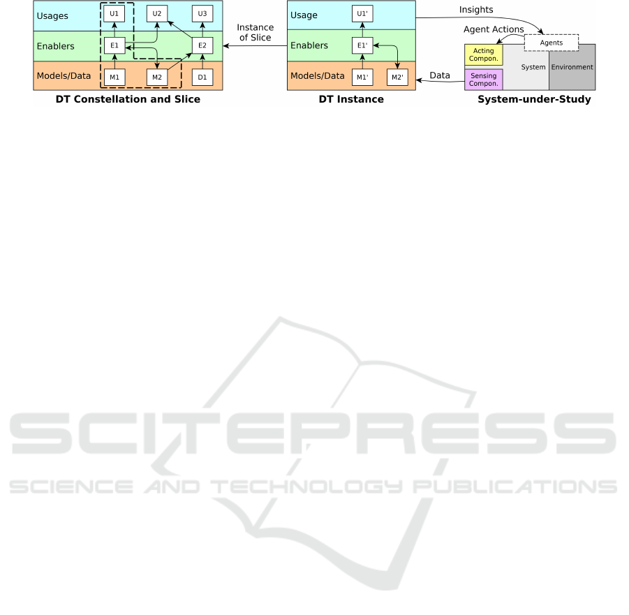
Figure 2: An overview of our conceptual structure for describing digital twins.
3.3.2 Enablers
The enablers are (conceptually) below the usages, and
are those components of the DT that operate on the
models and data in the DT and directly enable a us-
age. This definition for enablers is intentionally broad
to support many types of components serving usages
across different DT domains. For example, (Werner
et al., 2019) discuss how a predictive maintenance
usage is enabled by a state predictor/simulator based
on machine metrics. A video game engine like Unity
(https://unity.com/) enables virtual spaces for visual-
ization of personal health metrics (Mohammadi and
Taylor, 2020).
3.3.3 Models and Data
Finally, the models and data used by the DT are
grouped together on a (conceptual) layer and are both
input and output for the enablers. For example, data
could be input into a machine learning trainer (an en-
abler) to produce a neural net (a model) (Min et al.,
2019).
3.3.4 Time-scales
An essential characteristic of DTs is that the communi-
cation between the SUS and the DT for a usage most
likely occurs at different time-scales. A usage’s in-
sights, actions, and data communication could each
occur as slower-than-real-time or real-time, and the
usage itself could rely on slower-than-real-time, real-
time, or even faster-than-real-time reasoning.
If an insight, action, or data collection step is
slower-than-real-time, that part of the cycle is not
real-time “live” but instead the DT periodically re-
ceives data from the SUS, or issues insights or ac-
tion to the SUS for some future time. For example,
a predictive maintenance DT could receive real-time
machine sensor information, but issue insights to a
scheduling agent to modify worker routines for a later
shift (Werner et al., 2019).
A real-time time-scale is where the action or data
collection is communicated between the SUS and the
DT for reasoning and provoking of an action on the
SUS within a short-scale (most likely sub-second)
time-frame. All examples of real-time control by a
DT include this time-scale, such as production-time
control (Zhuang et al., 2018).
Finally, the faster-than-real-time time-scale is
where the enablers for a usage perform predictive sim-
ulation to predict the state of the SUS in the (near-
)future. This faster-than-real-time simulation is then
used to produce insights and actions, such as slower-
than-real-time insights or actions like workstation lay-
out modifications (Malik and Bilberg, 2018), or real-
time trajectory optimization for crane control (Zhid-
chenko et al., 2018).
The collected examples in Section 4 (and on-
line (Oakes et al., 2020)) demonstrate how a DT solu-
tion most likely involves communication at all three
time-scales. The time-scale characteristic of DT com-
munication is explicitly expressed in our characteris-
tics, as practitioners could have the belief that a “true”
DT is only those that have “hard real-time” control
connections. We leave this particular interpretation
open for now, but our conceptual structure provide
the guidelines for experience reports such that future
research can discuss classifications in each practitioner
domain.
3.4 Constellations and Slices
One benefit of DTs is that once there is a critical mass
of high-quality enablers, models, and data, then multi-
ple usages become possible (Uhlemann et al., 2017).
Our conceptual structure denotes a DT constellation as
an agglomeration of all related models, data, enablers,
and usages that are used in the DT activities involving
a particular type of SUS, as shown on the left-hand
side of Figure 2.
A particular enabler may support multiple usages
within a constellation, and a model or piece of data
may be operated upon by multiple enablers. For ex-
ample, in Figure 2, enabler E1 supports usages U1
and U2, while enabler E2 supports usages U2 and U3.
Figure 3 presents a constellation for the experience
report in Section 2.
A DT slice is then the selection of components in
a DT constellation to support a particular usage. For
example, in Figure 2 one out of a possible three DT
MODELSWARD 2021 - 9th International Conference on Model-Driven Engineering and Software Development
184

slices is represented by the dashed lines around the
components which support usage U1. This slice can
then be implemented by any number of DT instances,
as represented in the middle of Figure 2, where prime
marks denote an instance of a slice. These slices there-
fore reinforce the modular nature of DTs, where the
enablers and models and data are reused for multiple
usages within a DT constellation.
Note that the DT constellation and DT slice are
conceptual objects to group components of the DT
activity for description purposes. Constellations and its
slices likely do not exist either physically or virtually
in the practitioner’s DT solution. In contrast, the DT
instance must be running on a computational device,
and the connected SUS must exist in the physical or
the virtual world.
3.4.1 Life-cycle Stages
DTs in the literature operate at various stages in the
life-cycle of a system. These stages are not fixed
and have domain-specific terms such as design, pre-
production, and production (S
¨
oderberg et al., 2017),
or ideation, realization, and utilization (Leinen, 2017).
(Pokharel and Mutha, 2009) also consider a reclama-
tion life-cycle stage, involving disassembly and re-use
in new products.
As the SUS moves through the stages of its life-
cycle, the usages of its connected DTs and the scope
of the SUS will likely change. For example, during
the ideation phase a DT may offer optimization and
visualization usages for product design (Tao et al.,
2019). During later stages, the SUS may then expand
to encompass the manufacturing facility and worker’s
routines, where the optimization usage must then con-
sider new objectives and parameters (S
¨
oderberg et al.,
2017).
Our conceptual structure thus suggests a report of a
DT solution includes the usages and scope for the SUS
(if different) for each of the life-cycle stages in the
solution. This assists researchers and practitioners in
classifying their DT solutions, identifying challenges,
and recommending useful enablers for each life-cycle
stage. For example, assembly and disassembly pro-
cesses for a product may share enablers provided by a
DT solution.
3.4.2 Evolution
As practitioners build up techniques and tools and
discover new DT requirements, the solution and its
constellation evolves to support further usages across
the life-cycle stages, and between different product
versions. For example, (S
¨
oderberg et al., 2017) report
seven DT usages spread across three phases of the
product life-cycle but not the order of their develop-
ment.
Providing information on the evolution of the con-
stellation could enable further classifications and re-
search insights into DTs. An example could be identi-
fication of whether the digital model (Kritzinger et al.,
2018) used in the design stage is often first transformed
into a digital shadow (as in (Min et al., 2019)), or
whether it is directly used as the basis for a digital
twin. Another example would be scheduling the im-
plementation of design-stage usages in parallel with
the pre-production and production stage usages.
3.5 Essential Characteristics
This section provides a summary of the essential as-
pects of our conceptual structure to provide a struc-
tured list for the precise reporting of DT characteristics
in future experience reports.
We present here brief details from the collabora-
tive assembly experience report detailed in Section 2.
This demonstrates that even with a high-quality report,
there are still characteristics that remain unclear such
as the time-scale of certain insights and actions, as
denoted with a question mark. As discussed in Sec-
tion 2, these missing details hamper the classification
and capabilities of this experience report.
Due to space reasons, only the briefest sketch of
relevant details is presented here. This summary is far
less than the level of detail we expect practitioners to
provide in their experience reports.
System-Under-Study:
The scope of the SUS in-
cluding the system, environment, and agents. A collab-
orative assembly process, involving humans, robots,
workstation, an assembly station, production steps, and
product parts.
Multiplicities:
How many DTs and SUS entities
are involved in the solution, and their relationship. DT
instances exist for each workstation in the assembly
process.
Usages:
The activities the DT is used for. Task
allocation between humans and robots, layout genera-
tion for the workstation, ergonomic analysis, and robot
code generation.
Enablers:
The DT components which use models
and data to support usages. A visualization engine for
the layout usage, task planner for allocation, worksta-
tion simulator, code generator for robot programming.
Models and Data:
The input and output for en-
ablers. Computer-aided design (CAD) models for hu-
man, robot, and workstation, motion data from three-
dimensional camera, shop-floor data (inventory, etc.),
production plans.
Slices:
Relationships between usages, enablers,
Improving Digital Twin Experience Reports
185
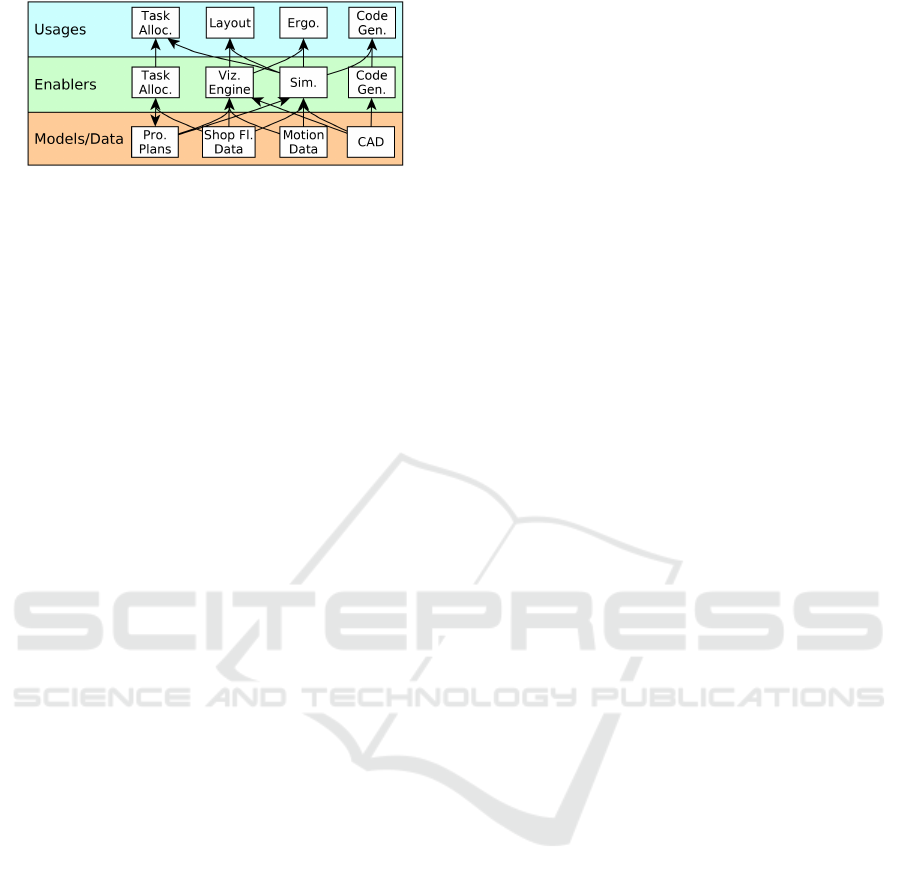
Figure 3: A possible DT constellation for (Malik and Bilberg,
2018).
and models and data. Our impression of the DT con-
stellation for this report is seen in Figure 3.
Fidelity Considerations:
Explanations of fidelity
of DT to SUS with respect to each DT usage. For
layout and ergonomic usages, workstation and robot
geometry must be accurate within a few millimeters(?).
Human model corresponds to a typical Danish worker.
For task allocation usage, shop floor data has slight
variations(?).
Data Communicated:
What is transferred from
SUS to DT.
Manual:
Production requirements(?)
Auto: Inventory data, robot data.
Insights and Actions:
What is communicated
from DT to SUS.
Insights:
Task allocations,
workspace layout, assembly procedure and configura-
tion. Actions: Robot code(?).
Time-scale:
The time-scale of the data, insights,
actions, and simulations used.
Slower-than-real-time:
Production requirements, task allocations, workspace
layout, assembly procedure and configuration, robot
code. (Unclear, could be real-time on “production
changeover”)
Real-time:
Inventory and robot data.
Faster-than-real-time:
Task allocation and ergonomic
usages.
Acting Components:
Add./modif. to SUS en-
abling DT actions and insights. Not reported.
Sensing Components:
Add./modif. to SUS en-
abling DT data collection. Not reported.
Life-cycle Stages:
The stages of the life-cycle that
the DT is utilized for, the usages for each, and (if vary-
ing) the scope of the SUS.
Design:
Task allocation,
workstation layout, ergonomic analysis.
Development:
Workstation layout (?).
Operation:
Task allocation,
workstation layout, ergonomic analysis, code genera-
tion.
Evolution:
How the DT evolves over the DT
project timeline. Visualization developed, then event-
based simulation.
3.6 Threats to Validity
A major threat to validity of our conceptual structure
is whether the fourteen characteristics we have pre-
sented here are essential for practitioners to communi-
cate in their experience reports. This threat has been
addressed by selecting those common characteristics
which were discussed (at least briefly) in the consid-
ered experience reports in the literature (Oakes et al.,
2020).
A related threat is the applicability to DTs in dif-
ferent domains, and that it is insufficiently detailed
enough for practical usage. This threat is partially
addressed by providing examples of the conceptual
structure’s usage for multiple experience reports, both
in this paper and online (Oakes et al., 2020). The con-
ceptual structure is also at a general level, including
broad characteristics such as enablers and models and
data.
Our selection of relevant characteristics will never
be sufficient for all domains, as many other dimensions
are relevant for stakeholders in particular domains. A
few examples include the particular technology solu-
tions used, the business case and stakeholders for each
usage, or cyber-security considerations. It is there-
fore our hope that researchers and practitioners will
use our conceptual structure as a starting point, and
eventually coalesce around a particular set of defined
characteristics for each individual DT domain.
4 APPLICATION EXAMPLES
This section examines four selected works from the lit-
erature described as digital twins (DTs), using our con-
ceptual structure to produce a table of characteristics
(Table 1). This section is to demonstrate applicability
to DT solutions in multiple domains, and highlight
how this structure ensures that these characteristics
are reported to assist with further classification and
insights. As a visual guide, missing entries are marked
in bold, while unclear information is marked in italics.
Similar to Section 3.5, only the briefest of details are
reported here due to space considerations.
Boat Avatar:
(Wuest et al., 2015) describe a “prod-
uct avatar” approach where the information from sen-
sors on leisure boats is used to provide services to man-
ufacturers and boat owners. For example, maintenance
information is collected during the winter season when
boats are in storage, and service offers are relayed to
service providers and boat owners to offer repairs or
refurbishment.
(Uhlenkamp et al., 2019) identifies this experience
report as a “digital twin application scenario”. How-
ever, this report is difficult to classify according to
(Kritzinger et al., 2018) as it mostly describes a digital
shadow where no automatic actions are commanded.
We have identified one possible action: boat infor-
MODELSWARD 2021 - 9th International Conference on Model-Driven Engineering and Software Development
186

Table 1: Four digital twin experience reports as presented in our conceptual structure.
Expr.
Report
Boat Avatar (Wuest et al., 2015) Cyber Guided
Vehicle (Bottani
et al., 2017)
Oil and Gas
Drilling (Mayani et al.,
2018)
Petrochemical Optimization (Min
et al., 2019)
System-
under-study
Leisure boats and stakeholders
(owners, manufacturers, social
networks) (?).
Auto. guided vehicle
(AGV) in job-shop
prod. system.
Performance of and forces
on drilling rig.
Catalytic cracking unit in
petrochemical production line.
Multipl. DT instances per boat. DT instances per
prod. system.
DT instances per drill site. DT instances per unit.
Usages Optimizing design/production,
enhancing boat experience, upgrade
services.
Optimizing policy
for system profit,
visualization.
Planning, training, operation
forecasting.
Production optimization.
Enablers Production decision support, web
presence, maintenance recommenders.
Simulator, AGV
controller.
Sim. of performance and
forces, auto. monitoring.
“Profit and market modelling
systems”, “sim. and opt. systems”,
machine-learning algs.
Models &
Data
Data from boat, predictive models for
maintenance recommenders.
Model of shop, AGV
code, prod. data.
Sensor data, hydraulic and
mechanical models.
Machine learning models, historic
data.
Slices [Omitted for space] Same slice for
usages.
[Omitted for space] Unclear.
Fidelity
Consid.
Realistic for optimizing and services,
less realistic for boat experience. Not
explicit.
Realistic for
optimization, less
realistic for viz. Not
explicit.
Highly realistic for planning
and forecasting, realistic for
training. Not explicit.
Realistic. Data must be cleaned
and aligned before processing.
Data
Comm.
Auto: Assorted boat conditions, such
as battery/fuel level, current weather,
maintenance status, position, etc.
None (possibly
code?).
Auto: Temperature, pressure,
etc.
Production plans, production line
data.
Ins. & Act. I: Boat info., service recommendations
& offers. A: Posting to social
networks(?).
I/A(?): AGV
controller code.
I: Performance reports. A:
Drill control signals.
I: ”Analysis data” and
recommendation info. A: Control
instructions.
Time-Scale Slower-t-r-t insights, real-time data,
real-time posting to social networks
(?).
Slower-t-r-t. Slower-t-r-t for reports &
training, real-time for
control, faster-t-r-t for
sim.(?).
Slower-t-r-t historical data and
insights, real-time data and control
actions.
Acting
Compon.
Created web platform integration. No compon.
additions reported.
No compon. additions
reported.
“Industrial IoT systems”, such as
“electric and electronic circuits”
Sensing
Compon.
Product Life-cycle Management
system, data integration layer
No compon.
additions reported.
No compon. additions
reported.
Measuring instruments, “sampling,
preprocessing and injection
systems”, monitors and recorders.
Life-cycle
Stages
Ideation, realization, utilization,
reclamation. SUS: No manufacturers
in middle stages (?).
Utilization. Ideation, realization,
utilization.
Utilization.
Evolution Usages created, then data connection,
then insight/action connection.
Not reported. Used for training, then used
for control(?).
Basic DT constructed, then trained
on existing data, then connected to
SUS.
Class. DS/DT (?) DS/DT (?) (versus
DT by (Kritzinger
et al., 2018))
DT DT (versus DS by (Fuller et al.,
2020))
mation could be automatically posted to social net-
works. Further clarification by the authors is therefore
required to classify the DT solution as a digital twin.
As well, it is difficult to understand the precise
system-under-study (SUS), insights, and actions in-
volved. In particular, in Table 1 we have placed the
boat manufacturers and the boat owners as agents and
as part of the SUS, but this may not be the intention of
Improving Digital Twin Experience Reports
187

the report authors.
Cyber Guided Vehicle:
(Bottani et al., 2017) detail
the creation of a simulation for an Automated Guided
Vehicle (AGV) in the context of a job-shop where the
AGV transports materials to be assembled. The same
code from the AGV runs inside the simulation, which
is used to optimize the AGV’s policies for maximum
profit.
This report also lacks relevant details about the DT
solution. In particular, Table 1 in (Kritzinger et al.,
2018) claims that this solution is a digital twin. How-
ever, from our reading the only communication be-
tween the digital object and the physical AGV would
be the policies or AGV code. It is unclear whether this
communication would be automatic to and from the
AGV to the digital object and how often this would oc-
cur. This experience report may thus describe a digital
shadow.
Oil and Gas Drilling:
(Mayani et al., 2018) report
the successes of using DT technology by a Norwegian
oil and gas technology provider. Four uses of the DT
technology at three oil and gas wells for monitoring
and training purposes are discussed, as well as the cost-
and time-saving benefits. As drill parameters are opti-
mized based on the digital object, the overall solution
is a digital twin by the classification by (Kritzinger
et al., 2018). However, the training usage of the solu-
tion may not lead to automated control actions with
the SUS, thus indicating that the DT solution acts as a
digital shadow for some usages.
Petrochemical Optimization:
(Min et al., 2019)
provide an excellent report on the use of digital twins
for optimization of petrochemical production. Data
from factory sensors undergoes cleaning such as time
series unification, before it is used alongside historical
data for machine learning training and prediction. The
DT solution determines recommendations and control
actions to improve the economic potential of the plant,
such as by increasing the yield of light oil.
As this report explicitly mentions the use of con-
trol actions on the plant, our reading suggests it is a
digital twin as per the classification by (Fuller et al.,
2020). However, this report is classified as a digital
shadow, possibly due to the ambiguous sentence “[the
output], real-time recommended control information,
is viewed by operators first before being utilized in
the production system”. It is therefore not clear if the
control information is presented as insights, or is an
action on the system. The capabilities and classifica-
tion of this DT solution would therefore be clarified
when presented in our conceptual structure.
5 RELATED WORK
Structured DT Definitions.
(Grieves and Vickers,
2017) define DT Prototypes, DT Instances, and DT Ag-
gregates. DT Prototypes exist only in the design stage
of a system, before being realized as a Physical Twin.
Each Physical Twin is then monitored and acted upon
by a DT Instance. A collection of DT Instances is a DT
Aggregate. This structuring parallels our own, where
DT Prototypes would be the models and data involved
in a DT Constellation while the DT Constellation op-
erates in the design stage of a system. The concept of
the DT Instance is the same as a particular instance of
a DT communicates with a system-under-study (SUS).
Our structure requests that the multiplicity of the DTs
with relation to the SUS be explicit for clarity, such as
whether multiple DT instances are aggregated to form
a DT of a larger system.
(Tao et al., 2018b) present a five-component struc-
ture for relating DTs and the SUS: a) the physical
entity model which is the SUS including sensors and
actuators, b) the virtual equipment model including
models and behaviour description, c) a services model
with the usages of the DT and include quality infor-
mation, d) a DT data model to structure the domain
knowledge of the DT, and e) a connection model which
structures the incoming or outgoing data from the DT,
such as variable type and sampling interval. In con-
trast, our structure is at a higher level of abstraction
and is not about technical details but only a summary
of the characteristics and capabilities.
Further work by (Tao et al., 2019) focuses on the
use of DTs for product design and manufacturing, such
as enabling technologies for DTs and a ‘V-cycle’ for
validating and verifying product design. Also relevant
is the investigation of the steps of building the DT
for product design, which is similar to our concept
of evolution. These steps involve the creation of the
virtual product and its connection with the physical
product, where the DT solution moves from a digital
model through a digital shadow stage to become a
digital twin.
(Worden et al., 2020) take a mathematical approach
to DTs where mirrors are defined which replicate the
behaviour of a system in an environment and context
according to a fidelity measure. These Turing mirrors
must provide the same answers to questions as the
original physical system. This is relevant to our work
as it formalizes our fidelity characteristic.
Digital Twin Aspects/Characteristics.
(Boschert
and Rosen, 2016) discuss the use of DTs for simu-
lation throughout a system’s life-cycle stages and the
need for DTs to be modular to fit into value chains.
MODELSWARD 2021 - 9th International Conference on Model-Driven Engineering and Software Development
188

The DT purpose may also change due to the current
life-cycle stage of the system or the maturity of the DT
itself.
Similar to our work, (Uhlenkamp et al., 2019)
present seven characteristics of DTs. Goals refer to
the abilities of the DT and include information ac-
quisition, information analysis, decision and action
selection and action implementation. Users focus on
one user or multiple stakeholders. Life-cycle focus
can likewise be a single stage or multiple. A system
focus can be component, subsystem, system, or system
of systems. Data sources for a DT include measure-
ments, virtual data (including simulation data), and
(expert) knowledge. Data integration levels replace
the classification of (Kritzinger et al., 2018) with man-
ual, semi-automated, and automated. Finally, their
characteristics include authenticity which we refer to
in our conceptual structure as fidelity. While relevant,
we demonstrate in Section 2 that further characteris-
tics and detail may be required in current experience
reports to apply their structure.
According to (Madni et al., 2019), DTs are an en-
abling technology in the next steps of model-based
system engineering (MBSE). A comprehensive exami-
nation of DTs within the context of MBSE is presented,
along with a classification of DT maturity through-
out the life-cycle of the system of pre-DT, DT, adap-
tive DT, and intelligent DT. Relevant to our work is
a list of characteristics which separates DT from tra-
ditional computer-assisted design (CAD) models, in-
cluding specificity, understanding assumptions and
performance, and traceability among others.
(van der Valk et al., 2020) propose a DT taxonomy
with characteristics and relationships, while (Jones
et al., 2020) details a literature survey. These works
propose further characteristics of DTs, but do not cre-
ate a conceptual structuring.
6 CONCLUSION
This paper presents a conceptual structure for describ-
ing digital twins (DTs) such that practitioners can struc-
ture their reporting and ensure they describe essential
characteristics and capabilities in their experience re-
ports. In turn, this provides a firmer foundation for
the DT research community to gain further insights
into challenges and solutions, and offer a more precise
classification of the DT types in practice. It is our
ambition that this structure serves as a common refer-
ence to enable clear communication of DT solutions
between academic and industrial stakeholders. The
applicability of the structuring and its use in structur-
ing a report and indicating missing characteristics has
been demonstrated by expressing multiple experience
reports from the literature. This has revealed six cases
where the suggested classification differs from that of
others (Oakes et al., 2020).
ACKNOWLEDGEMENTS
This work was partly funded by Flanders Make vzw,
the strategic research centre for the Flemish manufac-
turing industry.
REFERENCES
Boschert, S. and Rosen, R. (2016). Digital twin—the sim-
ulation aspect. In Mechatronic Futures, pages 59–74.
Springer.
Bottani, E., Cammardella, A., et al. (2017). From the cyber-
physical system to the digital twin: the process de-
velopment for behaviour modelling of a cyber guided
vehicle in m2m logic. XXII Summer School Francesco
Turco – Industrial Systems Engineering, pages 1–7.
Chhetri, S. R., Faezi, S., et al. (2019). QUILT: quality
inference from living digital twins in iot-enabled man-
ufacturing systems. In Proceedings of International
Conference on Internet of Things Design and Imple-
mentation, pages 237–248. ACM.
Fuller, A., Fan, Z., et al. (2020). Digital twin: Enabling
technologies, challenges and open research. IEEE
Access, 8:108952–108971.
Grieves, M. and Vickers, J. (2017). Digital twin: Mitigat-
ing unpredictable, undesirable emergent behavior in
complex systems. In Transdisciplinary perspectives on
complex systems, pages 85–113. Springer.
Jones, D., Snider, C., et al. (2020). Characterising the digital
twin: A systematic literature review. CIRP Journal of
Manufacturing Science and Technology, 29:36–52.
Kritzinger, W., Karner, M., et al. (2018). Digital twin in man-
ufacturing: A categorical literature review and classifi-
cation. IFAC-PapersOnLine, 51(11):1016–1022.
Leinen, R. (2017). Driving the digital enterprise in prod-
uct development and manufacturing. Presented at 6th
CSIR Conference.
Liu, Y., Zhang, L., et al. (2019). A novel cloud-based frame-
work for the elderly healthcare services using digital
twin. IEEE Access, 7:49088–49101.
Madni, A. M., Madni, C. C., and Lucero, S. D. (2019).
Leveraging digital twin technology in model-based
systems engineering. Systems, 7(1):7.
Malik, A. A. and Bilberg, A. (2018). Digital twins of human
robot collaboration in a production setting. Procedia
manufacturing, 17:278–285.
Mayani, M. G., Svendsen, M., and Oedegaard, S. I. (2018).
Drilling digital twin success stories the last 10 years. In
SPE Norway One Day Seminar, pages 1–13. Society of
Petroleum Engineers, Society of Petroleum Engineers.
Improving Digital Twin Experience Reports
189

Miller, A. M., Alvarez, R., and Hartman, N. (2018). Towards
an extended model-based definition for the digital twin.
Computer-Aided Design and Applications, 15(6):880–
891.
Min, Q., Lu, Y., et al. (2019). Machine learning based
digital twin framework for production optimization
in petrochemical industry. International Journal of
Information Management, 49:502–519.
Mohammadi, N. and Taylor, J. (2020). Knowledge discovery
in smart city digital twins. In Proceedings of the 53rd
Hawaii International Conference on System Sciences,
pages 1656–1664. Hawaii International Conference on
System Sciences.
Oakes, B., Parsai, A., et al. (2020). Digital Twin experience
report analysis. https://msdl.uantwerpen.be/git/bentley/
2020.MODELSWARD.DT.
Pokharel, S. and Mutha, A. (2009). Perspectives in reverse
logistics: a review. Resources, Conservation and Recy-
cling, 53(4):175–182.
Rasheed, A., San, O., and Kvamsdal, T. (2020). Digital
twin: Values, challenges and enablers from a modeling
perspective. IEEE Access, 8:21980–22012.
Ruohom
¨
aki, T., Airaksinen, E., et al. (2018). Smart city
platform enabling digital twin. In 2018 International
Conference on Intelligent Systems (IS), pages 155–161.
IEEE.
S
¨
oderberg, R., W
¨
armefjord, K., et al. (2017). Toward a
digital twin for real-time geometry assurance in indi-
vidualized production. CIRP Annals, 66(1):137–140.
Tao, F., Cheng, J., et al. (2018a). Digital twin-driven prod-
uct design, manufacturing and service with big data.
The International Journal of Advanced Manufacturing
Technology, 94(9-12):3563–3576.
Tao, F., Sui, F., et al. (2019). Digital twin-driven product
design framework. International Journal of Production
Research, 57(12):3935–3953.
Tao, F., Zhang, M., et al. (2018b). Digital twin driven prog-
nostics and health management for complex equipment.
CIRP Annals, 67(1):169–172.
Traor
´
e, M. K. and Muzy, A. (2006). Capturing the dual rela-
tionship between simulation models and their context.
Simulation Modelling Practice and Theory, 14(2):126–
142.
Uhlemann, T. H.-J., Lehmann, C., and Steinhilper, R. (2017).
The digital twin: Realizing the cyber-physical produc-
tion system for industry 4.0. Procedia CIRP, 61:335–
340.
Uhlenkamp, J.-F., Hribernik, K., et al. (2019). Digital twin
applications: A first systemization of their dimensions.
In 2019 IEEE International Conference on Engineer-
ing, Technology and Innovation (ICE/ITMC), pages
1–8. IEEE.
van der Valk, H., Haße, H., et al. (2020). A taxonomy of
digital twins. In AMCIS 2020 Proceedings. AIS.
Werner, A., Zimmermann, N., and Lentes, J. (2019). Ap-
proach for a holistic predictive maintenance strategy by
incorporating a digital twin. Procedia Manufacturing,
39:1743–1751.
Worden, K., Cross, E. J., et al. (2020). On digital twins, mir-
rors and virtualisations. In Barthorpe, R., editor, Model
Validation and Uncertainty Quantification, Volume 3,
pages 285–295. Springer.
Wuest, T., Hribernik, K., and Thoben, K.-D. (2015). Ac-
cessing servitisation potential of PLM data by applying
the product avatar concept. Production Planning &
Control, 26(14-15):1198–1218.
Zeigler, B. P., Kim, T. G., and Praehofer, H. (2000). Theory
of modeling and simulation: integrating discrete event
and continuous complex dynamic systems. Academic
press, San Diego.
Zhidchenko, V., Malysheva, I., et al. (2018). Faster than
real-time simulation of mobile crane dynamics using
digital twin concept. In Journal of Physics: Conference
Series, volume 1096, page 012071. IOP Publishing.
Zhuang, C., Liu, J., and Xiong, H. (2018). Digital twin-based
smart production management and control framework
for the complex product assembly shop-floor. The In-
ternational Journal of Advanced Manufacturing Tech-
nology, 96(1-4):1149–1163.
MODELSWARD 2021 - 9th International Conference on Model-Driven Engineering and Software Development
190
