
Performance Aspects of Correctness-oriented Synthesis Flows
Fritjof Bornebusch
1
, Christoph L
¨
uth
1,2
, Robert Wille
1,3,4
and Rolf Drechsler
1,2
1
Cyber-Physical Systems, DFKI GmbH, Bremen, Germany
2
Mathematics and Computer Science, University of Bremen, Germany
3
Integrated Circuit and System Design, Johannes Kepler University Linz, Austria
4
Software Competence Center Hagenberg GmbH (SCCH), Hagenberg, Austria
Keywords:
Hardware Designs, Proof Assistants, Functional HDLs, Hardware Synthesis, MIPS Processor.
Abstract:
When designing electronic circuits, available synthesis flows either focus on accelerating the synthesized
circuit or correctness. In the quest for ever-faster hardware designs, the correctness of these designs is often
neglected. Thus, designers need to trade-off between correctness and performance. The question is how large
the trade-off is? This work presents a systematic comparison of two representative synthesis flows, the LegUp
HLS framework as a representative for flows focusing on hardware acceleration, and a flow based on the
proof assistant Coq focusing on correctness. For evaluation purposes, a 32-bit MIPS processor synthesized
using the two flows, and the final HDL implementations are compared regarding their performance. Our
evaluation allows a quantitative analysis of the trade-off, showing that correctness-oriented synthesis flows are
competitive concerning performance.
1 INTRODUCTION
Electronic circuits have become more and more com-
plex over time. The goal of synthesis flows is either
to synthesize accelerated circuits which have a high
performance or correct ones which guarantee correct-
ness properties. As synthesis flows with an empha-
sis on acceleration often do not provide the ability to
formulate correctness proofs, these design flows are
a severe issue when applied in safety-critical systems
such as cars, airplanes, or medical devices. This com-
parison leads to the question of whether both flows
can be combined to get the best of both worlds.
To address this question, we first take a look at
synthesis flows with an emphasis on acceleration. To
tackle the synthesis of faster hardware designs, syn-
thesis flows like Bambu (Pilato and Ferrandi, 2013),
DWARV (Nane et al., 2012), or LegUp (Canis et al.,
2013; Canis et al., 2016) evolved (in the following
called acceleration-oriented synthesis flows). These
flows start with a model written in a Domain-specific
language (DSL) to describe hardware designs that are
embedded into the C programming language. After
the model is implemented, it is synthesized into a low-
level implementation in a hardware description lan-
guage (HDL) at the Register-Transfer-Level (RTL),
e.g., Verilog. During the automatic synthesis process,
different optimizations like loop or functional pipelin-
ing (Canis et al., 2013; Hwang et al., 1991) are per-
formed to accelerate the final implementation.
One problem with these synthesis flows is the
missing definition of a synthesis scheme (Eisen-
biegler and Kumar, 1995; Baaij and Kuper, 2013) and
the resulting lack of property verification. In general,
it is unclear (1) how the implementation is generated
from the model in detail; (2) whether the semantics
of the model are correctly represented by the seman-
tics of the implementation; and (3) how to track and
verify properties stated at the specification level in the
implementation.
In contrast, synthesis flows with an emphasis on
verification like Kami (Choi et al., 2017) or the
one based on Coq (Bertot and Cast
´
eran, 2004) and
CλaSH (Baaij et al., 2010) as introduced in (Borneb-
usch et al., 2020) start with a specification in a for-
mal language that allows the verification of functional
properties about the hardware design (in the follow-
ing called correctness-oriented synthesis flows). Af-
ter the specified behavior was verified, an RTL im-
plementation is synthesized automatically. This way,
these flows guarantee a correct transformation of the
semantics of the specification to the final implemen-
tation and, hence, ensure the verified properties hold
on all levels.
76
Bornebusch, F., Lüth, C., Wille, R. and Drechsler, R.
Performance Aspects of Correctness-oriented Synthesis Flows.
DOI: 10.5220/0010235100760086
In Proceedings of the 9th Inter national Conference on Model-Driven Engineering and Software Development (MODELSWARD 2021), pages 76-86
ISBN: 978-989-758-487-9
Copyright
c
2021 by SCITEPRESS – Science and Technology Publications, Lda. All rights reserved

However, while these approaches can guarantee
correctness, it remains unclear how the performance
of the resulting designs compares to the performance
of designs obtained by the acceleration-oriented syn-
thesis flows reviewed above. In fact, it is intuitive to
assume that a focus on verification may harm this per-
formance. But unfortunately, this possible trade-off
has not been addressed in detail yet. While anecdotal
evidence suggests correctness-oriented flows can be
competitive with respect to performance, we present
a systematic analysis by comparing the design of a
non-trivial circuit with two representative flows from
each camp.
The missing trade-off leaves designers with the
question of whether they should focus on correctness
(motivating the utilization of a correctness-oriented
synthesis flow) or on performance (motivating the uti-
lization of an acceleration-oriented synthesis flow).
This paper addresses this question. To this end,
we investigate both design flow paradigms – using the
LegUp high-level synthesis (HLS) framework (Ca-
nis et al., 2013; Canis et al., 2016) and the syn-
thesis flow from (Bornebusch et al., 2020) as a rep-
resentative for acceleration-oriented and correctness-
oriented synthesis, respectively. We chose those flows
as they represent the most efficient (cf. (Nane et al.,
2016)) and most recent flows available thus far, im-
plementing the respective concepts. The foundation
of the investigation is a 32-bit MIPS processor (Hara
et al., 2009), which is synthesizable by LegUp. The
functional behavior of this processor is specified, ver-
ified, and synthesized using the correctness-oriented
flow, described above.
Our quantitative analysis of the processor im-
plementations gives a first impression to gauge the
trade-off between performance and correctness. Even
though there will be cases that justify the applica-
tion of the acceleration-oriented flows, our analy-
sis shows the potential of further research of apply-
ing correctness-oriented flows in an industrial set-
ting, even in cases where performance is a criti-
cal issue. Moreover, it is easier to increase the
performance of circuits synthesized by correctness-
oriented flows than to make hardware designs follow-
ing acceleration-oriented flows correct.
We do not discuss whether an acceleration-
oriented model or a correctness-oriented specification
is more user-friendly as this question is too subjective
to answer.
This work is structured as follows: first, we moti-
vate our work by describing and discussing the LegUp
synthesis flow and the considered problem we address
in this work. Section 3 describes the correctness-
oriented synthesis flow in detail and how it addresses
the considered problem. Section 4 describes our spec-
ification of the processor and how properties are veri-
fied. Section 5 evaluates and discusses the RTL im-
plementations. Finally, Section 6 summarizes this
work.
2 MOTIVATION
This section analyzes the LegUp HLS framework syn-
thesis flow (Canis et al., 2013) as a representative of
a contemporary, state-of-the-art acceleration-oriented
synthesis flow. On average, LegUp synthesizes the
fastest hardware designs, which is the reason for pick-
ing it as a representative (Nane et al., 2016). This
flow analysis shows the missing ability to verify cor-
rectness properties of models implemented for these
flows.
An available model of a 32-bit MIPS processor
is used as a running example to analyze the syn-
thesis flow implemented by the LegUp HLS frame-
work (Hara et al., 2009; ?). The MIPS architecture
describes an instruction set architecture (ISA) for a re-
duced instruction set computer (RISC) (MIPS, 2016).
2.1 The LegUp Synthesis Flow
The foundation of the LegUp framework is the LLVM
(Low Level Virtual Machine) compiler infrastruc-
ture (Lattner and Adve, 2004). LLVM is a modu-
lar compiler infrastructure for optimized code gen-
eration. A model is transformed into LLVMs inter-
nal intermediate representation, which is a machine-
independent assembly language using the Clang com-
piler front-end and later optimized by a series of built-
in compiler optimizations. LegUp extends the LLVM
backend by generating Verilog code instead of Ma-
chine code (Canis et al., 2013). In order to acceler-
ate hardware designs, different additional optimiza-
tions are performed during the optimization process
by LegUp, e.g., loop or functional pipelining (Canis
et al., 2013; ?).
These optimizations aim to identify behavior that
can be accelerated. Whether an optimization can be
performed and , therefore, result in an implementa-
tion that satisfies the required performance properties
depends on the used model.
For modeling designs, LegUp defines a Domain-
specific language embedded into the C programming
language. Two modes are provided to synthesize
a model. The first mode is the generation of a
hybrid processor/accelerator architecture. The de-
scribed behavior of a model is compiled and exe-
cuted on a dedicated processor that profiles its ex-
Performance Aspects of Correctness-oriented Synthesis Flows
77
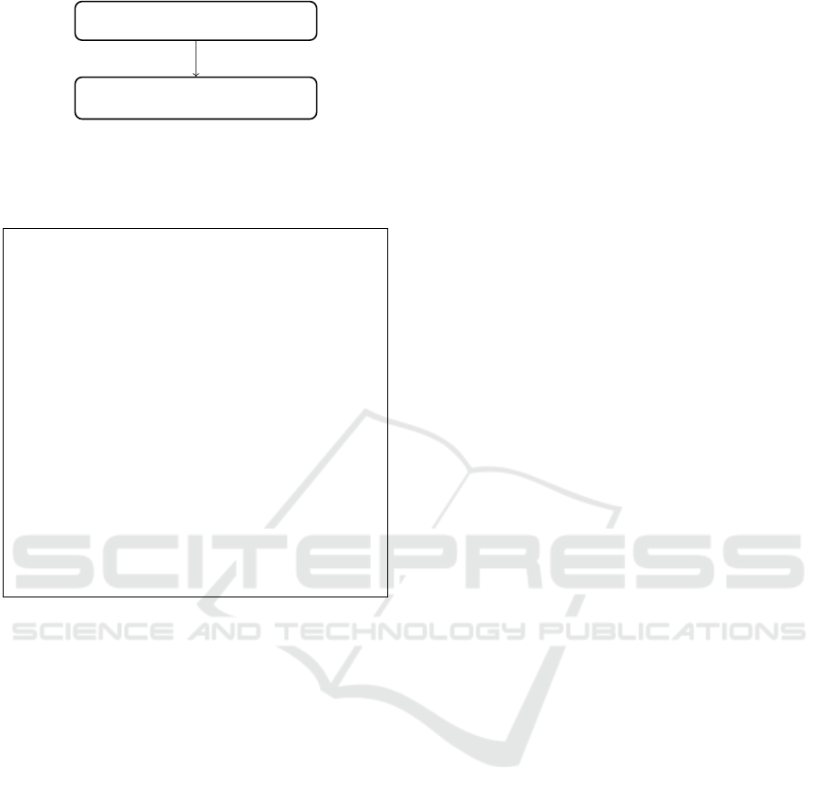
Model
in hardware DSL
Implementation
in Verilog
automatic
Figure 1: Sketched LegUp synthesis flow for pure hardware
designs. A model in a hardware DSL is synthesized into an
accelerated low-level implementation in Verilog automati-
cally.
i n s = imem [ IADDR ( pc ) ] ;
op = i n s >> 2 6 ;
s wi t c h ( op ) {
c a s e R :
f u n c t = i n s & 0 x 3 f ;
sha m t = ( i n s >> 6 ) & 0 x1 f ;
r d = ( i n s >> 11 ) & 0 x 1f ;
r t = ( i n s >> 16 ) & 0 x 1f ;
r s = ( i n s >> 2 1) & 0 x 1 f ;
s w i t c h ( f u n c t ) {
c a s e ADDU:
r e g [ r d ] = r e g [ r s ] + r e g [ r t ] ;
br e ak ;
c a s e SLL :
r e g [ r d ] = r e g [ r t ] << s h a mt ;
br e ak ;
[ . . . ]
a d d r e s s = i n s & 0 x f f f f ;
r t = ( i n s >> 16 ) & 0 x 1f ;
r s = ( i n s >> 2 1) & 0 x 1 f ;
c a s e ADDIU :
r e g [ r t ] = r e g [ r s ] + a d d r e s s ;
br e ak ;
[ . . . ]
c a s e J :
t g t a d r = i n s & 0 x 3 f f f f f f ;
pc = t g t a d r << 2 ;
br e ak ;
Listing 1: Extract from the 32-bit MIPS processor
model that contains the ADDU, SLL, ADDIU, and J
instruction (Hara et al., 2009). The model is implemented
as a state machine that iterates over the instructions. The
current instruction is separated into its parts using logical
shift and logical and operations.
ecution. After profiling, segments of the model are
selected that are accelerated by hardware implemen-
tations. The final part is re-compiling the model into
a hybrid hardware/software system (Hardware/Soft-
ware Codesign (Ha and Teich, 2017)).
The second mode is the automatic synthesis of a
model in a pure and accelerated RTL implementa-
tion, sketched in Figure 1. After the implementation
is generated, it can be synthesized on an FPGA us-
ing commercial synthesis tools. In contrast to the first
mode, constructs like dynamic memory management,
recursion, and floating-point arithmetic are not sup-
ported (Canis et al., 2013).
In this paper, we focus on the second mode. Since
the running example used in this work describes a 32-
bit MIPS processor, the model is synthesized to pure
hardware.
Example 1. In order to analyze the LegUp synthesis
flow regarding the verification of properties, we con-
sider a 32-bit MIPS processor implementation. This
implementation is already the subject of current re-
search (Hara et al., 2009; Nane et al., 2016) and is
sketched in Listing 1. The model implements a subset
of the 32-bit MIPS standard instruction set, roughly
40 instructions. It also provides an implementation of
a program that is a set of bit-vectors and follows the
bit order for instructions stated by the 32-bit MIPS
instruction specification (MIPS, 2016).
According to the program counter, each instruc-
tion is processed in one iteration and is read from the
instruction array. It is separated into its parts, e.g.,
the operation code, function code, or operands. Af-
ter separation, the instruction is processed according
to its operation code or function code. The program
counter is changed after instruction execution so that
the next instruction is read from the instruction ar-
ray. The model also contains a register file storing
32 entries and a data memory storing 64 entries. The
execution of the iterations is stopped by a dedicated
instruction (syscall 10), which means exit and is part
of the program.
2.2 Considered Problem
LegUp implements a new LLVM backend to syn-
thesize hardware designs to Verilog implementa-
tions (Canis et al., 2013). LegUp’s input language
defines a sequential execution scheme, but hardware
designs define a parallel one. To formally describe
the transformation of a sequential scheme into a par-
allel one, synthesis schemes (Eisenbiegler and Kumar,
1995; Baaij and Kuper, 2013) can be used. Accord-
ing to the LegUp authors (Canis et al., 2013), the
transformation from LLVM’s internal representation
language to Verilog does not follow such a synthe-
sis scheme. The same goes for synthesis flows im-
plemented by Bambu (Pilato and Ferrandi, 2013) and
DWARV (Nane et al., 2012). As a result, it is unclear
how properties formulated at the model level relate to
the implementation and how one could verify them.
Moreover, it is unclear how to formulate properties
in the hardware DSL because of its embedding into
C. While there are tools to state and verify properties
of C programs, such as Frama-C (Cuoq et al., 2012)
or Astr
´
ee (Cousot et al., 2005), these tools assume a
compiler behaving according to the semantics defined
by the C standard (CStandard, 1999). These assump-
tions are not the case for hardware designs as just de-
scribed.
The missing ability to verify properties of mod-
els using the LegUp synthesis flow leads to the fol-
lowing questions. First, can we synthesize the 32-bit
MIPS processor with a different synthesis flow that al-
MODELSWARD 2021 - 9th International Conference on Model-Driven Engineering and Software Development
78

lows us to prove its correctness? Second, what would
be the performance of the final implementation com-
pared to the implementation synthesized by LegUp?
3 CORRECTNESS-ORIENTED
SYNTHESIS FLOWS
In contrast to the acceleration-oriented synthesis
flows just introduced, there are other synthesis flows
like the correctness-oriented flows implemented by
Kami (Choi et al., 2017) or (Bornebusch et al., 2020).
In this section, we discuss and evaluate both flows to
address the considered problem.
The idea of formally describing hardware us-
ing higher-order logic to prove correctness properties
(formal synthesis) is not new (Kumar et al., 1996;
Gordon et al., 2006; Hanna et al., 1989). Higher-
order logic was used to avoid the combinatorial ex-
plosion of test vectors to ensure correctness and use
symbolic reasoning instead. One of the first frame-
works using this methodology were LAMBDA/DIA-
LOG (Finn et al., 1989) and VERITAS (Hanna et al.,
1989). Elaborating this methodology further descrip-
tion languages using higher-order logic, such as Hard-
ware ML (HML) (O’Leary et al., 1993) and Blue-
spec (Arvind, 2003; ?), were invented. The inven-
tion of Bluespec resulted in a hardware description
language embedded into the proof assistant Coq to
provide an automatic synthesis process that extracts
a low-level implementation from a verified specifica-
tion (Choi et al., 2017).
Kami and the Coq/CλaSH flow rely on the proof
assistant Coq (Bertot and Cast
´
eran, 2004; Chlipala,
2013) to specify and verify hardware designs and syn-
thesize them afterwards in an implementation auto-
matically. Coq specifies a functional behavior us-
ing the Calculus of Inductive Constructions (CiC).
This formal language combines higher-order logic
and a richly-typed functional programming language,
called Gallina. As higher-order logic is too expres-
sive for automatic reasoning, a separated tactic lan-
guage (Delahaye, 2000), called L
tac
, is provided to
let the engineer guide Coq’s reasoning engine through
the proof. Properties about the specified behavior are
proven in this tactic language. As the engineer guides
the reasoning process, proof assistants are also called
interactive theorem provers. The synthesis flow of
both Kami and the one proposed in (Bornebusch et al.,
2020) is sketched in Figure 2.
To our knowledge, Kami was the first project that
proposes a formal processor specification extracted to
a low-level implementation. Kami embeds a Domain-
specific language (hardware DSL) into Gallina to de-
Specification
in Coq
Model
in Bluespec or CλaSH
Implementation
in VHDL or Verilog
automatic
automatic
Figure 2: The correctness-oriented synthesis flows start
with a specification using the proof assistant Coq. From
the specification, a model in Bluespec (Kami) or CλaSH
((Bornebusch et al., 2020)) is extracted. The model is fi-
nally synthesized to an RTL implementation, e.g., in VHDL
or Verilog.
scribe hardware designs functional (Choi et al., 2017).
This language is based on the Bluespec hardware de-
scription language (Arvind, 2003). An executable
Bluespec Verilog model is extracted from the spec-
ification, which is the input language for the Blue-
spec compiler. This compiler synthesizes a model to
a hardware implementation in Verilog (Arvind, 2003).
The hardware design synthesis flow introduced
in (Bornebusch et al., 2020) adds the hardware DSL
CλaSH (Baaij et al., 2010) to Coq’s extraction back-
end. It uses Coq’s specification language Gallina to
describe the functional behavior of hardware designs.
After the verification process, an executable CλaSH
model is extracted from the specification. CλaSH is
a functional hardware description language that bor-
rows both its syntax and semantics from Haskell. The
CλaSH model is finally compiled into a low-level im-
plementation at the Register-Transfer Level (RTL).
The supported HDLs are SystemVerilog, Verilog, and
VHDL.
In contrast to the acceleration-oriented synthesis
flows such as implemented by LegUp, both of these
flows formulate a synthesis scheme describing how
the semantics of the specification propagates to the fi-
nal implementation. This synthesis scheme ensures
that the proven properties at the specification level
also hold for the implementation.
Both flows seem capable of addressing the prob-
lem discussed in Section 2.2. They allow the specifi-
cation and verification of the 32-bit MIPS processor
and subsequently synthesize the design on an FPGA.
For example, Kami has been used to implement a
RISC-V multi-core processor as a case study (Choi
et al., 2017). However, the flow (Bornebusch et al.,
2020), which we call Coq/CλaSH in the rest of the
paper, is more light-weight and flexible, as CλaSH al-
lows the synthesis of arbitrary combinational and syn-
chronous sequential hardware designs (Baaij et al.,
Performance Aspects of Correctness-oriented Synthesis Flows
79

2010; Bornebusch et al., 2020). Because of its
flexibility, we chose this one as a representative of
correctness-oriented hardware synthesis flows.
However, the question remains whether such
correctness-oriented synthesis flows will result in less
efficient designs concerning the performance of the
synthesized circuit? After all, correctness-oriented
flows emphasized property verification and not so
much on the acceleration of implementations. For this
reason, one would not be surprised if the implemen-
tation synthesized by the Coq/CλaSH flow would be
slower than the one synthesized by LegUp. Even then,
the question would remain by how much the design
would be slower.
4 SPECIFICATION AND
VERIFICATION OF THE MIPS
PROCESSOR
In this section, we describe the specification of the 32-
bit MIPS processor in Gallina, using the Coq/CλaSH
hardware design synthesis flow, and how properties
about it are stated and verified. By this, we provide an
analysis of the correctness-oriented design flow and
a benchmark that, afterward, is used to compare to
the acceleration-oriented design flow. The foundation
regarding the implemented instructions, register file,
and memory is the 32-bit MIPS processor, described
in Section 2.1.
4.1 Specification of Sequential
Hardware Designs
To represent sequential circuits functionally in the
Coq/CλaSH synthesis flow, Mealy or Moore ma-
chines are used (Bornebusch et al., 2020). These ma-
chines abstract the clock by defining state transitions,
which allow a time-controlled execution. The advan-
tage of such a description is that we can prove proper-
ties such as liveness (Broy, 2014) about the hardware
design. The type of the Mealy machine specified in
Gallina is shown in Listing 2. In this case, a Mealy
machine is used, as we need access to the program
counter in the current state for calculating the output,
as we see later.
F i x p o i n t m e a l y {S I O: Type }
( f : S −> I −> ( S∗O) )
( s : S )
( l : l i s t ( I ) )
: l i s t (O)
Listing 2: Function type of the Mealy machine specified
in Gallina (Bornebusch et al., 2020). The machine takes a
function as its first argument. This function maps a state
(S) and an input (I) to a tuple of a new state and an output
(S*O). An initial state and a list of inputs is also required
by the function type. The result is a list of outputs. The
types S, I, and O are inferred at compile time.
The recursive specification of the Mealy machine
calls the function f with the current state and input,
and returns a new state and an output, until every input
is processed.
In our case, the program counter, the register file,
and the memory define the state (S). The input (I)
is ignored by our specification of function f, as the
benchmark (the program mentioned in Section 2.1)
is a fixed set of instructions. Since an output (O) is
required, the result of an instruction is returned. List-
ing 3 shows the instantiated function type of function f
required by the Mealy machine definition. The regis-
terFileType and the memoryType are fixed-sized vec-
tors of the length 32 and 64, respectively.
D e f i n i t i o n m i ps
( d a t a : r e g i s t e r F i l e T y p e ∗memoryType ∗
Un s i gne d 3 2 . i n t )
( dummy : b o o l )
: ( r e g i s t e r F i l e T y p e ∗memoryType∗
Un s i gne d 3 2 . i n t ) ∗ Uns i g ned 3 2 . i n t
Listing 3: Function type of the mips function specified in
Gallina.
The first argument is called data. It is a tuple
of the RegisterFileType, the memoryType and the Un-
signed32.int type. The first two types are vectors of
a fixed size that represent the arrays of the LegUp
model. The third type represents the program counter.
The second argument to the mips function is of the
type boolean. The Coq/CλaSH synthesis flow used in
this work extracts a CλaSH model from a specifica-
tion. Since the MIPS processor model defines a con-
stant set of executed instructions, there is no actual
input, so we call that argument dummy. The return
type is a tuple of the same tuple as the first argument
and a 32-bit unsigned value (Unsigned32.int). This
value defines the output of the Mealy machine, e.g.,
the result of an instruction.
After an instruction was executed, the changed
register file, the changed memory, and the new pro-
gram counter are returned (the new state). How the
register file or memory is changed depends on the ex-
ecuted instruction.
MODELSWARD 2021 - 9th International Conference on Model-Driven Engineering and Software Development
80

4.2 Construction of Instructions
The instructions, together with their operands, are en-
coded as 32-bit unsigned integer values. These in-
structions are specified in three different formats. In
addition to the operation code (op), which they all
have in common, they differ in interpreting their bits.
The operation code always consists of the highest six
bits. The first format is the R-Format that specifies
three registers, one shift amount, and one function
code and has the following layout:
op(6) rs(5) rt(5) rd(5) shamt(5) f unct(6)
| {z }
31 ... 0 bits
The three registers state the first register operand
(rs - 5 bits), the second register operand (rt - 5 bits),
and the register destination (rd - 5 bits). The shift
amount (shamt) also has 5 bits, while the function
code (funct) has 6 bits. The operation code in the
R-Format is always zero. The second format is the
I-Format. In addition to the operation code, this for-
mat specifies two registers and one immediate value
and has the following layout:
op(6) rs(5) rt(5) immediate(16)
| {z }
31 ... 0 bits
The operation code and the two registers have the
same bit sizes as in the R-Format. The immediate
value is 16 bit in size. The third format is the J-Format
and states one address value, which results in the fol-
lowing format:
op(6) address(26)
| {z }
31 ... 0 bits
The address value is 26 bits in size.
These formats enable a unique interpretation of
the instruction bits. Our specification of the 32-bit
MIPS processor, sketched in Listing 1, is shown in
Listing 4.
To separate an instruction into its parts, we im-
plemented a couple of functions. We illustrate the
implementations of these functions by reference to
the ADDU instruction (R-Format), shown in List-
ing 4. This instruction adds two unsigned 32-bit val-
ues stored in the register file under the addresses rs
and rt and stores the result in the register file at the
address rd.
• getOpCode: The operation code is selected by
applying right logical shift by the value 26 to the
instruction.
• getFunct: The function code is determined by
logical conjunction, which is applied to the in-
struction with the hexadecimal value 0x3f. This
l e t i n s t r : = n t h i n s t r u c t i o n M e m o r y pc i n
l e t op : = g etOpC o de i n s t r i n
match t o F o r m a t op wi t h
| R Form at =>
l e t f u n c t : = g e t F u n c t i n s t r i n
l e t sha m t : = g e tS h am t i n s t r i n
l e t r d : = getRD i n s t r i n
l e t r t : = g etRT i n s t r i n
l e t r s : = g e t R S i n s t r i n
match t o F u nc t i o n C od e f u n c t w it h
| ADDU =>
l e t v a l u e : = ad d ( n t h r e g i s t e r F i l e r s )
( n t h r e g i s t e r F i l e r t ) i n
l e t r e g i s t e r F i l e ’ : =
r e p l a c e A t r d v a l u e r e g i s t e r F i l e i n
( ( r e g i s t e r F i l e ’ , memory , newPC pc ) , v a l u e )
| SLL =>
l e t v a l u e : = s l l ( n t h r e g i s t e r F i l e r t )
( toZ sha m t ) i n
l e t r e g i s t e r F i l e ’ : = r e p l a c e A t
r d v a l u e r e g i s t e r F i l e i n
l e t pc ’ : = newPC pc i n
( ( r e g i s t e r F i l e ’ , memory , pc ’ ) , v a l u e )
[ . . . ]
| I F o rm at =>
l e t a d d r e s s : = g e t A d d r e s s i n s t r i n
l e t r t : = g etRT i n s t r i n
l e t r s : = g e t R S i n s t r i n
match t o O p e r a t i o n C o d e op wi t h
| ADDIU =>
l e t v a l u e : = ad d ( n t h r e g i s t e r F i l e r s )
a d d r e s s i n
l e t r e g i s t e r F i l e ’ : = r e p l a c e A t r t v a l u e
r e g i s t e r F i l e i n
( ( r e g i s t e r F i l e ’ , memory , newPC pc ) , v a l u e )
[ . . . ]
| J Fo r ma t => match t o O p e r a t i o n C o d e op w i t h
| J =>
l e t t g t a d r : = g e t T a r g e t A d d r e s s i n s t r i n
l e t pc ’ : = s l l t g t a d r z2 i n
( ( r e g i s t e r F i l e , memory , pc ’ ) , pc ’ )
[ . . . ]
end
Listing 4: Extract of the 32-bit MIPS processor specified
using the Coq/CλaSH synthesis flow. It pattern matches
over the instructions to access the parts of an instruction as
defined by the format.
value represents a bit vector of 26 0s followed by
six 1s from the most significant bit (MSB) to the
least significant (LSB) (big-endian).
• getShamt: The shift amount is selected by first
applying right logical shift by the value 6 to the
instruction. Afterward, logical conjunction is ap-
plied to that value and the hexadecimal value 0x1f.
This value represents a bit vector of 27 0s fol-
lowed by five 1s, from MSB to LSB (big-endian).
• getRD: The destination register is selected by first
applying right logical shift by the value 11 to the
instruction. Afterward, logical conjunction is ap-
plied to that value and the hexadecimal value 0x1f.
• getRT: The first register is selected by first apply-
ing right logical shift operation by the value 16 to
the instruction. Afterward, logical conjunction is
applied, as for the destination register.
• getRS: The second register is selected by a right
logical shift of the instruction with a shift amount
of 21 first. Afterward, logical conjunction is ap-
plied, as for the destination register.
Performance Aspects of Correctness-oriented Synthesis Flows
81

Theorem m i ps a d du :
f o r a l l r e g i s t e r F i l e : r e g i s t e r F i l e T y p e ,
f o r a l l memory : memoryType ,
f o r a l l pc : U ns ign e d 32 . i n t ,
f o r a l l dummy : b o o l ,
l e t i n s t r : = n t h i n s t r u c t i o n M e m o r y pc i n
l e t op : = g etOpC o de i n s t r i n
l e t f u n c t : = g e t F u n c t i n s t r i n
l e t r d : = getRD i n s t r i n
l e t r t : = g etRT i n s t r i n
l e t r s : = g e t R S i n s t r i n
l e t v a l u e : = ad d ( n t h r e g i s t e r F i l e r s )
( n t h r e g i s t e r F i l e r t ) i n
t o F o r m a t op = RFo rmat / \
t o F un c t i o n C o d e f u n c t = ADDU −>
mips ( r e g i s t e r F i l e , memory , pc ) dummy =
( ( r e p l a c e A t r d v a l u e r e g i s t e r F i l e ,
memory , newPC pc ) , v a l u e ) .
P r o of .
pr o v eRFo r mat .
Qed .
Listing 5: Theorem specified in Gallina to verify that
the ADDU instruction adds the two values of the register
addresses (rt and rs) and stores the result at the register file
address (rd).
After separating the instruction into its parts as de-
fined by the format, the actual operation can be per-
formed. The ADDU instruction defines two register
file addresses (rs and rt). The values for these ad-
dresses are selected first; nth registerFile rs and nth
registerFile rt. The function nth returns a fixed-size
vector (registerFile) for a given index (rt). The addi-
tion of these two values is stored in the register file
at the index rd (replaceAt rd value registerFile). The
replaceAt function replaces a value (value) at an in-
dex (rd) of a fixed size vector (registerFile). The fi-
nal step is to replace the old register file (registerFile)
with the changed one (registerFile’) and increment the
program counter for the next instruction.
4.3 Proving Properties
After the MIPS processor was specified in Gallina,
properties can be proven about this specification.
Listing 5 shows such a property about the specified
ADDU instruction, which is defined as a theorem in
Coq.
The theorem states that if the operation code (op)
indicates the RFormat and the function code (funct)
indicates the ADDU instruction, then the values of
the register file addresses rs and rt are added together.
The result is stored in the register file at address rd.
To verify the final result is calculated correctly, a few
statements are defined, starting with the let keyword.
Coq’s tactic language L
tac
allows the specification
of user-defined proof methods (Delahaye, 2000). We
specified a proof method called proveRFormat that al-
lows proving properties about instructions, which im-
plement the R-Format and follow the theorem struc-
ture described above. The tactic is seen in Listing 6.
L t a c p r o ve RFo r m at : =
i n t r o s ;
match g o a l w i t h
| [ H : |− ] =>
d e s t r u c t H a s [ H1 H2 ] ;
u n f o l d mips ;
match g o a l w i t h
| [ op : |− ] =>
u n f o l d op i n H1 ;
match g o a l w i t h
| [ i n s t r : |− ] =>
u n f o l d i n s t r i n H1 ;
r e w r i t e H1 ;
match g o a l w i t h
| [ f u n c t : |− ] =>
u n f o l d f u n c t i n H2 ;
u n f o l d i n s t r i n H2 ;
r e w r i t e H2 ;
a ut o
end
end
end
end .
Listing 6: proveRFormat tactic in L
tac
. The tactic allows
the proving of properties that have the format shown in
Listing 5. This format requires splitting the instruction in
op, funct, etc., the instruction format to be RFormat, and
the specification of the function code, e.g., ADDU.
The proveRFormat tactic is built from tactics al-
ready provided by Coq. Coq splits a proof into a
context that contains introduced variables, hypothe-
ses, and a goal that is to be proven by the context.
The proof is finished if there are no subgoals to prove.
The first tactic that is used is the intros tactic. This
tactic introduces variables, such as registerFile or op
and the hypothesis of the implication. The next step is
to match the hypothesis – Coq names the hypothesis
with H by default. Since the hypothesis is an and ex-
pression, we destruct it into two hypotheses (H1 and
H2) and replace the name mips with its specification
in the subgoal by calling the unfold tactic. The op
and instr variables are unfolded in the hypothesis H1
to rewrite it in the context. This rewriting reduces
the subgoal to the second match statement (toFunc-
tionCode funct seen in Listing 4). The final steps are
to unfold the funct and instr variables in the second
hypothesis (H2), applying H2 to the context by the
rewrite tactic, and finish the proof applying the auto
tactic. The auto tactic tries to automatically solve a
goal by introducing new variables and hypotheses to
the context and applying built-in tactics to the result-
ing subgoals. If the auto tactic fails, the subgoal re-
mains unchanged. Similarly, proof methods for in-
structions implementing either the I-Format or the J-
Format were specified.
These proof methods simplify the verification of
properties about instructions that have already been
implemented and those that might be added in the fu-
ture. The specification and verification of the theo-
rems for the rest of the instructions work analogously
to the one above. Due to size constraints, we cannot
show them and the specification of the proof methods
MODELSWARD 2021 - 9th International Conference on Model-Driven Engineering and Software Development
82

Theorem m i ps n op :
f o r a l l r e g i s t e r F i l e : r e g i s t e r F i l e T y p e ,
f o r a l l memory : memoryType ,
f o r a l l pc o u t p u t : T y p e s . U n sig n e d32 . i n t ,
f o r a l l dummy : b o o l ,
l e t nop : = Ox00000000 i n
l e t r e g i s t e r F i l e ’ : = r e p l a c e A t
( and ( s r l nop z 1 1 ) Ox1f )
( s l l ( n t h r e g i s t e r F i l e
( and ( s r l nop z 1 6 ) Ox1f ) )
( t o I n t ( and ( s r l nop z6 ) Ox1f ) ) )
r e g i s t e r F i l e i n
l e t o u t p u t : = s l l
( n t h r e g i s t e r F i l e
( and ( s r l nop z 1 6 ) Ox1f ) )
( t o I n t ( and ( s r l nop z6 ) Ox1f ) ) i n
n t h i n s t r u c t i o n M e m o r y p c = nop −>
mips ( r e g i s t e r F i l e , memory , p c ) dummy =
( ( r e g i s t e r F i l e ’ , memory , newPC pc ) , o u t p u t ) .
Listing 7: The NOP instruction is implemented for the
MIPS processor as: sll r0 r0 0. The value of register r0
is logically shifted left by 0, and the result is stored in r0.
The theorem mips nop ensures this behavior. Note that the
register r0 returns the constant zero (MIPS, 2016).
here in detail
1
.
After verifying that the specified instructions are
correct using the theorem formats and tactics de-
scribed above, other properties have to be shown that
the processor specification is correct and functionally
behaves as expected. One of those properties is that
the NOP (no operation) instruction is interpreted as
specified by the MIPS architecture standard (MIPS,
2016). This instruction does not change any state but
only increments the program counter. For the 32-bit
MIPS processor NOP is not specified as an extra oper-
ation code but maps to the shift logical left operation
(SLL), described in Listing 4. The theorem shown in
Listing 7 verifies this behavior.
The NOP instruction is a 32-bit vector containing
only zeros (Ox00000000). This instruction does not
change the content of the initial register file, but the
SLL operation returns a new register file, as seen in
Listing 4. For this reason, the expression registerFile’
is specified. As the processor interprets the NOP in-
struction as the SLL operation, the output specifies the
result of this operation. Note that this theorem cannot
be proven using the proveRFormat as it does not con-
tain a conjunction in the hypothesis, i.e., it does not
follow the required format.
In this section, we have specified and verified a 32-
bit MIPS processor using the Coq/CλaSH synthesis
flow. The verification of properties successfully ad-
dresses the deficiencies of the LegUp synthesis flow,
as described in Section 2.2. The specification was au-
tomatically synthesized to a Verilog implementation
1
The specification of the 32-bit MIPS processor can
be found under: https://gitlab.informatik.uni-bremen.de/
fritjof/mips-processor
using CλaSH, to answer the question of how the per-
formance of the two implementations compares.
5 EVALUATION
In this section, we evaluate and discuss the per-
formance of both the acceleration-oriented and
correctness-oriented synthesis flow. The foundation
is the RTL implementation of the 32-bit MIPS pro-
cessor synthesized by LegUp and Coq/CλaSH. Both
implementations implement the same instructions and
execute the program, described in Section 2.1. In the
following, the results obtained by both implementa-
tions are summarized first. Afterwards, we discuss
what conclusions can be drawn from that.
5.1 Results
Table 1 shows the performance results of both imple-
mentations. The values in this table should be consid-
ered an approximation as they highly depend on the
FPGA the hardware design is synthesized for; they
indicate rather than quantify exactly the relation be-
tween the two synthesized designs.
We now explain the individual rows of Table 1 in
detail. The first row contains the maximum clock fre-
quency F
MAX
at which the final circuit can be oper-
ated. As we see, the circuit synthesized by the LegUp
HLS framework can be operated at a higher frequency
than the one synthesized by Coq/CλaSH.
The second row contains the clock cycles needed
by the processor implementations to execute the ex-
ample program (clock latency). These values are eval-
uated by simulation using Intel
R
Quartus
R
Model-
Sim. For simulation, a clock cycle of 20 ns was
used. Together with the maximum frequency, this
results in the time it takes in µs to execute the pro-
gram (Wall-Clock) provided by the model, described
in Section 2.1. The implementation synthesized by
LegUp takes 79.5 µs for execution, while the imple-
mentation synthesized by Coq/CλaSH takes 218.76
µs.
The fourth row contains the Adaptive Logic Mod-
ules (ALMs) called Lookup Tables (LUTs) in the
Xilinx Vivado synthesis tool. These are the basic
building blocks for hardware designs on an FPGA.
As seen, the circuit synthesized by LegUp consumes
2% of the available ALMs, while the one synthe-
sized by Coq/CλaSH consumes 3% of the available
ALMs. To better classify these values, we take a look
at the last row of the table. This row contains the
total block memory in bits, which is essentially the
block RAM of the FPGA. The memory of an FPGA
Performance Aspects of Correctness-oriented Synthesis Flows
83

Table 1: Evaluation of the two 32-bit MIPS processor implementations. The LegUp column contains the values based on the
implementation synthesized by the LegUp HLS framework. The Coq/CλaSH column contains the values of the synthesized
design based on the Coq/CλaSH synthesis flow used in this work, which is discussed in Section 3.
LegUp Coq/CλaSH
F
MAX
in [MHz] 63.36 55.86
Cycles 5035 12220
Wall-Clock in µs 79.5 218.76
ALMs 1045 / 56480 (2%) 1772 / 56480 (3%)
Registers 939 1644
DSP Block 6 / 156 (4%) 2 / 156 (1%)
Total Block Memory Bits 3072 / 7024640 (< 1%) 0 / 7024640 (0%)
The RTL implementations in Verilog were synthesized for the Cyclone V family using the commercial synthesis tool Intel
R
Quartus
R
Prime.
is separated into distributed RAM (ALMs) and block
RAM. LegUp stores each local and global memory
in the separated block RAM by default. For larger
memories, the block RAM is much faster than dis-
tributed RAM. The implementation synthesized by
Coq/CλaSH uses no block Ram but stores the entire
design in distributed RAM.
The fifth row of Table 1 contains the consumed
registers. To classify these values, we consider the de-
sign of the 32-bit MIPS processor. The LegUp model
of the processor changes the values of an array in
place, so only one array, e.g. for the register file, is
needed. The functional foundation of the Coq spec-
ification and thus the CλaSH model requires single
assignment of variables. For this reason, the underly-
ing Mealy machine needs the changed register file as
part of the new state, as seen in Listing 4. The syn-
thesis of this behavior results in the consumption of
more registers.
The sixth row contains the amount of used Dig-
ital Signal Processing (DSP) blocks. These blocks
describe a dedicated functionality, e.g. multipliers,
which are provided by the synthesis tool. The usage
of those DSP blocks is automatically inferred by ana-
lyzing the RTL code.
5.2 Discussion
In this section, we discuss the results of our evalua-
tion described above. Acceleration-oriented synthesis
flows such as LegUp define a model in a hardware
DSL embedded into C. The low-level nature of this
language allows a more acceleration-oriented imple-
mentation of hardware designs, but lacks the verifica-
tion of properties, as described in Section 2.2.
On the other hand, correctness-oriented synthesis
flows such as the Coq/CλaSH flow define a behav-
ior functionally at a higher level of abstraction, mak-
ing them easier to understand, and hence less error-
prone (Hughes, 1989), and susceptible to verification
in the first place. It does, however, have an impact on
performance, resulting in lower clock frequency or a
higher amount of clock cycles.
Our evaluation shows that although the imple-
mentation using the correctness-oriented flow was in
general slower than the one using LegUp, we were
able to synthesize a 32-bit MIPS processor which
is in the same ball-park concerning performance in-
dicators like clock frequency or execution time us-
ing the standard tool chain of the Coq/CλaSH flow.
This systematic comparison shows the huge potential
of correctness-oriented synthesis flows, showing that
these flows result in circuits with competitive perfor-
mance.
Research projects like Kami show that the syn-
thesis of verified specifications is a subject of cur-
rent research. The successful synthesis of a RISC-
V processor shows the potential of correctness-
oriented flows (Choi et al., 2017). When hardware
is used in safety-critical systems, verifying the cor-
rect functional behavior becomes essential; our eval-
uation demonstrates that correctness-oriented flows
can achieve this without sacrificing too much perfor-
mance. Moreover, there is still a huge unexplored po-
tential for performance gains in correctness-oriented
flows, whereas adding verification to an acceleration-
oriented flow seems, at first sight, far more challeng-
ing.
For these reasons, our analysis suggests that
correctness-oriented synthesis flows can be em-
ployed when the need for verification arises in a
performance-oriented environment.
6 CONCLUSION
In this work, we analyzed the acceleration-oriented
hardware design synthesis flows as implemented by
Bambu (Pilato and Ferrandi, 2013), DWARV (Nane
et al., 2012), and LegUp (Canis et al., 2013) and
MODELSWARD 2021 - 9th International Conference on Model-Driven Engineering and Software Development
84

showed their missing ability of property verifica-
tion. In contrast, we considered correctness-oriented
hardware design synthesis flows, as implemented by
Kami (Choi et al., 2017) or the Coq/CλaSH synthe-
sis flow (Bornebusch et al., 2020). We address the
question of a quantitative analysis of the trade-off
concerning the performance between both flows by
comparing a non-trivial circuit designed by two rep-
resentative flows. The designed circuit was a synthe-
sized RTL implementation of a 32-bit MIPS proces-
sor (Hara et al., 2009). LegUp was chosen as a repre-
sentative of the acceleration-oriented synthesis flows,
while the Coq/CλaSH flow was chosen as a represen-
tative of the correctness-oriented flows.
Our evaluation, seen in Table 1, allows a quanti-
tative analysis of the trade-off between performance
and correctness. This paper indicates that using
a hardware design flow allowing correctness proofs
does not require sacrificing much performance in the
implemented system. However, if more performance
is needed we argue that it is easier to increase the
performance of circuits synthesized by correctness-
oriented flows than to add correctness to acceleration-
oriented flows. For this reason, we suggest further
research to enhance the performance of correctness-
oriented flows.
Besides the MIPS instruction set architecture the
open RISC-V instruction architecture set (RISC-V,
2020) has got a lot of attention over the last decade.
For example, Kami provides a verified 32-bit RISC-
V processor that implements the integer instruction
set. It would be interesting how the Coq/CλaSH
approach compares to the low-level implementation
synthesized by Kami concerning performance. This
comparision, however, would be future work as it is
outside the scope of this work.
ACKNOWLEDGMENTS
This work was supported by the German Federal Min-
istry of Education and Research (BMBF) within the
project SELFIE under grantno. 01IW16001, the LIT
Secure and Correct Systems Lab funded by the State
of Upper Austria, as well as by the BMK, BMDW,
and the State of Upper Austria in the frame of the
COMET program (managed by the FFG).
REFERENCES
Arvind (2003). Bluespec: A language for hardware de-
sign, simulation, synthesis and verification invited
talk. page 249. IEEE Computer Society.
Baaij, C., Kooijman, M., Kuper, J., Boeijink, A., and Ger-
ards, M. (2010). Cλash: Structural descriptions of
synchronous hardware using haskell. In Euromicro
Conference on Digital System Design (DSD), pages
714–721.
Baaij, C. and Kuper, J. (2013). Using rewriting to synthe-
size functional languages to digital circuits. In Trends
in Functional Programming (TFP), volume 8322 of
Lecture Notes in Computer Science, pages 17–33.
Springer.
Bertot, Y. and Cast
´
eran, P. (2004). Interactive Theorem
Proving and Program Development - Coq’Art: The
Calculus of Inductive Constructions. Texts in Theoret-
ical Computer Science. An (EATCS) Series. Springer.
Bornebusch, F., L
¨
uth, C., Wille, R., and Drechsler, R.
(2020). Towards automatic hardware synthesis from
formal specification to implementation. In Asia and
South Pacific Design Automation Conference (ASP-
DAC).
Broy, M. (2014). Verifying of interface assertions for infi-
nite state mealy machines. Journal of Computer and
System Sciences, 80(7):1298–1322.
Canis, A., Choi, J., Aldham, M., Zhang, V., Kammoona,
A., Czajkowski, T. S., Brown, S. D., and Anderson,
J. H. (2013). Legup: An open-source high-level syn-
thesis tool for fpga-based processor/accelerator sys-
tems. ACM Trans. on Embedded Computing Systems,
13(2):24:1–24:27.
Canis, A., Choi, J., Fort, B., Syrowik, B., Lian, R., Chen,
Y. T., Hsiao, H., Goeders, J. B., Brown, S. D., and
Anderson, J. H. (2016). Legup high-level synthesis. In
Koch, D., Hannig, F., and Ziener, D., editors, FPGAs
for Software Programmers, pages 175–190. Springer.
Chlipala, A. (2013). Certified Programming with Depen-
dent Types - A Pragmatic Introduction to the Coq
Proof Assistant. MIT Press.
Choi, J., Vijayaraghavan, M., Sherman, B., Chlipala, A.,
and Arvind (2017). Kami: a platform for high-level
parametric hardware specification and its modular ver-
ification. Proceedings of the ACM on Programming
Languages (PACMPL), 1(ICFP):24:1–24:30.
Cousot, P., Cousot, R., Feret, J., Mauborgne, L., Min
´
e,
A., Monniaux, D., and Rival, X. (2005). The astre
´
e
analyzer. In European Symposium on Programming,
pages 21–30.
CStandard (1999). Programming languages — C. ISO/IEC
Standard 9899:1999(E). Second Edition.
Cuoq, P., Kirchner, F., Kosmatov, N., Prevosto, V., Signoles,
J., and Yakobowski, B. (2012). Frama-C - A soft-
ware analysis perspective. In Software Engineering
and Formal Methods, pages 233–247.
Delahaye, D. (2000). A tactic language for the system coq.
In International Conference on Logic for Program-
ming and Automated Reasoning (LPAR), volume 1955
of Lecture Notes in Computer Science (LNCS), pages
85–95. Springer.
Eisenbiegler, D. and Kumar, R. (1995). Formally em-
bedding existing high level synthesis algorithms. In
Correct Hardware Design and Verification Methods,
IFIP WG 10.5 Advanced Research Working Confer-
ence, (CHARME), volume 987 of Lecture Notes in
Computer Science (LNCS), pages 71–83. Springer.
Performance Aspects of Correctness-oriented Synthesis Flows
85

Finn, S., Fourman, M., Francis, M., and Harris, R. (1989).
Formal system design — interactive synthesis based
on computer-assisted formal reasoning. In Applied
Formal Methods for Correct VLSI Design, IMEC-IFIP
International Workshop, pages 97–110. Elsevier.
Gordon, M., Iyoda, J., Owens, S., and Slind, K. (2006).
Automatic formal synthesis of hardware from higher
order logic. Electron. Notes Theor. Comput. Sci.,
145:27–43.
Ha, S. and Teich, J., editors (2017). Handbook of Hard-
ware/Software Codesign. Springer.
Hanna, K., Daeche, N., and Longley, M. (1989). Formal
synthesis of digital systems. In International Work-
shop on Applied Formal Methods For Correct VLSI
Design, pages 532–548.
Hara, Y., Tomiyama, H., Honda, S., and Takada, H.
(2009). Proposal and quantitative analysis of the ch-
stone benchmark program suite for practical c-based
high-level synthesis. Journal of Information Process-
ing (JIP), 17:242–254.
Hughes, J. (1989). Why Functional Programming Matters.
Computer Journal, 32(2):98–107.
Hwang, C., Hsu, Y., and Lin, Y. (1991). Scheduling for
functional pipelining and loop winding. In Design Au-
tomation Conference (DAC), pages 764–769. ACM.
Kumar, R., Blumenr
¨
ohr, C., Eisenbiegler, D., and Schmid,
D. (1996). Formal synthesis in circuit design - A clas-
sification and survey. In International Conf. on Formal
Methods in CAD, volume 1166 of Lecture Notes in
Computer Science (LNCS), pages 294–309. Springer.
Lattner, C. and Adve, V. S. (2004). LLVM: A compilation
framework for lifelong program analysis & transfor-
mation. In International Symposium on Code Gen-
eration and Optimization (CGO), pages 75–88. IEEE
Computer Society.
MIPS (2016). MIPS
R
Architecture for Programmers
Volume II-A: The MIPS32
R
Instruction Set Man-
ual, revision 6.06 edition. https://s3-eu-west-1.
amazonaws.com/downloads-mips/documents/
MD00086-2B-MIPS32BIS-AFP-6.06.pdf.
Nane, R., Sima, V. M., Olivier, B., Meeuws, R., Yankova,
Y., and Bertels, K. (2012). DWARV 2.0: A cosy-based
c-to-vhdl hardware compiler. In International Confer-
ence on Field programmable Logic and Applications
(FPL), pages 619–622. IEEE.
Nane, R., Sima, V. M., Pilato, C., Choi, J., Fort, B., Canis,
A., Chen, Y. T., Hsiao, H., Brown, S. D., Ferrandi, F.,
Anderson, J. H., and Bertels, K. (2016). A survey and
evaluation of FPGA high-level synthesis tools. IEEE
Transactions on Computer-Aided Design of Integrated
Circuits and Systems, 35(10):1591–1604.
O’Leary, J. W., Linderman, M. H., Leeser, M., and Aa-
gaard, M. D. (1993). HML: A hardware description
language based on standard ML. In Computer Hard-
ware Description Languages and their Applications,
Proceedings of the International Conference on Com-
puter Hardware Description Languages and their Ap-
plications CHDL, volume A-32 of IFIP Transactions,
pages 327–334. North-Holland.
Pilato, C. and Ferrandi, F. (2013). Bambu: A modular
framework for the high level synthesis of memory-
intensive applications. In International Conference on
Field programmable Logic and Applications (FPL),
pages 1–4. IEEE.
RISC-V (2020). The RISC-V Instruction Set Manual
Volume II: Privileged Architecture, version 1.12-draft
edition. https://github.com/riscv/riscv-isa-manual/
releases/download/draft-20200727-8088ba4/
riscv-privileged.pdf.
MODELSWARD 2021 - 9th International Conference on Model-Driven Engineering and Software Development
86
