
Sensory Extension of a Tangible Object for Physical User Interactions in
Augmented Reality
Dagny C. D
¨
oring, Robin Horst, Linda Rau and Ralf D
¨
orner
RheinMain University of Applied Sciences, Unter den Eichen, Wiesbaden, Germany
Keywords:
Tangible Augmented Reality, Haptic Interface Design, Magic Lens Experiences, Microcontrollers.
Abstract:
Tangible Augmented Reality (TAR) is a subclass of Augmented Reality (AR). It uses real-world objects en-
abling users to interact with the virtual environment. This can make virtual content easier to grasp and increase
the users’ immersion. However, the involvement of tangible objects in a TAR system is challenging. The sys-
tem needs information on the interaction of users with the tangible object. Besides image-based tracking
approaches that are commonly used for AR applications, additional sensors can be used to provide physical
interaction possibilities for users. In this work, we investigate which opportunities hardware components can
offer and how they can be integrated into a tangible object for a TAR application. We identify a taxonomy
for categorizing sensors and control elements that can be used in a TAR setup and show how data provided
by sensors can be utilized within such a TAR setup. At the example of a 3D print, we show how hardware
elements can be attached to a tangible object and we discuss lessons learned based on a Unity TAR imple-
mentation. In particular, the discussion focuses on constructing 3D prints with sensors, exploiting hardware
capabilities, and processing data from the additional hardware in a Unity application.
1 INTRODUCTION
Augmented Reality (AR) deals with the augmentation
of the real world through virtual information. For in-
stance, 3D organs can be superimposed on text pages
enhancing 2D images in medical education. Tangible
Augmented Reality (TAR) is a subclass of AR. It uses
physical objects as input devices to make the virtual
experience easier to grasp. However, providing inter-
action possibilities directly at a tangible object is not
a facile task. Besides solutions that utilize tracking
technologies based on image stream, additional sen-
sors can be involved in a TAR setup to recognize user
interactions. Furthermore, the sensors can increase
tracking robustness for feature poor objects or vary-
ing light conditions. They can provide information on
the tangible’s orientation and environment which can-
not be derived from a camera recording. In addition,
the tangible does not have to be in the camera’s frus-
tum, which allows for an increased interaction space.
Still, this involvement of hardware components re-
mains largely unexplored and a practical description
of technical details is often neglected in existing solu-
tions.
In this work, we explore the integration and the
usage of additional hardware components within a
tablet-based TAR setup and make the following con-
tributions:
• We propose a taxonomy that differentiates sensors
and control elements for extending a TAR setup
into three areas: Human-Machine-Interface, Ob-
ject Properties, and Machine-Machine-Interface.
Furthermore, functional requirements for tangi-
bles and hardware equipment are stated.
• At the example of a 3D print from a real-world use
case, we give detailed insights into our implemen-
tation process, showing how sensors, control ele-
ments, and communication interfaces can be inte-
grated and controlled. We investigate a communi-
cation protocol based on byte lengths for the data
transfer from a microcontroller controlling the ad-
ditional hardware elements to a front end AR ap-
plication based on the game engine Unity.
After the discussion of related work in Section 2, we
present the identified taxonomy in Section 3 and de-
scribe the prototypical implementation in Section 4.
In Section 5, we discuss optimization capabilities of
hard- and software and give practical advice on how
to design and implement TAR applications. Finally,
Section 6 concludes our findings and points out direc-
tions for future work.
Döring, D., Horst, R., Rau, L. and Dörner, R.
Sensory Extension of a Tangible Object for Physical User Interactions in Augmented Reality.
DOI: 10.5220/0010230301530160
In Proceedings of the 16th International Joint Conference on Computer Vision, Imaging and Computer Graphics Theory and Applications (VISIGRAPP 2021) - Volume 2: HUCAPP, pages
153-160
ISBN: 978-989-758-488-6
Copyright
c
2021 by SCITEPRESS – Science and Technology Publications, Lda. All rights reserved
153

2 RELATED WORK
There are various approaches to integrate physical ob-
jects into Augmented Reality. In the context of TAR,
the term Tangible User Interfaces (TUIs) is often
used. According to Zatulovsky and El-Sana (2019),
TUIs enable users to alter the digital system’s state by
manipulating real-world objects that are represented
with virtual counterparts. Billinghurst et al. (2008)
define TAR applications to be built on the principles
of TUI combining its intuitiveness with the enhanced
display possibilities of AR.
A central characteristic of TUIs is the realization
of physically embodied user interfaces, which allow
direct and seamless interaction with the virtual en-
vironment (G
¨
unther et al., 2018; Huber et al., 2012;
Ishii and Ullmer, 1997; Funk et al., 2014). Accord-
ing to Zatulovsky and El-Sana (2019), TUIs remove
“one level of indirection in the interaction between a
user and a system”. In addition, they define physical
objects as Tangible Input Devices to digital systems
and emphasize their variety of forms and applications
from everyday objects to abstract shapes.
Augmented Foam (Lee and Park, 2005), is a TAR
setup based on 3D CAD data that helps designers to
interact with the product during the design process.
The authors address the correction of the occlusion of
the virtual product by the user’s hand. Whereas Aug-
mented Foam can have various shapes, the Active-
Cube (Watanabe et al., 2004) project focuses on the
use of an abstract physical cube equipped with input
and output devices to interact with 3D environments.
In addition, the individual cubes can be connected to
build more complex interfaces.
Zatulovsky and El-Sana (2019) present tangible
stickers which can be attached to any everyday object.
The stickers contain at least an accelerometer and a
gyroscope. They also have a wireless connection to a
server which then transmits the data to connected ap-
plications. In a user study with 38 participants, more
than 70% said that the features of the physical object
made the interaction better and that they felt more im-
mersed.
G
¨
unther et al. (2018) create tangible chessmen
by printing them with capacitive material. There-
fore, standard touch surfaces can register these fig-
ures, making it possible to identify movements with-
out additional active hardware components. Their fo-
cus was to enhance remote interaction between play-
ers over long distances and to offer the same experi-
ence as in co-located scenarios. In an informal study,
the test persons stated that the combination feels al-
most like traditional chess. Furthermore, they felt
strongly connected to their remote opponent, as they
could observe his activity in realtime. In contrast to
the previous approaches, however, they visualize the
virtual contents via HMDs.
Kaltenbrunner and Bencina (2007) presented an
open-source cross-platform computer vision frame-
work, called reacTIVision, for the creation of table-
based TUI. The physical objects were provided with
fiducial symbols and visually tracked. The server
searches the individual camera frames for the mark-
ers and then sends all identified symbols to a listen-
ing front end application. They can generate hun-
dreds of unique fiducial markers that support a pre-
cise determination of position and angle on a 2D
plane. Furthermore, each component of the sys-
tem was implemented in a separately executable pro-
cess. The communication was implemented using
TUIO (Kaltenbrunner et al., 2005), a protocol that
was designed especially for tabletop TUIs. Based
on the analysis of a decade of development, var-
ious usage contexts, and extensions, the authors
present the second generation of the protocol, TUIO
2.0 (Kaltenbrunner and Echtler, 2018), and an ex-
tended abstraction model for tangible interactive sur-
faces. With this, the authors integrate sensors ab-
stractly into the context of a TUI. Sensors belong to
the physical domain and are semantically encoded for
later use in the high-level application layer. Encoded
sensor data is transmitted to the interaction layer of
the front end using the components defined in the
TUIO protocol. There, it is decoded into objects, ges-
tures, and events. The proposed model is hardware-
independent and application invariant.
The overall structure of TUIs and TAR setups
mentioned above mainly consists of two components:
an object that is equipped with sensors and a wire-
less connection to a mobile display device. Recent
work from D
¨
oring et al. (2020) presents four TAR-
based interaction techniques ranging from common
interaction on touch devices to the incorporation of
an additional tangible object. They visualize struc-
ture and functionality of human skin using a tablet as
magic lens (Bier et al., 1993). In addition to purely
virtual extension, the authors also suggest equipping
the real-world object with hardware components. In
their user study, however, the focus is on interaction
via the tablet and the use of a table as an interactive
interface.
Generally, the progress in sensor technologies can
be observed in many areas of our daily life, e.g., in the
increased performance and equipment of smartphones
or cars. However, these advantages are rarely pub-
lished in detail. During our research, we found many
examples of TUIs respectively TAR setups with inte-
grated sensors, but no taxonomy for the description
HUCAPP 2021 - 5th International Conference on Human Computer Interaction Theory and Applications
154
of the sensors. Only in the context of the TUIO 2.0
protocol, sensors were described abstractly. How-
ever, our literature research does not claim to be com-
plete. Furthermore, only few works describe the con-
crete equipment of a tangible with individual hard-
ware components. Practitioners could benefit from
also stating technical details of TAR setups.
3 EXTENSION OF TANGIBLE
OBJECTS WITH SENSORS AND
CONTROL ELEMENTS
This section first deals with the categorization of a set
of sensors that we identified to be suitable for provid-
ing interaction possibilities in TAR experiences. This
helped to plan our TAR setup assigning a role to each
sensor. The categories are superordinate areas, which
can be filled project-specifically.
Furthermore, we aimed to create a transportable
TAR application, which does not need special hard-
ware other than the tangible and a display device.
To allow free movement of the tangible, we chose a
wireless setup. All hardware components are hidden
inside the tangible itself so that the original surface
features are not altered or obstructed. Thus, the TAR
setup can still be supplemented by other methods such
as image-based tracking techniques. Additionally, we
assume the use of a mobile device combining porta-
bility with affordability. After the description of the
categories, we outline the functional requirements for
the TAR setup, especially for the creation of the tan-
gible object.
3.1 Categories of Sensors and Control
Elements
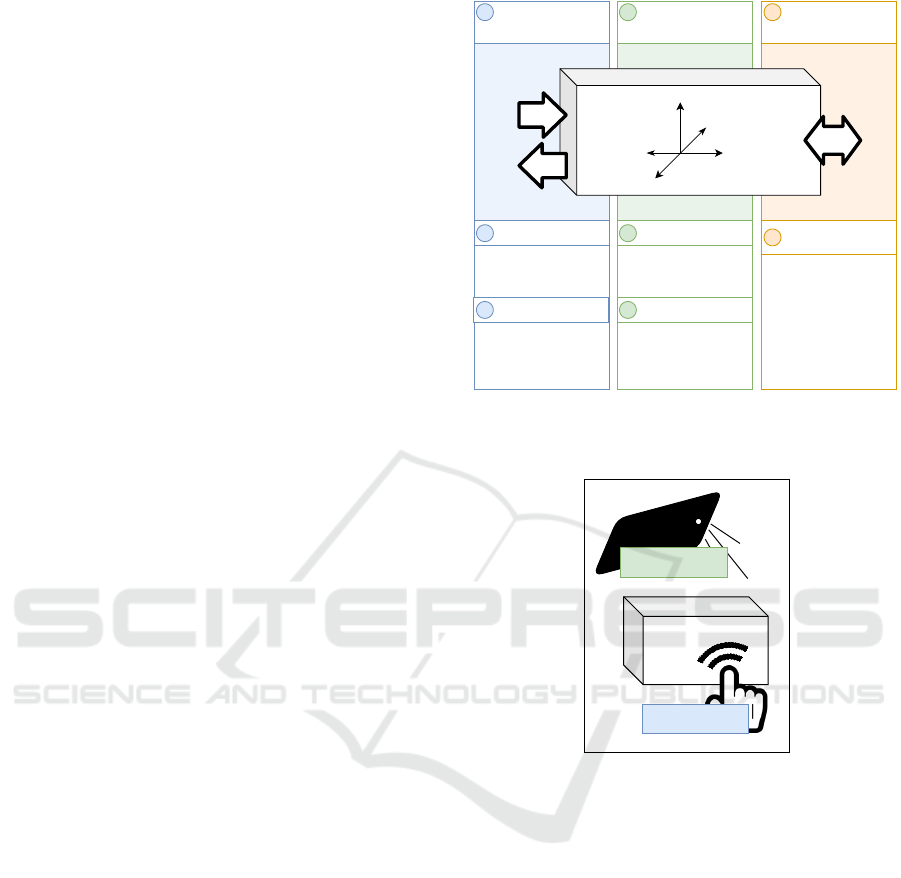
Conceptually, we identified three ways in which a tan-
gible object can be equipped with additional sensors
and control elements (see Figure 1). The first sec-
tion on the left corresponds to the area of a Human-
Machine-Interface (HMI). It describes two directions
of communication: (1) How does a user directly in-
teract with the tangible (HMI input), e.g., via buttons
or other control elements? (2) How can the tangi-
ble respond to the user (HMI output), for instance by
switching on an LED?
The second section is concerned with the tangible
object itself and its environment. In the following, we
will refer to sensors that analyze the object’s proper-
ties, such as a location or an orientation, as positional
sensors. For example, these can be accelerometers,
gyroscopes, or magnetometers. Other sensors gath-
Machine-Machine-
Interface (MMI)
Data Exchange/
Communication
3.1
- Bluetooth
- WiFi
- LAN
Object Properties
Environmental Sensors2.1
- Light Sensor
- Temperature Sensor
Human-Machine-
Interface (HMI)
HMI Input1.1
- Button
- Touch Sensor
-Rotary Angle Sensor
HMI Output1.2 Positional Sensors2.2
- LED
- Display
- Servo Motor
- Buzzer
- Gyroscope
- Accelerometer
- Magnetometer
Input
Output
1 2 3
Tangible Object
Figure 1: Categorization of sensors and control elements for
an immersive AR experience with an exemplary assignment
of sensors.
Direct Tangible
Interaction
Indirect Tangible
Interaction
Tangible
Object
Figure 2: Direct and indirect tangible interaction.
ering data from the tangible’s environment, such as
humidity, temperature, or brightness, are described as
environmental sensors. Figure 1 shows additional ex-
amples for each category. However, we do not claim
to present a complete overview of sensors. Still, the
classification of a sensor depends on the particular use
case. For instance, temperature differences can also
be triggered by human interaction. If that is intended
as HMI input, not as object property, the sensor would
be assigned to the first category.
Additionally, we distinguish the concepts of direct
and indirect interaction with the tangible object. Di-
rect tangible interaction occurs, e.g., when a button
was pressed directly on the tangible’s surface. Indi-
rect tangible interaction applies when another source
is needed to trigger an event, e.g., when the tangible is
rotated to switch between multiple application modes,
or a flashlight is used to influence the brightness val-
ues (see Figure 2).
Sensory Extension of a Tangible Object for Physical User Interactions in Augmented Reality
155

Finally, the third section (Figure 1 right) describes
the data exchange and communication with other ma-
chines (Machine-Machine-Interface, MMI). In addi-
tion to data exchange via wireless LAN and Blue-
tooth, sensors from the other two areas can also be
used. For example, the illumination of an LED of one
tangible object could cause a change in brightness of
the sensor of another one and thus trigger an action.
3.2 Functional Requirements
Once the appropriate sensors have been determined,
they need to be integrated into or attached to the tan-
gible object. We considered three aspects in this pro-
cess: The tangible’s structure, the power supply of
the electronics, and the communication with other de-
vices.
If the tangible object already exists, the selection
and the amount of possible sensors depends on the di-
mensions of the object. Since the electronics should
be hidden inside the tangible object to not alter the
outer appearance of the tangible, the interior must be
hollow and offer enough space for sensors, cables,
and control units such as a microcontroller. Besides
the measurements of the tangible object, the choice
of sensors depends on the object’s material and vice
versa. The material again influences the stability and
durability of the tangible.
Apart from hardware-sided requirements, the tan-
gible’s dimensions also affect the usability of the ap-
plication. Since the tangible needs to be moved freely,
it must not be too bulky or heavy. Depending on how
the virtual content is displayed, e.g., via HMD, mo-
bile device, or fixed screen, it must be considered
whether the user has to be able to move the tangi-
ble object with one hand or whether both hands are
available.
Since tangible object and sensors form a self-
contained unit, the power supply should be au-
tonomous. For example, microcontrollers can be sup-
plied by a small powerbank. However, it is important
to consider not only the external routing of the nec-
essary connections but also possible heat generation.
Besides, the power supply can have direct effects on
the functioning of other sensors such as magnetome-
ters.
4 IMPLEMENTATION
To illustrate our concepts, we developed a prototype
which uses a light sensor, a temperature sensor, ac-
celerometer data, and a touch sensor to enhance a 3D
printed skin model. In this use case, the skin model
Light Sensor
Temperature Sensor
Touch Sensor
Microcontroller
Accelerometer
Data exchange
via websocket
Tangible Object
Figure 3: Main application components and sensor place-
ment.
transports information about the structure and func-
tionality of human skin. The user can view details of
individual subcomponents and typical processes are
simulated. This way, medical knowledge from text-
books is made available interactively. We designed
the TAR application by selecting at least one sensor
from each category described in Section 3 and evalu-
ated how it can be used to display information about
the skin model.
Figure 3 shows the main components of the ap-
plication. The tangible object has sensors attached to
it and hides a microcontroller inside. The front end
application was developed in Unity, which supports
multiple platforms and thus provides the possibility to
view the virtual content on different devices. The ap-
plication setup has a modular structure, which makes
it easy to exchange sensors and representation frame-
works.
In the following, we will describe how we planned
to equip the skin model, considering which informa-
tion could be visualized later on. Based on this, we
set up the hardware including the 3D model of the
tangible object. Then we show how we connected the
sensors, transferred the data to the Unity application,
and conducted the processing.
HUCAPP 2021 - 5th International Conference on Human Computer Interaction Theory and Applications
156
4.1 Sensor Choice, Placement and
Hardware Setup
We chose suitable sensors for our use case based
on the classification proposed in Section 3 consider-
ing the tangible object to be used in medical educa-
tion. We started with the object properties and then
proceeded to the external communication with users
(HMI) and machines (MMI). Environmental sensors,
to start with, can be used to simulate external influ-
ences on the skin. For instance, the data of the tem-
perature sensor and a light sensor can help to visual-
ize sweat production, the aging process of the skin, or
the development of sunburn. Both sensors offer direct
as well as indirect interaction possibilities, e.g. the
light values can be decreased by covering the sensor
with the hand or increased using a flashlight. This is
directly available when using a mobile device with a
flashlight to display the virtual content. Since both
environment sensors visualize effects triggered by the
skin surface, we placed the sensors on top of the skin
model (see Figure 3). To render the virtual represen-
tation correctly, the current position and orientation
of the tangible object must be determined. In this
project, we focus on equipping the tangibles with sen-
sors. Therefore, we use an accelerometer as a posi-
tional sensor instead of visual tracking.
The virtual content, i.e. the HMI output, is to be
shown on a display. Since we mainly focused on how
to use the sensor data to enhance a tangible object,
any screen can be used to display the information.
We decided to use a tablet, as mobile devices offer
the advantage of already having integrated tools like
the flashlight mentioned above. Other elements for
displaying feedback such as LEDs or buzzers were
not used here as they have no natural equivalents in
the context of the skin model. For the HMI input, we
used a touch sensor enabling direct interaction with
the individual object parts. Finally, the sensor data
transferred to the front end application, i.e. to a sec-
ond machine by using a websocket interface the front
end client can connect to. For the prototypical imple-
mentation, we used the LAN module of the microcon-
troller.
The microcontroller is mounted together with the
powerbank on the base plate and aligned horizontally
to convert the accelerometer data correctly (see Fig-
ure 4). For development, we chose to use a FRDM-
K64F (NXP Semiconductors, 2016) microcontroller,
which is pin compatible with Grove sensors (Seeed
Technology Co., Ltd., 2020). Light and tempera-
ture sensors have been connected via two indepen-
dent analog-to-digital converter (ADC) ports. The
HMI input components, like buttons or touch sen-
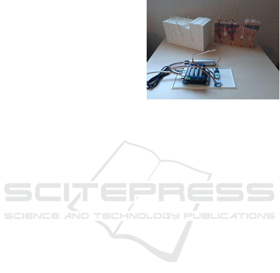
Figure 4: Previous model (right) and the newly printed skin
model (left), K64F with equipped sensors and connected
powerbank placed on the printed lid of the tangible object
(front).
sors, can be connected via the digital ports. The
on-board accelerometer can be accessed through the
Inter-Integrated Circuit (I
2
C) (NXP Semiconductors,
2014).
The 3D model’s dimensions are based on a col-
ored skin model and the development board sizes as
we did not build our own hardware in the scope of
this project. Figure 4 shows the hardware equipment
with the printed tangible object on the left and the col-
ored skin model on the right. Finally, the sensors are
mounted on the inside of the model. For the power
connection as well as for the LAN cable, appropriate
openings must be provided to bring the connections
to the outside.
4.2 Microcontroller and Data Retrieval
of the Sensors
For development on the microcontroller, we chose
to use FreeRTOS, an open-source real-time operat-
ing system for embedded systems. Compared to bare
metal solutions without an OS, it requires additional
computing and memory capacity, but allows a more
high-level view on the microcontroller and supports
multithreading. A separate thread can be used to man-
age each sensor leading to better code readability and
maintainability. The ability to easily switch between
different contexts compensates for the OS overhead
and helps to use resources efficiently. In the FreeR-
TOS context, the term task is used synonymously for
the term thread.
The application structure consists of one task for
each sensor and a web server task providing a web-
socket to forward the sensor data to the front end ap-
plication. All sensor tasks send their data to a queue,
Sensory Extension of a Tangible Object for Physical User Interactions in Augmented Reality
157

Figure 5: The front end application visualizing the trans-
ferred sensor data of the equipped skin model.
depending on their sample rate. The queue item con-
tains the data source, length, and a pointer to the ac-
tual data. Each queue item attribute is sent as a sep-
arate package within a superordinate frame contain-
ing the information of the connected client. The data
retrieval is regularly triggered by a periodic interrupt
timer (PIT) for all sensors except for the touch sen-
sor. Each task configures a PIT controller channel to
a different interrupt interval depending on the respec-
tive sensor. The accelerometer, for example, has the
shortest interval as motion data needs to be updated
most frequently.
4.3 Communication Protocol and
Virtual Representation
In order to display the information in the Unity appli-
cation the client is connected via websocket receiv-
ing the sensor data in byte arrays. The modular back
end structure is mirrored in the front end using a main
controller task to receive the data from the websocket
and individual controllers for each sensor. Currently,
the Unity application shows one label for each sensor
with the transmitted data and a skin model prefab, a
virtual representation of the tangible object, aligned
to the acceleration data (see Figure 5). In addition
to labels with raw data of each sensor, the values are
visualized.
As soon as the websocket connection is estab-
lished, the back end sends the data packets to the front
end. The websocket controller writes each incoming
message into the queue of the main controller, which
forwards it to the dedicated sensor controller. There
the package is decoded and the appropriate content is
displayed on the tablet screen.
A complete data sequence consists of three pack-
ages containing the data source, length, and the actual
data. The lengths of the packages form a byte pattern
which is stored by each sensor controller individually
and helps to check whether the sequence is complete
and assigned to the correct controller. In case the data
length of a packet does not correspond to the expected
package pattern, the current sequence is discarded. In
our application, all sequences start with one byte for
the source and four bytes for the data length. Only
the data length varies for each sensor. The byte pat-
tern defines a unique communication protocol, which
additionally allows to easily integrate further sensors
into the application.
After the main controller has delegated the tasks,
the individual sensor tasks can process the data inde-
pendently. The back end directly forwards the raw
data of the sensors to the front end. This way, the
server does not have to offer several conversion varia-
tions and exactly those conversions can be made that
are necessary for the virtual representation of the con-
tent.
The light and temperature sensor each send four
bytes with the current voltage value. The accelerom-
eter data consists of three values, one for each axis
of the coordinate system. The acceleration is mea-
sured by means of the local gravitational field. This
provides information on the accelerometer’s orienta-
tion which allows, e.g., mobile devices to automat-
ically switch between portrait and landscape. To
align the skin model prefab we calculated the rotation
around the respective coordinate system axis from the
transmitted values. In accordance with aircraft no-
tations, we use the following terms: yaw for z-axis
rotation, pitch for x-axis rotation, and roll for y-axis
rotation (NXP Semiconductors, 2017). Accelerome-
ters, however, only allow to determine roll and pitch.
Therefore, the tangible can only be tilted back and
forth as well as from left to right.
5 DISCUSSION AND LESSONS
LEARNED
To get an intention for the feasibility and the effort
compared to the benefit of integrating hardware com-
ponents in a TAR setup, we examined the individual
components of our approach and identified possible
weaknesses and optimization possibilities. The de-
sign of the concrete skin model enhancement in Sec-
tion 4.1 already showed that only four sensors enable
the representation of various virtual use cases. In this
section, we will discuss our findings and state lessons
learned from the implementation of the current sys-
tem.
At the beginning of this paper, we presented the
categorization we used to select the sensors. This
helped to define at least one sensor for each area of
the TAR setup and thus to define an immersive TAR
HUCAPP 2021 - 5th International Conference on Human Computer Interaction Theory and Applications
158

experience for use in medical education. The func-
tional requirements for the TAR setup are based on the
assumption to create a freely movable, transportable
TAR setup.
In the current implementation, the tangible is still
connected to the display device via LAN, but this can
easily be replaced by a WLAN module. However,
the 3D model’s dimensions should be adjusted more
specifically to the actual size of the sensors to en-
hance the user experience. During the development
process, the size was appropriate to be able to easily
make changes to the hardware. Still, the print thick-
ness needs to be reduced further, as it currently af-
fects the sensors’ efficiency. For instance, placing the
temperature sensor inside the model causes it to re-
act slower since the model’s material needs to warm
up first. So the 3D model’s structure needs to take
into account the characteristics of the sensors and be
durable enough to prevent protruding elements from
breaking off. Besides, openings for connections or
special requirements of individual sensors, such as en-
vironmental sensors, could already be provided in the
digital model for 3D printing.
Another optimization possibility is to use more
specialized hardware for both the sensors and the mi-
crocontroller. This reduces the tangible’s dimensions
and weight and has also an impact on the overall per-
formance and power consumption of the application.
The integration of further sensor information, like the
alignment of the magnetic field, could increase the
robustness of the tangible’s position determination.
When using only accelerometer data, the model can
wrongly be rotated by moving the tangible up and
down quickly.
Adding the sensors is determined by the hardware
layout, in our case the development board. Due to its
task-oriented structure, however, our application can
be extended flexibly to integrate further sensors and to
try different transmission priorities and sample rates.
Furthermore, the protocol used for the communica-
tion between the microcontroller and Unity applica-
tion is a convenient, simple solution to transfer the
data and interpret it correctly in the front end.
Still, the software on both sides is capable of fur-
ther optimization. On the back end side, the use of
PIT and ADC can be further optimized and a more
object-oriented approach can be tested to acceler-
ate the readout process of the sensors. Furthermore,
many of the functions currently implemented in the
software could be further accelerated by the proper
use of the hardware capabilities. For instance, the
Direct Memory Access (DMA) controller can per-
form memory operations without waking the proces-
sor. These optimizations can also reduce power con-
sumption. Overall, comparative performance mea-
surements should be conducted to get an indication
of the effectiveness of the optimizations.
On the front end side, the distribution of incoming
data packets could be parallelized by the sensor con-
trollers automatically taking the appropriate packets
from the entry queue. However, this requires to syn-
chronize the access to the queue and to consider the
occurrence of incomplete sequences. Still, this opti-
mistic method increases the application performance,
in case the probability of incomplete packets is rel-
atively low. When introducing more restrictive syn-
chronization mechanisms, the additional administra-
tive effort needs to be included in the performance
measurement. The effort is further increased by the
fact that Unity functions such as the assignment of
object attributes are not thread-safe.
Additionally, the sending rate of the back end has
an impact on the optimization capabilities of the front
end. If its update rate exceeds the processing in the
front end, outdated data needs to be discarded to avoid
the calculation of negligible values. However, the
reception time of the respective package would also
have to be managed for this.
Further optimizations could be made in the pro-
cessing of the raw data and its virtual representation.
To compensate for measurement inaccuracies, for ex-
ample, an interpolation of the values between the in-
dividual frames could be incorporated. Overall, we
can state many lessons learned from our approach for
the integration of hardware and the use of sensors in
a TAR setup.
6 CONCLUSION AND FUTURE
WORK
In this paper, we investigated the extension of tangible
objects with the help of sensors to provide TAR-based
interactions. We assigned sensors and control ele-
ments to three main categories and formulated func-
tional requirements for the tangible object. We devel-
oped a prototype choosing sensors based on our cat-
egorization and equipped the prototype with a light
sensor, a temperature sensor, an accelerometer, and
a touch sensor to enhance a 3D printed skin model.
The application was built modular to allow easy ex-
tension by additional sensors. By describing techni-
cal details of the implementation, we gave practical
advice on how to design and implement TAR setups.
We also pointed out the limitations of the current im-
plementation and listed hardware and application side
optimization possibilities. These show the flexibility
of the modular application structure and the potential
Sensory Extension of a Tangible Object for Physical User Interactions in Augmented Reality
159

for further add-ons.
In the future, more complex scenarios, feedback
mechanisms, and the usefulness of the same sensors
for displaying different content will be investigated.
The sensor equipment can also be combined with
other tracking and interface methods such as optical
tracking or verbal commands. In case of a sensor
fusion with optical tracking, the inclusion of sensors
may compensate for shortcomings like tangibles with
only few features. At last, we will conduct a user
study to investigate the impact of tangible’s size and
weight on usability.
ACKNOWLEDGMENTS
This project (HA project no. 690/19-10) is financed
with funds of LOEWE – Landes-Offensive zur
Entwicklung Wissenschaftlich-
¨
okonomischer Exzel-
lenz, F
¨
orderlinie 3: KMU-Verbundvorhaben (State
Offensive for the Development of Scientific and Eco-
nomic Excellence).
REFERENCES
Bier, E. A., Stone, M. C., Pier, K., Buxton, W., and DeRose,
T. D. (1993). Toolglass and magic lenses: the see-
through interface. In Proceedings of the 20th con-
ference on Computer graphics and interactive tech-
niques, pages 73–80.
Billinghurst, M., Kato, H., and Poupyrev, I. (2008). Tangi-
ble augmented reality. ACM SIGGRAPH ASIA 2008
Courses.
D
¨
oring, D. C., Horst, R., Rau, L., and D
¨
orner, R. (2020).
Interface techniques for tangible augmented reality in
a mobile device setup for magic lens experiences. In
Weyers, B., L
¨
urig, C., and Zielasko, D., editors, GI
VR / AR Workshop. Gesellschaft f
¨
ur Informatik e.V.
Funk, M., Korn, O., and Schmidt, A. (2014). An augmented
workplace for enabling user-defined tangibles. In CHI
’14 Extended Abstracts on Human Factors in Com-
puting Systems, CHI EA ’14, page 1285–1290, New
York, NY, USA. Association for Computing Machin-
ery.
G
¨
unther, S., M
¨
uller, F., Schmitz, M., Riemann, J., Dez-
fuli, N., Funk, M., Sch
¨
on, D., and M
¨
uhlh
¨
auser, M.
(2018). Checkmate: Exploring a tangible augmented
reality interface for remote interaction. In Extended
Abstracts of the 2018 CHI Conference on Human Fac-
tors in Computing Systems, CHI EA ’18, page 1–6,
New York, NY, USA. Association for Computing Ma-
chinery.
Huber, J., Steimle, J., Liao, C., Liu, Q., and M
¨
uhlh
¨
auser,
M. (2012). Lightbeam: Interacting with augmented
real-world objects in pico projections. In Proceedings
of the 11th International Conference on Mobile and
Ubiquitous Multimedia, MUM ’12, New York, NY,
USA. Association for Computing Machinery.
Ishii, H. and Ullmer, B. (1997). Tangible bits: Towards
seamless interfaces between people, bits and atoms.
In Proceedings of the ACM SIGCHI Conference on
Human Factors in Computing Systems, CHI ’97, page
234–241, New York, NY, USA. Association for Com-
puting Machinery.
Kaltenbrunner, M. and Bencina, R. (2007). reactivision:
a computer-vision framework for table-based tangible
interaction. In TEI’07: First International Conference
on Tangible and Embedded Interaction.
Kaltenbrunner, M., Bovermann, T., Bencina, R., Costanza,
E., et al. (2005). Tuio: A protocol for table-top tangi-
ble user interfaces. In Proceedings of the 6th Interna-
tional Workshop on Gesture in Human-Computer In-
teraction and Simulation, pages 1–5.
Kaltenbrunner, M. and Echtler, F. (2018). The tuio 2.0 pro-
tocol: An abstraction framework for tangible inter-
active surfaces. Proc. ACM Hum.-Comput. Interact.,
2(EICS).
Lee, W. and Park, J. (2005). Augmented foam: A tangi-
ble augmented reality for product design. In Fourth
IEEE and ACM International Symposium on Mixed
and Augmented Reality (ISMAR’05), pages 106–109.
IEEE.
NXP Semiconductors (2014). I2C-bus specification and
user manual. Rev. 6.
NXP Semiconductors (2016). Kinetis K64F Sub-Family
Data Sheet. Rev. 7.
NXP Semiconductors (2017). 6-axis sensor with integrated
linear accelerometer and magnetometer. Rev. 8.
Seeed Technology Co., Ltd. (2020). Grove sen-
sors. https://www.seeedstudio.com/category/Sensor-
for-Grove-c-24.html. Accessed: 2020-10-02.
Watanabe, R., Itoh, Y., Asai, M., Kitamura, Y., Kishino, F.,
and Kikuchi, H. (2004). The soul of activecube: Im-
plementing a flexible, multimodal, three-dimensional
spatial tangible interface. In Proceedings of the 2004
ACM SIGCHI International Conference on Advances
in Computer Entertainment Technology, ACE ’04,
page 173–180, New York, NY, USA. Association for
Computing Machinery.
Zatulovsky, D. and El-Sana, J. (2019). Tangible stickers: A
sensor based tangible user interface. In International
Conference on Virtual Reality and Augmented Reality,
pages 297–304. Springer.
HUCAPP 2021 - 5th International Conference on Human Computer Interaction Theory and Applications
160
