
Hexahedral Mesh Generation for Tubular Shapes using Skeletons and
Connection Surfaces
P. Viville, P. Kraemer and D. Bechmann
ICube, Université de Strasbourg, CNRS, France
Keywords:
Mesh Generation, Skeleton, Hexahedral Meshing.
Abstract:
We propose a pipeline for the generation of hexahedral meshes for domains whose shape can be properly
represented by their 1-dimensional skeleton. By leveraging this representation, the resulting mesh is aligned
with the geometry of the domain and its connectivity is as regular as possible. The main challenge lies in
the management of the connectivity around branching points that can have an arbitrary number of incident
branches. We propose a new solution with the construction of connection surfaces that encode the connectivity
of the final volume mesh around each vertex of the skeleton. Each vertex is processed independently in a
mutually compatible way, thus sparing the resolution of a global constraint problem. This leads to a pipeline
that does not need particular handling in the presence of cycles and in which most steps are able to process the
cells in a parallel way.
1 INTRODUCTION
The construction of a volume mesh from the surface
of a geometric domain has been a widespread sub-
ject of research for several decades. Most methods
attempt to solve this problem for domains of arbitrary
geometries. However, depending on the purposes we
define for our meshes, these generic methods might
provide unsatisfactory results. Concerning the shape
of cells, some methods generate cells of lower qual-
ity, in particular near the boundaries of the domain,
which is generally an area of greater importance. As
for the nature of cells, a few methods generate only
tetrahedrons whereas others cannot guarantee the pu-
rity of the results and produce mixed meshes which,
depending on context, might not fulfill the require-
ments. Purely hexahedral meshes are still notoriously
difficult to build even though they are necessary or at
least highly appreciated for many applications.
Specialized methods can be proposed for the par-
ticular case of tubular objects, i.e. shapes whose cross
section with respect to their 1-dimensional skeleton is
roughly circular. The goal then is to create meshes
whose quality and regularity are higher than those
produced by generic methods, by taking advantage of
the intermediate skeletal representation whilst offer-
ing a simpler and more efficient implementation.
The whole process chain includes the extraction of
a skeleton, the re-sampling of the skeleton, the gener-
ation of the volume mesh initial connectivity, refine-
ment and adaptation to the geometric domain, as well
as the optimization of the shape of the cells. One of
the main challenges in this process is the handling
of the connectivity of the mesh around the branch-
ing points of the skeleton. This is where our main
contribution lies. We propose a technique that can be
applied on a branching point of any degree. Depend-
ing on the local configurations, a few variations can
also be applied. Because these different techniques
are all mutually compatible and each local choice has
no effect on the remainder of the object, many types
of skeletons can be directly managed even in the pres-
ence of cycles, and cells can be processed in a parallel
way through our devised algorithm.
2 EXISTING METHODS
Several general purpose hex-meshing methods have
been proposed. They are based on different ap-
proaches such as grid based (Schneiders, 1996),
volumetric parametrizations (Nieser et al., 2011),
(Livesu et al., 2013), advancing fronts (Kremer et al.,
2014), centroidal voronoi tessellations (Lévy and Liu,
2010), frame fields generation (Kowalski et al., 2016),
(Sokolov et al., 2016) and block decomposition, ei-
ther with manual input (Lu et al., 2017) or automat-
ically guided by a surface cross field (Livesu et al.,
2020). These methods are well proven, foresight con-
Viville, P., Kraemer, P. and Bechmann, D.
Hexahedral Mesh Generation for Tubular Shapes using Skeletons and Connection Surfaces.
DOI: 10.5220/0010222000450054
In Proceedings of the 16th International Joint Conference on Computer Vision, Imaging and Computer Graphics Theory and Applications (VISIGRAPP 2021) - Volume 1: GRAPP, pages
45-54
ISBN: 978-989-758-488-6
Copyright
c
2021 by SCITEPRESS – Science and Technology Publications, Lda. All rights reserved
45

cerning the nature, shape, or alignment, of the cells is
often limited. The issues are compounded in the case
of purely hexahedral meshing which can be a require-
ment of computation tools we might want to apply to
the mesh.
A few methods, building either surface or volume
meshes, have been developed to handle the special
case of skeletonizable tubular shapes.
(Hijazi et al., 2010) constructed an hybrid trian-
gle/quad surface mesh around a given skeleton. The
branches are thickened as triangular prisms. On each
branch point, the convex hull of the projection on a
sphere of the incident branches triangular section is
constructed. Branches are finally connected to these
intersection meshes to form the final mesh.
(Livesu et al., 2016) offered an extension of the
quadrilateral surface mesh generation described in
(Usai et al., 2015) to produce hexahedral meshes. A
hexahedron is placed on each vertex of the skeleton
with a degree higher than 2. It is then oriented and
subdivided according to incoming branches before
being extruded along the skeleton branches. In spite
of good results, this method suffers from significant
issues. The cuts created on the branching point hex-
ahedra have to be mutually compatible, and a global
optimization problem has to be solved. Such a solu-
tion does not always exist, thus leading to some ar-
bitrary choices of connectivity, particularly when the
skeleton contains cycles. The propagation of the cuts
along the skeleton branches during extrusion also cre-
ates extraneous hexahedra in the initial crude mesh.
Finally, depending on the degree and angles of the
incident branches, the cube fitting approach do not al-
ways lead to the most symmetric or natural results.
(Panotopoulou et al., 2018) and (Fuentes Suárez
and Hubert, 2018) presented a method to generate a
minimal quadrilateral surface mesh around a skele-
ton. On each branching point, a sphere is partitioned
into as many faces as incident branches. To sleeve the
branches with exclusively quadrilateral faces without
inserting irregular vertices, the sphere faces on ei-
ther side of a branch have to expose identical degrees.
Several steps in the method we propose are inspired
from these methods that target surface meshes.
(Verhetsel et al., 2019) offered a method to build a
hexahedral mesh contained inside a sphere partitioned
into quads. Even though this work could be of partic-
ular interest for our process, its scope is fairly limited
and we have developed a solution that is considerably
simpler and faster.
3 PROPOSED METHOD
This section describes our hex-meshing method. We
first give a general description of the algorithm, with
generic handling of the branching points in mind.
Branching points processing and their compatible
specializations will then be explained in more detail.
Terminology In the skeleton graph, we call extrem-
ity a vertex of degree 1, joint a vertex of degree 2, and
branching point a vertex of higher degree. Extrem-
ities and branching points are the ends of branches
along which only joints can be found. We call a chunk
the set of hexahedra associated to each edge of the
skeleton.
3.1 Process Overview
Connection Surfaces. First, a connection surface is
created for each vertex of the skeleton. The connec-
tivity of those surfaces will contain the information
required to connect the hexahedral cells that are gen-
erated on each edge along the branches of the skele-
ton, serving as a scaffold for the geometry and con-
nectivity of the final mesh.
For each vertex, a partition of a sphere in a quadri-
lateral surface mesh is created with as many faces as
branches incident to the skeleton vertex. Regardless
of the number of branches incident to the vertex – and
therefore quads in the partition – such a connectivity
can always be found.
Indeed, according to Euler’s formula for surfaces
of genus 0 we have v − e + f = 2, with v the number
of vertices, e the number of edges, and f the number
of faces. f being set and the number of edges per face
being 4, we get e = 2 f and v = 2 f − f + 2 = f + 2
which has an integer solution for any value of f .
Requiring the sphere partition to present only
quadrilateral faces will allow us at a later stage to gen-
erate a first hexahedral mesh that exhibits no irregular
vertices along the branches.
Figure 1: Quad partitions of a sphere around vertices of
degree 1, 2, and 4.
For joints, this step is trivial, a dihedron composed
of 2 quads can be inserted onto the vertex (Figure 1 b).
For extremities, the same dihedron can be used while
GRAPP 2021 - 16th International Conference on Computer Graphics Theory and Applications
46
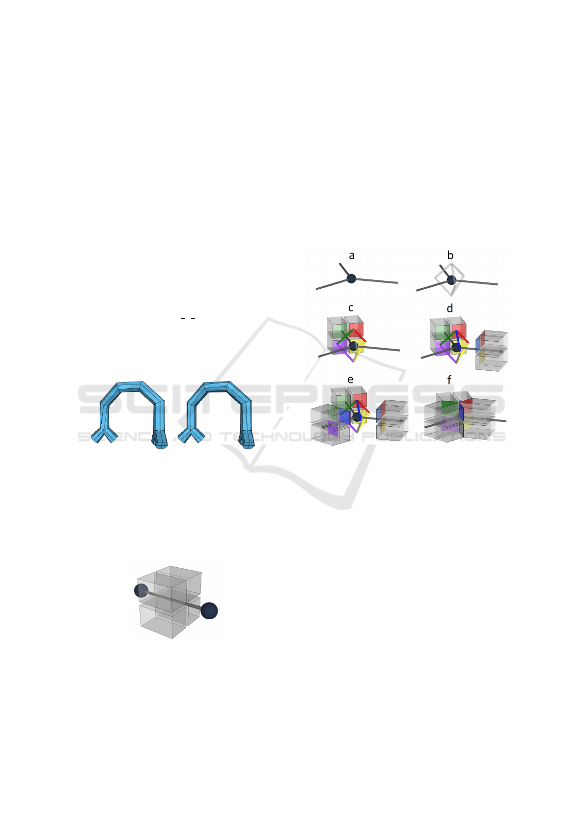
simply treating one of the quads as boundary (Figure
1 a). The algorithm used to partition the sphere for
higher degree branching points (Figure 1 c: example
of degree 4) is detailed in the following section.
Geometry. For joints and extremities, the vertices
are set on the plane orthogonal to the tangent of the
skeleton at that vertex. Rotation around that tangent
axis remains as a degree of freedom. For branching
points, the position of the vertices on the sphere are
constrained by the partitioning process and can thus
be used as a basis to set the rest of the geometry.
An initial frame is computed for each quad of the
branching point connection surfaces. These frames
are then propagated along branches using a rotation
minimizing frame scheme (Wang et al., 2008). If a
branch has branching points at both ends, the angle
formed between the frame propagated from one end
and the frame computed on the other end is computed.
This angle, bounded by [−
π
4
,
π
4
], is then back propa-
gated along the branch using an arc length parameter-
ization (Figure 2). For every joint along the branch
and on extremities, the propagated frames enable us
to set the geometry.
Figure 2: Twist redistribution between two branching
points.
Hexahedra Generation. For each edge of the
skeleton graph, a set of four hexahedra – a chunk –
is generated and linked to the edge. Both sides of the
chunk exhibit an interface composed of 4 quads (Fig-
ure 3).
Figure 3: Hexahedra chunk around an edge of the skeleton.
Each edge of the skeleton is incident to two ver-
tices. During the first step a connection surface is built
for each vertex of the skeleton. Each incident branch
of the vertex is associated to a quad of this surface
(Figure 4b). The four front-facing quads of the cor-
responding chunk are paired with the four edges of
the connection surface quad (Figure 4c and d). By the
end, whatever the degree of the branching point, each
edge of the connection surface is paired with exactly
two hexahedra (Figure 4e). To complete the connec-
tivity of the hexahedral mesh, those pairs of hexahe-
dra are connected together through the face they re-
spectively exhibit to the connection surface edge (Fig-
ure 4f). This process demonstrated on a vertex of de-
gree 3 in Figure 4 can be generalized to vertices of
any degree as long as a proper quad connection sur-
face has been built.
Figure 4: The connection surface built on each skeleton ver-
tex is used as a scaffold for the geometry and connectivity
of the hexahedra. (a) a vertex incident to three branches
(b) the connection surface composed of three quads (c,d,e)
incident chunks are paired (indicated by colour) with their
associated quad edges (f) pairs of hexahedra are connected.
3.2 Branching Points Processing
As stated in the previous section, to handle complex
branching points of degree higher than 2, we strive to
construct the partition of a sphere into a given number
of quads each containing an entry point correspond-
ing to the direction of one of the incident branches
on the sphere. The positions of these entry points are
fixed and cannot be modified.
The fact that a sphere can be partitioned into any
number of quads implies that there exists a dual mesh
of this partition in which all vertices are of degree 4.
Our first goal is then to create a mesh whose vertices
are the entry points and are all of degree 4. The dual
of that mesh will be the quadrilateral partition of a
sphere that we are looking for, with each face con-
Hexahedral Mesh Generation for Tubular Shapes using Skeletons and Connection Surfaces
47
taining its entry point.
Initially, we compute the convex hull of the entry
points. Since the points are on a sphere this convex
hull corresponds to the Delaunay triangulation of the
set of points (Na et al., 2002). In a second step, we
update the connectivity of this triangulation to set all
degrees to 4.
This remeshing is performed in two stages. First,
a degree reduction stage for all vertices of degree
higher than 4, followed by a degree increasing stage
for all pairs of vertices of degree 3. If we do not cre-
ate any vertex of degree lower than 3 during the first
stage we are certain that there will be 0 or an even
number of vertices of degree 3. This can be shown
again with Euler’s formula, here applied to the primal
mesh. If we have f = q + t with q number of quads
and t the number of triangles, then e =
3
2
t + 2q and
v =
1
2
t + q + 2 which only has integer solutions for
an even number of triangles. Therefore the dual mesh
has an even number of vertices of degree 3 which can
be eliminated by pairs by using a method derived from
(Peng et al., 2011).
We aim to minimize the number of remeshing op-
erations in order for the result to be as close to the
Voronoï diagram of the entry points as possible. This
will also help to preserve the convexity of the spheri-
cal quads and the inclusion of the entry points in their
respective face of the partition. Since the number of
vertices and their positions cannot be modified, the
only operations at our disposal are adding an edge (or
cutting a face) and deleting an edge (or merging two
faces).
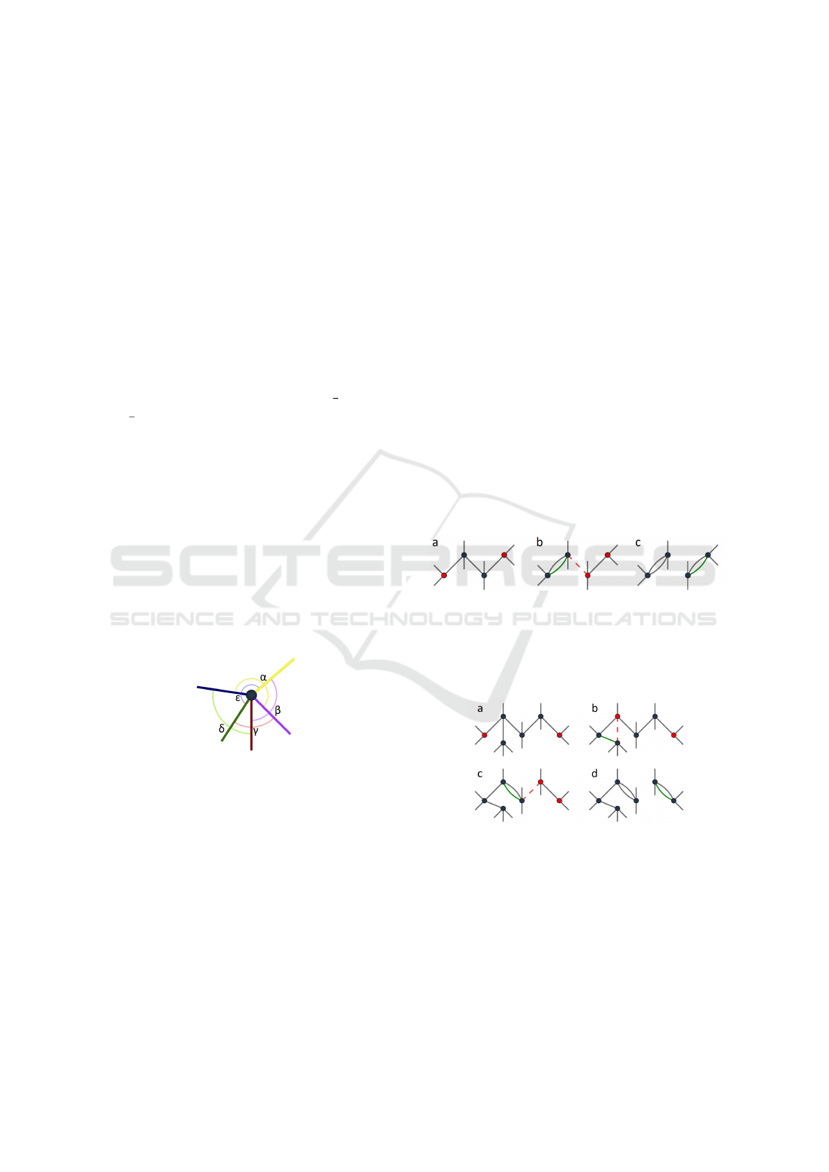
Figure 5: Angle criterion: γ < β < δ < ε < α.
Our main criterion for prioritizing the remesh-
ing operations is the angle between edges incident
to a vertex. The heuristic will carry out the opera-
tions in order to minimize angles created when delet-
ing edges (Figure 5) and to maximize angles created
when adding edges. Focusing on angles seemed to be
the most relevant criterion to minimize the degree of
the polygons created in the final mesh and maximize
their convexity.
We propose the following algorithm:
Degree Reduction Stage:
• Deletion of edges incident to two vertices of de-
gree higher than 4, ordered by the smallest created
angles.
• Deletion of edges incident to a vertex of degree
higher than 4 and a vertex of degree 4, ordered by
the smallest created angles.
Removal of 3 - 3 Pairs
• Add an edge between two non-adjacent vertices
of degree 3 of a face.
• Add an edge between two adjacent vertices of de-
gree 3 of a face.
• Search all the shortest paths between pairs of ver-
tices of degree 3, sorted by descending length. A
set of operations is then applied depending on the
parity of the path length. For paths of odd lengths
(Figure 6): by adding an edge and deleting the
next one, the vertex of degree 3 is moved along
the path by 2 steps. Once both vertices of degree
3 are adjacent, their degrees are increased to 4 by
adding an edge between them. For paths of even
lengths (Figure 7): by using a vertex adjacent to
the path the vertex of degree 3 is shifted by one
step along the path and the scheme used for odd
length paths can be applied.
Figure 6: Connectivity modification between two vertices
of degree 3 (in red) separated by an odd length path (a).
Doubling an edge and deleting the next one moves a degree
3 vertex of two steps along the path (b). Once the degree 3
vertices are adjacent, a last edge increases both their degree
to 4 (c).
Figure 7: Connectivity modification between two vertices
of degree 3 (in red) separated by an even length path (a).
An adjacent vertex is used to shift a degree 3 vertex by one
step along the path (b). Then we are left with the odd length
case (c-d).
Once this mesh is only composed of vertices of
degree 4, we compute its dual to obtain the desired
quad mesh. Vertices of the quad mesh are placed at
the barycenters of the faces. As a final result we ob-
tain a sphere partitioned in quadrilaterals with an en-
try point associated to each face. Figure 8 shows the
GRAPP 2021 - 16th International Conference on Computer Graphics Theory and Applications
48
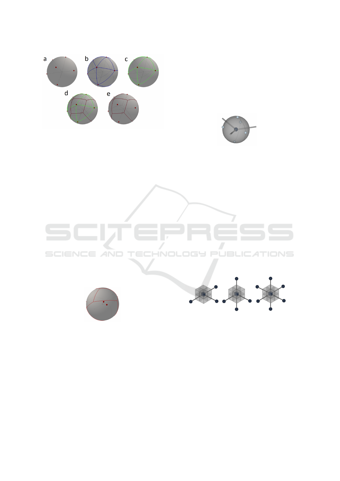
Figure 8: Quad partitioning algorithm on a sphere. Given
an initial set of points, we obtain a quad mesh where each
quad contains one of the given points. (a) Intersection of the
branches with a sphere (b) Construction of the Delaunay tri-
angulation (c) Remeshing of the triangulation (d) Construc-
tion of the dual mesh (e) Resulting quad mesh connection
surface.
different steps of the algorithm on an example of de-
gree 7.
This algorithm yields good results – i.e. a parti-
tion of the sphere with convex quads each contain-
ing one entry point – in most of the cases encoun-
tered when working on skeletons extracted from usual
shapes. Some challenging, mostly artificial, branch-
ing points geometries can prove to be problematic and
do not allow us to obtain such a partition. Figure 9
shows a configuration that results in a partition where
some points are out of their quad. These irregularities
can be mostly corrected in the following geometry op-
timization step but the resulting mesh is likely to be
of lower quality. However, improvements can still be
made to obtain better results in the most challenging
configurations.
Figure 9: A failure example of the quad partitioning of the
sphere: not all quads contain their respective point.
3.3 Special Cases
In addition to the generic algorithm presented in the
previous section, we chose to distinguish two cases
in which a specialized, yet globally compatible, al-
ternative can be used to generate the connectivity of
the branching points. When their required conditions
are fulfilled, these specializations are applied in prior-
ity and allow the generation of an initial coarse mesh
with higher quality elements.
Flat Cases. For flat branching points where all en-
try points are on or near a common plane, an "orange
slice" type connectivity is generated. This is inspired
by the initial step of the sphere partition method of
(Panotopoulou et al., 2018). For such a point with n
branches, we create a connection surface quad mesh
composed of two vertices of degree n, the poles, and n
vertices of degree 2 along the meridians (Figure 10).
Figure 10: "Orange slice" handling of a flat branching point
of degree 3.
Cube Cases. For branching points whose degree is
between 3 and 6, and for incident branches direc-
tions that are either mutually orthogonal or pairwise
aligned, a subdivided cube is inserted (Figure 11). As
in (Usai et al., 2015), a cube is fitted at the branching
point location, keeping the incident branches direc-
tion as orthogonal as possible to the cube faces. If a
face of the fitted cube is pierced more than once, or an
angle between a branch and the corresponding cube
face normal exceeds a chosen threshold, this special-
ization is discarded and we revert to one of the pre-
vious methods. The subdivided cube exposes a com-
patible interface for the connection with the incoming
branches chunks, allowing this special case to be in-
tegrated seamlessly in the overall process.
Figure 11: Examples of orthogonal intersections.
Figure 12 illustrates two different configurations
of a degree 3 vertex. In the first one (a) the three
branches form 120
◦
angles. Using a sphere partition
(left) generates better shaped elements than fitting a
cube (right). In the second one (b) the branches form
a T shape. In this case, fitting a cube (right) yields
better shaped elements. The versatility of our method
allows it to use the best method on each skeleton ver-
tex depending on the local configuration.
Hexahedral Mesh Generation for Tubular Shapes using Skeletons and Connection Surfaces
49
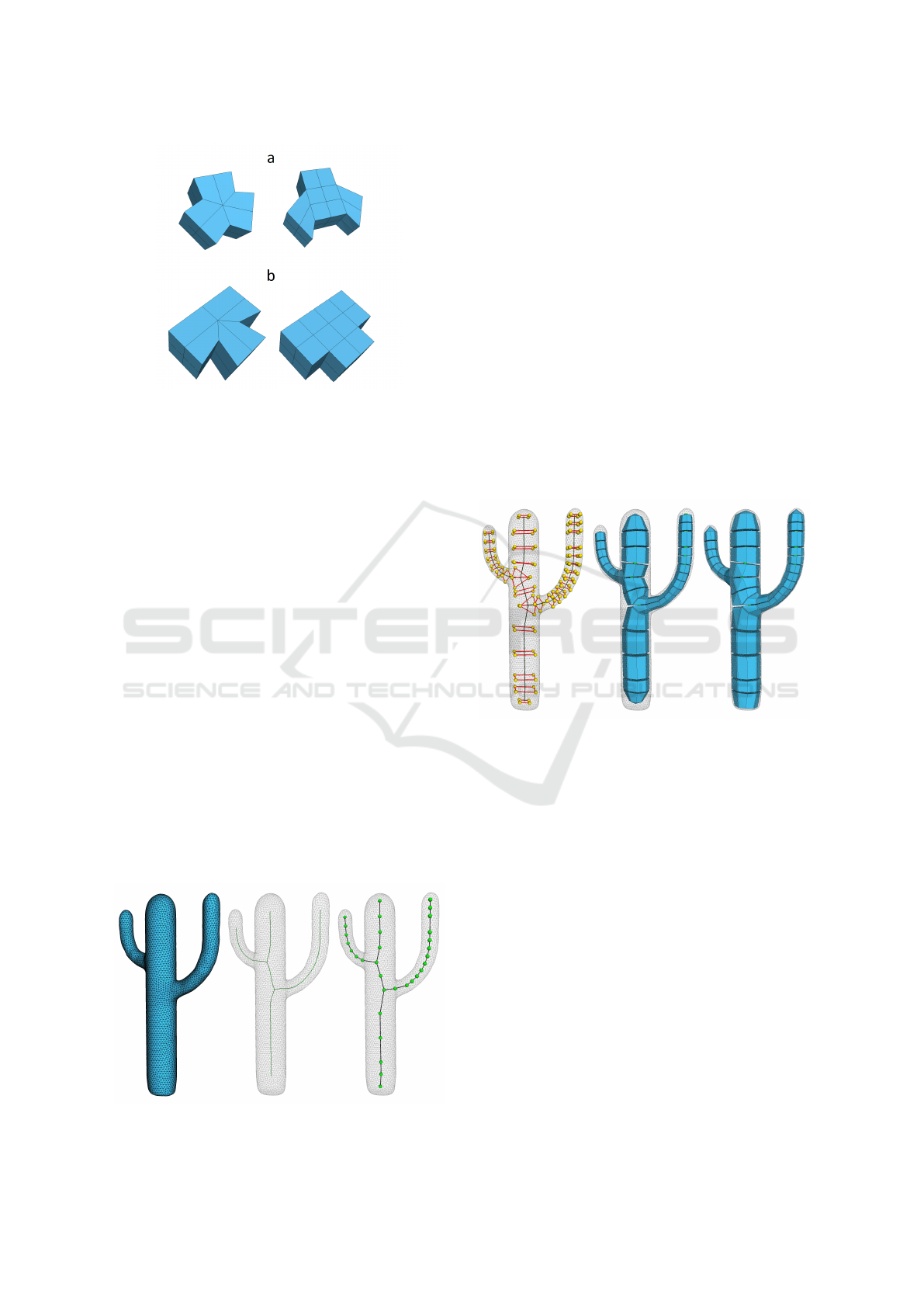
Figure 12: Comparison of sphere partitioning and cube
insertion technique on two degree 3 vertices. Minimum
scaled Jacobian: a) 0.802 (left) 0.409 (right); b) 0.533 (left)
1 (right).
4 MESH GENERATION PIPELINE
We present here the whole process we have devel-
oped, illustrated with a simple example.
4.1 Skeleton Extraction
The entry point of the hexahedral mesh generation
algorithm is a 1-dimensional skeleton with a posi-
tion and a radius on each vertex. This skeleton can
be given, or extracted from an input surface using a
method such as Mean Curvature Flow (Tagliasacchi
et al., 2012). In this case, the skeleton is subsequently
resampled (Figure 13) in order for edge lengths to be
related to the local shape radius. This allows elements
of the generated coarse mesh to be as regular as pos-
sible. However, if desired, anisotropic elements can
easily be obtained by changing the parameter that ties
the subdivision of the skeleton to the local shape ra-
dius. When the enclosing surface geometry is com-
plex, the quality of the skeleton and its ability to cap-
Figure 13: Extraction and resampling of the skeleton.
ture the features of the shape will strongly impact the
quality of the resulting hexahedral mesh. Of course,
the skeleton can also be manually processed if the ap-
propriate tools and required time are available.
4.2 Initial Mesh Generation
The connection surfaces are built independently on
each vertex of the skeleton (Figure 14 left). The ge-
ometry is set, then propagated from the branching
points to the joints and extremities. A rough hexahe-
dral mesh is generated by creating the chunks for each
skeleton edge and connecting them following the con-
nection surfaces (Figure 14 middle). The vertices are
then projected along their normals onto the enclosing
surface, if any (Figure 14 right). This projection step
can cause potential issues with self intersections that
can be solved using mapping methods such as the one
described by (Komaritzan and Botsch, 2018).
Figure 14: Generation of the connection surfaces and rough
volume mesh.
The locality of each step allows the following
steps to process the cells in parallel: generation of
connection surfaces for each skeleton vertex; gener-
ation of hexahedral chunks for each skeleton edge;
gluing of the hexahedral elements for each connec-
tion surfaces edge; projection of the vertices on the
surface.
4.3 Refinement and Geometry
Optimization
The resulting mesh depends on the sampling of the
skeleton and is as rough as our algorithm can produce.
In order to get a better and usable resulting mesh, the
mesh will have to go through several steps of process-
ing and optimization.
Subdivision and Padding. A global primal subdi-
vision step, or local subdivisions like cutting chunks
GRAPP 2021 - 16th International Conference on Computer Graphics Theory and Applications
50
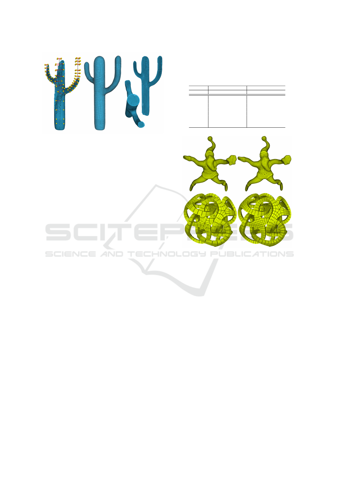
Figure 15: Refinement and geometry optimization.
along a given branch, can be executed to refine the
mesh and allow better fitting to a detailed surface.
Hexahedra that expose more than one face to the
boundary of the mesh can lead to badly shaped ele-
ments when constrained to an enclosing surface. A
classical way of dealing with this issue is to add a
padding layer to the whole surface of the mesh. Each
element of the mesh then has at most four vertices on
the boundary leaving more freedom to the subsequent
geometry optimization process.
Geometry Optimization. Considerable studies on
geometric optimization of hexahedral meshes has al-
ready been carried out (Livesu et al., 2015), (Gao and
Chen, 2016). The goal is usually to modify the posi-
tion of the vertices to increase the quality of the hex-
ahedra by fitting their shape closer to that of a rectan-
gular cuboid, while preserving the outer surface ge-
ometry. Several quality measures exist (Gao et al.,
2017), the most prevalent one being the scaled Jaco-
bian, computed for each element of the mesh. A neg-
ative value indicates an inverted element – which can
make a whole mesh unusable for physical simulation
– and rectangular cuboids have a value of 1. The worst
and the average value over the whole mesh are usually
highlighted as good indicators of the global quality
of a model. In our experiments, we used the edge-
cone rectification approach described in (Livesu et al.,
2015) whose iterative process improves the quality of
the elements and converges to an inversion-free mesh.
5 RESULTS
Figure 18 shows some hexahedral meshes obtained
with our method. Number of cells, minimum and av-
erage scaled Jacobian of the hexahedra of these mod-
els are presented in Table 1.
Compared to previous methods such as (Livesu
et al., 2016) and (Livesu et al., 2020) the quality of
Table 1: Minimum and average scaled Jacobian of the gen-
erated meshes presented in Figure 18. Values reported in
the previous works come from (Livesu et al., 2016) for
the Dinopet, Cactus, Fertility and Santa models and from
(Livesu et al., 2020) for the Metatron model.
Previous works Ours
Model Min/Avg SJ #Hex Min/Avg SJ #Hex
Dinopet .177/.920 18080 .540/.919 13120
Horse .449/.912 5568
Cactus .526/.919 4128 .635/.930 2400
Fertility .500/.892 7456 .543/.933 6848
Cycles .316/.937 8192
Vessel .615/.930 24592
Santa .367/.941 26240 .514/.965 21312
Metatron .682/.941 4544 .820/.981 6624
Figure 16: On the left, results obtained by (Livesu et al.,
2016) (Santa) and (Livesu et al., 2020) (Metatron), on the
right, our results. Combining cube fitting and sphere parti-
tioning techniques depending on the angles in the branch-
ing points improves the symmetry and the overall elements
quality of the obtained hexahedral meshes.
the constructed meshes is generally higher while be-
ing composed of fewer elements. Average quality
could be improved further by applying some of the
described subdivision techniques. However, our main
point here is not on purely numerical quality results.
What we emphasize is the ability of our method to
process each skeleton branching point individually.
Branching points in which a cube does not naturally
fit are processed with the more general sphere quad
partition approach. This allows complex branching
points to be handled without propagating additional
cuts and constraints along the incident branches (such
as in the Cycles model for which the central connec-
tion surface is depicted on its right).
More symmetric results are also obtained, such as
in the Santa model in which the torso branching point
is handled with a cube while the hips branching point
is handled with a sphere partition (Figure 16). A com-
bination of cube and sphere partition techniques is
Hexahedral Mesh Generation for Tubular Shapes using Skeletons and Connection Surfaces
51

also used in the Metatron model, here compared side-
by-side with the result obtained with the more gen-
eral method presented in (Livesu et al., 2020). The
regularity of the result is improved by using the most
suitable connection surface depending on the angles
in the branching points.
The pipeline is yet to be made fully automatic and
the different steps are triggered manually, therefore
giving exact figures of execution times is not possible.
Resampling of the skeleton, generation of the con-
nection surfaces and generation of the rough hexahe-
dral mesh are all near immediate, even with the larger
models we have used. This efficiency is mainly due to
the fact that the algorithm processes each branching
point independently and, unlike most existing meth-
ods, does not have to set up and resolve any global
constraints problem. Time spent in the fitting to the
surface and iterative geometry optimization steps is
dependent on the requirements of the final user. In the
examples used in 18, the optimization time ranged in
the order of a few seconds in total. In comparison, the
estimated times range from 1.5 second to 1 minute in
(Livesu et al., 2016) for the examples we have used
and a total time of 121 seconds is given for the Meta-
tron model in (Livesu et al., 2020).
As we already stated, due to the radial nature of
the generated structure, our method is particularly
suited to shapes whose cross section with respect to
the skeleton is roughly circular. Figure 17 shows
some shapes that do not meet these requirements,
such as the elephant ears or the rocker arm model
that has large flat features that expand in different
directions, or the mechanical piece that has a more
complex cross section. The meshes generated by our
method cannot properly fit the surface and the final
result contains poor quality or highly anisotropic ele-
ments.
6 CONCLUSIONS AND FUTURE
WORK
We have presented a new skeleton based purely hex-
ahedral mesh generation algorithm. It leverages the
skeletal representation to construct a high quality
mesh whose elements are aligned with the geome-
try of the domain and has a mostly regular connec-
tivity. The scope is limited to objects whose cross
section with respect to their 1-dimensional skeleton
is roughly circular, which includes a large variety of
natural shapes.
Our main contribution is the management of the
connectivity of the mesh around the skeleton branch-
ing points using connection surfaces. Created for each
Figure 17: Shapes that will typically be poorly recon-
structed with our method, as the radial nature of the gen-
erated structure is not able to capture the flat areas or com-
plex cross section. Top: Elephant and Mechanical piece.
Bottom: Rocker arm.
vertex of the skeleton, these surfaces encode the con-
nection plan for the hexahedral elements created on
the incident branches. The general sphere partitioning
algorithm can be used on vertices of arbitrary degree
and builds a quad mesh that exposes one face per in-
cident branch. Depending on the local configuration,
other specializations can be used. The presence of
cycles within the skeleton has no impact on the pro-
cessing of the rest of the mesh.
These connection surfaces being all compatible,
the vertices can be processed independently. In a sec-
ond step, the orientation frames can be propagated
independently for each branch. The construction of
the chunks for each skeleton edge and their connec-
tion around each skeleton vertex using the connection
surfaces can in the same way be performed indepen-
dently on a per cell basis. Each of these steps can thus
process the cells in parallel which leads to a highly
efficient generation of the topological structure of the
coarse hexahedral mesh.
This coarse volume mesh generation algorithm is
part of a processing pipeline that includes: extraction
of the skeleton from the domain surface, resampling
of the skeleton, generation of a rough mesh and its
GRAPP 2021 - 16th International Conference on Computer Graphics Theory and Applications
52
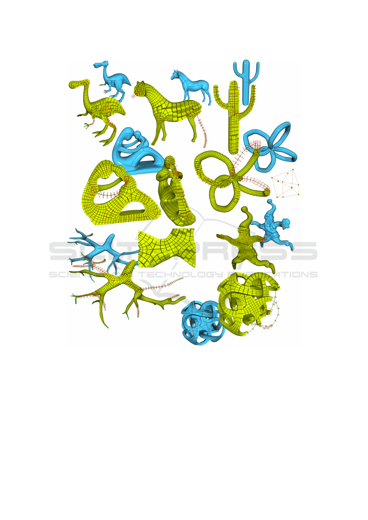
Figure 18: Some meshes obtained with our method. The skeleton (black) extracted from the surface mesh (blue) and connec-
tion surfaces (red) are displayed along with the hexahedral cells (yellow). Quality measures for these meshes are indicated in
Table 1. From top-left to bottom-right: Dinopet, Horse, Cactus, Fertility, Cycles, Vessel, Santa and Metatron.
subsequent refinement, adaptation to the domain ge-
ometry, and cells shape optimization.
Improvements on this work are of course still pos-
sible to get better results. (Livesu et al., 2016) pro-
poses a method to adapt the mesh locally based on
radius variations along branches through the insertion
of patterns of hexahedra that lead to an increase or
decrease of the number of hexahedra within a chunk.
This resolution adaptation has a strong impact on the
final result quality and usability. Our perspectives in-
clude its adaptation to our method.
At the core of our proposition, the sphere parti-
tioning method can also be improved. Our current
algorithm is led by local choices based on angles. It
produces acceptable results, but a canonical solution
of the sphere partitioning problem could be highly
valuable.
Hexahedral Mesh Generation for Tubular Shapes using Skeletons and Connection Surfaces
53

ACKNOWLEDGEMENTS
Thanks to the Hexalab platform (Bracci et al., 2019)
for providing tools and datasets from previous studies.
REFERENCES
Bracci, M., Tarini, M., Pietroni, N., Livesu, M., and
Cignoni, P. (2019). Hexalab.net: An online viewer for
hexahedral meshes. Computer-Aided Design, 110:24
– 36.
Fuentes Suárez, A. J. and Hubert, E. (2018). Scaffolding
skeletons using spherical voronoi diagrams: feasibil-
ity, regularity and symmetry. Computer-Aided Design,
102:83–93.
Gao, X. and Chen, G. (2016). A local frame based hexa-
hedral mesh optimization. In Proceedings of the 25th
International Meshing Roundtable.
Gao, X., Huang, J., Xu, K., Pan, Z., Deng, Z., and Chen, G.
(2017). Evaluating hex-mesh quality metrics via cor-
relation analysis. Computer Graphics Forum, 36:105–
116.
Hijazi, Y., Bechmann, D., Cazier, D., Kern, C., and Th-
ery, S. (2010). Fully-automatic branching recon-
struction algorithm : application to vascular trees.
In Shape Modeling International (SMI10), Aix-en-
Provence, 21-23 June.
Komaritzan, M. and Botsch, M. (2018). Projective skinning.
Proc. ACM Comput. Graph. Interact. Tech., 1(1).
Kowalski, N., Ledoux, F., and Frey, P. (2016). Smoothness
driven frame field generation for hexahedral meshing.
Computer-Aided Design, 72:65 – 77. 23rd Interna-
tional Meshing Roundtable Special Issue: Advances
in Mesh Generation.
Kremer, M., Bommes, D., Lim, I., and Kobbelt, L.
(2014). Advanced automatic hexahedral mesh genera-
tion from surface quad meshes. In Proceedings of the
22nd International Meshing Roundtable, pages 147–
164.
Lévy, B. and Liu, Y. (2010). Lp centroidal voronoi tes-
sellation and its applications. ACM Transactions on
Graphics, 29(4):119:1–119:11.
Livesu, M., Muntoni, A., Puppo, E., and Scateni, R. (2016).
Skeleton-driven adaptive hexahedral meshing of tubu-
lar shapes. Computer Graphics Forum, 35(7):237–
246.
Livesu, M., Pietroni, N., Puppo, E., Sheffer, A., and
Cignoni, P. (2020). Loopycuts: Practical feature-
preserving block decomposition for strongly hex-
dominant meshing. ACM Transactions on Graphics
(SIGGRAPH), 39(4).
Livesu, M., Sheffer, A., Vining, N., and Tarini, M. (2015).
Practical hex-mesh optimization via edge-cone recti-
fication. ACM Transactions on Graphics, 34(4).
Livesu, M., Vining, N., Sheffer, A., Gregson, J., and
Scateni, R. (2013). Polycut: Monotone graph-cuts for
polycube base-complex construction. Transactions on
Graphics (Proc. SIGGRAPH ASIA 2013), 32(6).
Lu, J. H.-C., Quadros, W. R., and Shimada, K. (2017). Eval-
uation of user-guided semi-automatic decomposition
tool for hexahedral mesh generation. Journal of Com-
putational Design and Engineering, 4(4):330 – 338.
Na, H.-S., Lee, C.-N., and Cheong, O. (2002). Voronoi
diagrams on the sphere. Computational Geometry,
23(2):183–194.
Nieser, M., Reitebuch, U., and Polthier, K. (2011). Cube-
Cover - Parameterization of 3D Volumes. Computer
Graphics Forum.
Panotopoulou, A., Ross, E., Welker, K., Hubert, E., and
Morin, G. (2018). Scaffolding a skeleton. Research
in Shape Analysis, 12:17–35.
Peng, C.-H., Zhang, E., Kobayashi, Y., and Wonka, P.
(2011). Connectivity editing for quadrilateral meshes.
ACM Transactions of Graphics, 30(6).
Schneiders, R. (1996). A grid-based algorithm for the gen-
eration of hexahedral element meshes. Engineering
with Computers, 12(3):168–177.
Sokolov, D., Ray, N., Untereiner, L., and Lévy, B. (2016).
Hexahedral-dominant meshing. ACM Transactions on
Graphics, 35(5).
Tagliasacchi, A., Alhashim, I., Olson, M., and Zhang, H.
(2012). Mean curvature skeletons. Computer Graph-
ics Forum (Proc. of the Symposium on Geometry Pro-
cessing).
Usai, F., Livesu, M., Puppo, E., Tarini, M., and Scateni,
R. (2015). Extraction of the quad layout of a triangle
mesh guided by its curve skeleton. ACM Transactions
on Graphics, 35:1–13.
Verhetsel, K., Pellerin, J., and Remacle, J.-F. (2019). Find-
ing hexahedrizations for small quadrangulations of the
sphere. ACM Transactions on Graphics, 38(4).
Wang, W., Jüttler, B., Zheng, D., and Liu, Y. (2008). Com-
putation of rotation minimizing frames. ACM Trans-
actions on Graphics, 27.
GRAPP 2021 - 16th International Conference on Computer Graphics Theory and Applications
54
