
BASH: Biomechanical Animated Skinned Human for Visualization of
Kinematics and Muscle Activity
R. Schleicher
1
, M. Nitschke
1
, J. Martschinke
2
, M. Stamminger
2
, B. M. Eskofier
1
, J. Klucken
3
and
A. D. Koelewijn
1
1
Machine Learning and Data Analytics Lab, Department Artificial Intelligence in Biomedical Engineering (AIBE),
Friedrich-Alexander-Universit
¨
at Erlangen-N
¨
urnberg (FAU), Germany
2
Chair of Visual Computing, Department of Computer Science, Friedrich-Alexander-Universit
¨
at Erlangen-N
¨
urnberg
(FAU), Germany
3
Department of Molecular Neurology, University Hospital Erlangen, Friedrich-Alexander-Universit
¨
at Erlangen-N
¨
urnberg
(FAU), Germany
Keywords:
Biomechanics, Surface Visualization, Animation, Statistical Human Model, Kinematics, Muscle Activity.
Abstract:
Biomechanical analysis of human motion is applied in medicine, sports and product design. However, visual-
izations of biomechanical variables are still highly abstract and technical since the body is visualized with a
skeleton and muscles are represented as lines. We propose a more intuitive and realistic visualization of kine-
matics and muscle activity to increase accessibility for non-experts like patients, athletes, or designers. To this
end, the Biomechanical Animated Skinned Human (BASH) model is created and scaled to match the anthro-
pometry defined by a musculoskeletal model in OpenSim file format. Motion is visualized with an accurate
pose transformation of the BASH model using kinematic data as input. A statistical model contributes to a
natural human appearance and realistic soft tissue deformations during the animation. Finally, muscle activity
is highlighted on the model surface. The visualization pipeline is easily applicable since it requires only the
musculoskeletal model, kinematics and muscle activation patterns as input. We demonstrate the capabilities
for straight and curved running simulated with a full-body musculoskeletal model. We conclude that our visu-
alization could be perceived as intuitive and better accessible for non-experts than conventional skeleton and
line representations. However, this has to be confirmed in future usability and perception studies.
1 INTRODUCTION
The progress in biomechanics has brought vast op-
portunities to analyse human movement (Ezati et al.,
2019). Biomechanical simulations enable a recon-
struction of recorded motion or prediction of a novel
movement (Ezati et al., 2019; Falisse et al., 2019; Lin
and Pandy, 2017; Nitschke et al., 2020). Humans
are represented with physics-based musculoskeletal
models to calculate biomechanical variables such as
joint angles, joint moments and muscle activation. As
the methodology continues to develop, applications
in medicine, sports and product design are emerg-
ing. Hence, multiple user groups besides biomechan-
ical engineers will inspect and interpret biomechan-
ical variables in future. For example, a visualiza-
tion of Parkinson-specific motion might be exploited
for modern patient education (Udow et al., 2018)
or for visual feedback for gait retraining (Richards
et al., 2018; Van den Noort et al., 2015). As alter-
native to video analysis in sports which is restricted
to a capture volume and might not always be avail-
able, motion could be reconstructed from inertial sen-
sor data using musculoskeletal simulation (Dorschky
et al., 2019b) and later be visualized for analysis
with a human model. This reconstruction has the
additional advantages that internal variables, such as
movement-related forces, could be analysed for in-
jury prevention (Bencke et al., 2018; Vannatta and
Kernozek, 2015). Although musculoskeletal simu-
lations can support product design of, for example,
prostheses (Fey et al., 2012; Koelewijn and van den
Bogert, 2016) or shoes (Dorschky et al., 2019a), they
lack a proper tool to communicate design decisions
with non-experts. In order to inspect and interpret
the simulated biomechanical variables, a visualization
has to be intuitive and accessible for non-experts like
patients, athletes, or designers.
1.1 Related Work
A wide variety of biomechanical simulation frame-
works exists for modelling and analysis of mus-
culoskeletal models. AnyBody (Damsgaard et al.,
Schleicher, R., Nitschke, M., Martschinke, J., Stamminger, M., Eskofier, B., Klucken, J. and Koelewijn, A.
BASH: Biomechanical Animated Skinned Human for Visualization of Kinematics and Muscle Activity.
DOI: 10.5220/0010210600250036
In Proceedings of the 16th International Joint Conference on Computer Vision, Imaging and Computer Graphics Theory and Applications (VISIGRAPP 2021) - Volume 1: GRAPP, pages
25-36
ISBN: 978-989-758-488-6
Copyright
c
2021 by SCITEPRESS – Science and Technology Publications, Lda. All rights reserved
25
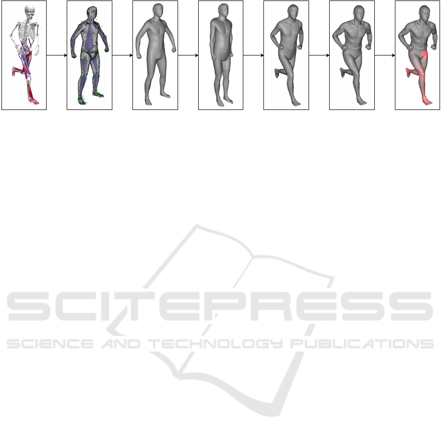
Figure 1: Proposed processing pipeline to visualize kinematics and muscle activity of biomechanical simulations using a
skinned human model. From left to right it shows the musculoskeletal model visualized with OpenSim (Seth et al., 2018)
and the proposed processing steps: creation of the BASH baseline model, scaling, initial pose matching, pose transformation,
statistical deformation, and visualization of muscle activity.
2006), D-Flow (Geijtenbeek et al., 2011; Van den
Bogert et al., 2013) and LifeModeler (McGuan,
2001) are commercial software packages and Open-
Sim (Delp et al., 2007; Seth et al., 2018) is an open-
source software package. OpenSim is reaching a
worldwide and rapidly growing community due to its
accessibility (Seth et al., 2018) and its support for for-
ward dynamics to predict novel movements. Abella
and Demircan (2019) incorporated musculoskeletal
models derived from OpenSim into the Unity envi-
ronment to simultaneously track and analyse motion.
These software solutions focus on the simulation
functionality and on an accurate representation of the
modelled body segments and muscle tendon units
(MTUs). Hence, they provide an interactive interface
displaying bones only as simple geometric shapes and
muscles as two-dimensional (2D) line representations
(see for example the OpenSim visualization in Fig-
ure 1, left). Muscle activity is shown by color coding
of the muscle pathways. Although these abstract and
technical visualizations are well suited for users with
biomechanical background, they are not appropriate
for non-experts. The visualization of musculoskele-
tal simulations was integrated into a computer-aided
design environment to facilitate user-centered design,
but the model was still visualized with a skeleton and
muscle pathways (Kr
¨
uger and Wartzack, 2015).
Instead of using muscle pathways, muscles can be
modelled with volumetric geometries to increase ac-
curacy of the simulations or to study muscle deforma-
tion (Blemker and Delp, 2005; Maurice et al., 2009;
Peeters and Pronost, 2014; Teran et al., 2003; Teran
et al., 2005). However, volumetric muscle models are
rarely used in biomechanical simulations since com-
plexity of model creation and simulation increases
considerably. Others include volumetric muscle mod-
els only for visualization of computed muscle activ-
ity to increase interpretability without using them for
simulation (Pronost et al., 2011; Van den Bogert et al.,
2013). Pronost et al. (2011) provided an OpenSim
plugin with predefined muscle geometries that can be
assigned to the MTUs of the musculoskeletal model.
However, none of these visualizations for biomechan-
ical analysis uses three-dimensional (3D) skinned hu-
man models. An overlay of volumetric muscle shapes
on a video stream for color coding of muscle activ-
ity (Murai et al., 2010) might be closer to reality
than the existing skeletal representations. This ap-
proach operates in real-time based on electromyog-
raphy measurements. Nevertheless, it is not appli-
cable if no video recording is available, which is the
case when motion is reconstructed from inertial sen-
sor data or when novel motions are predicted. Hence,
3D skinned human models might be the most intuitive
visualization of reconstructed and predicted biome-
chanical movements especially for non-specialists.
In computer graphics, biomechanical and physi-
cal knowledge is also used to increase realism of hu-
man animations. Muscle and soft tissue deforma-
tion are modelled with mass-spring systems, finite el-
ement method, or finite volume method (Aubel and
Thalmann, 2001; Lee et al., 2009; Lee et al., 2012;
Murai et al., 2017; Sueda et al., 2008). Geometries
have to be modelled by hand or based on medical
image data and simulations often have high compu-
tational demands. Hence, these methods are usually
only applied for single muscles or body parts. Alter-
natively, human surface models can be directly an-
imated with data-driven methods without explicitly
taking the deformation of underlying structures into
account (Lee et al., 2012). An elegant way to cre-
ate a virtual skin envelope is to use statistical para-
metric shape models, which are often used for ani-
mation of human subjects in motion (Cheng et al.,
2018). Anguelov et al. (2005) first implemented a
parametric model for pose-induced soft tissue defor-
mation and body shape variation to perform Shape
Completion and Animation of PEople (SCAPE). Pa-
rameters are learned from 3D full-body scans of var-
ious poses and people. They separate rigid (skele-
GRAPP 2021 - 16th International Conference on Computer Graphics Theory and Applications
26

tal) and non-rigid deformations to simplify mathemat-
ically formulation and to accelerate the learning al-
gorithm. However, the SCAPE model determines the
soft tissue deformation based on only a static pose and
does not take muscle activation or dynamics into ac-
count. The Dyna (Pons-Moll et al., 2015) model also
reflects dynamic soft tissue deformations caused by
motion. Nevertheless, the statistical surface models
used in computer graphics lack the connection to tra-
ditional biomechanical simulations of musculoskele-
tal models. Torque-driven animation is intensively in-
vestigated to obtain authentic human motion instead
of prescribing the motion (Geijtenbeek and Pronost,
2012; Jiang et al., 2019). But, in contrast to mus-
cle control, torque control does not generate biologi-
cally reasonable motion since human torques are not
limited to a constant range and the energy function
minimizing torques does not reflect the human mus-
culoskeletal system (Jiang et al., 2019).
1.2 Purpose
In this work, we aim to develop a method to ani-
mate 3D human surface models for biomechanical
analysis. We propose the Biomechanical Animated
Skinned Human (BASH) model which provides an
animated skinned visualization of a musculoskeletal
model defined in the commonly used OpenSim for-
mat (Seth et al., 2018) without requiring any addi-
tional data. The body proportions of the virtual hu-
man are automatically adapted to match the subject-
specific dimensions of the musculoskeletal model.
Kinematic coordinates are processed to apply pose
transformation and thus to animate the skin envelope
in order to reflect a movement. The statistical model
SCAPE (Anguelov et al., 2005) should yield natu-
ral human appearance and realistic soft tissue defor-
mations. Furthermore, muscle activity of underlying
MTUs is highlighted on the surface which enables a
kinetic analysis. We evaluate the pipeline with ten
full-body musculoskeletal models scaled to each sub-
ject and simulated data of straight and curved running.
Though this assumption has to be proven in further
studies, we assume that our representation is more in-
tuitive than conventional visualizations and therefore
more accessible, especially for users without biome-
chanical background.
1.3 Outline
The processing pipeline is summarized in Figure 2.
In Section 2, the biomechanical data and the SCAPE
model are introduced. In Section 3, the generation of
the baseline version of the proposed BASH model is
described. Section 4 explains how the BASH model
was matched to a subject-specific musculoskeletal
model. Section 5 covers the animation and statisti-
cal deformation of the surface model. The visual-
ization of muscle activity is presented in Section 6.
The results of the experiments and analyses from
Section 7 are evaluated and discussed in Section 8.
The paper concludes with a short summary and out-
look in Section 9. The code is publicly available at
https://github.com/mad-lab-fau/BASH-Model.
2 VISUALIZATION INPUT
A musculoskeletal model, kinematics and muscle ac-
tivity serve as biomechanical input for the visualiza-
tion (see Figure 2). Since OpenSim (Seth et al., 2018)
is a widely used open-source software for muscu-
loskeletal simulations, its data format and framework
is used. All variables belonging to the biomechani-
cal data are denoted in this paper with a hat ˆ·. The
musculoskeletal model consists of a skeletal struc-
ture where bone segments are connected via moving
joints
ˆ
J = {
ˆ
J
0
,...,
ˆ
J
N
ˆ
J
−1
}. Joints can be manipulated
using generalized coordinates
ˆ
~q(t), thus defining the
kinematics of the model over time t. Virtual mark-
ers
ˆ
M = {
ˆ
~m
0
,...,
ˆ
~m
N
ˆ
M
−1
} are commonly attached to
the musculoskeletal model for subject-specific model
scaling and inverse kinematics. Muscles are described
by MTUs with 2D pathways
ˆ
E(t) and maximum iso-
metric forces
ˆ
f
max
, among other parameters. Forces
acting during a movement are encoded as muscle ac-
tivation ˆa(t) of a specific MTU.
To obtain a realistic surface representation of
the musculoskeletal model, the human statistical
SCAPE (Anguelov et al., 2005) model is used as ba-
sis. SCAPE, the first established method of its kind,
provides a sophisticated framework for our approach.
All variables belonging to the SCAPE model are de-
noted in this paper with a tilde ˜·. Training of pose
parameters
˜
Q and shape parameters
˜
D was performed
on full-body 3D scans from a large data set (Yang
et al., 2014). Additionally, training of the shape co-
efficients was refined using further 3D scans (Hasler
et al., 2009b; Hasler et al., 2009a; Hasler et al., 2010).
In order to eliminate any pose deviations for the shape
learning, a volume aware non-rigid mesh registration
was performed (Colaianni et al., 2014). Training gen-
erates a template mesh
˜
V which corresponds to the
envelope of a virtual person in static pose with aver-
age shape parameters.
BASH: Biomechanical Animated Skinned Human for Visualization of Kinematics and Muscle Activity
27
Musculoskeletal Model Muscle DataKinematics Biomechanical Data
SCAPE Model
Scaling of Body
Proportions
Initial Pose
Matching
Pose
Transformations
Transformations
into SCAPE Space
Area of
Influence
Intensity
Visualization
Baseline Model
Pose
Transformations
Pose
Transformations
Transformations
into SCAPE Space
Transformations
into SCAPE Space
Area of
Influence
Area of
Influence
Intensity
Visualization
Intensity
Visualization
Figure 2: Processing pipeline to visualize kinematics and muscle activity using a skinned human surface model. The input of
the pipeline (grey rectangles) and the processing steps (green rectangles) are explained in the following sections.
3 BASELINE MODEL
The simulated generalized coordinates of the mus-
culoskeletal model cannot directly be applied to the
SCAPE model due to differences in skeletal struc-
tures, body proportions and initial poses which would
lead to an incorrect visualization. In particular, the
disparate definition of the skeletal structure of both
models is a challenge. The BASH model is developed
to overcome the differences and to generate an accu-
rate yet realistic 3D surface representation of the sim-
ulated musculoskeletal motion. Figure 3 illustrates
the three components which define the BASH model:
• Mesh geometry to represent the model’s surface
and virtual appearance of the skinned human
• Articulated skeleton to enable surface deforma-
tions using the interconnected bones
• Marker attachments to create a clear relation-
ship to the musculoskeletal model for scaling of
body proportions and initial pose matching
The SCAPE template mesh
˜
V is used as the
BASH geometry V with vertices ~v. A skeletal ar-
mature with the same hierarchical composition as the
musculoskeletal model is placed into the mesh by rig-
ging the bones B = {B
0
,...,B
N
B
−1
} as defined by
the joints
ˆ
J of the musculoskeletal model. Devia-
tions in position and dimensions can be neglected
since body proportions will be scaled in a separate
step. Automatic computed skinning weights Ω
~v
=
{ω
B
0
,...,ω
B
N
Ω
−1
} connect the skeleton and the mesh
geometry (Kavan et al., 2009). The weight ω
B
deter-
mines by how much the transformation of a bone B
is transferred to its assigned vertices. The maximum
number of influencing bones for one vertex is set to
N
Ω
= 4 which is common in character animation due
to efficiency in hardware (McLaughlin et al., 2011).
Improperly assigned weights are corrected manually.
Finally, virtual markers M = {~m
0
,...,~m
N
M
−1
} cor-
humerus_l
ulna_l
hand_l
radius_l
torso
pelvis
humerus_r
ulna_r
hand_r
radius_r
tibia_l
femur_lfemur_r
tibia_r
talus_l
calcn_l
toes_l
talus_r
calcn_r
toes_r
Figure 3: The conceptual design of the generic BASH
model on the basis of SCAPE (Anguelov et al., 2005). It in-
corporates a surface mesh, an underlying articulated skele-
ton and attached marker points.
responding to the markers
ˆ
M of the musculoskeletal
model are attached to the BASH model at landmark
points near the surface to establish a relationship be-
tween the models. The markers are used to determine
body proportions and to match the initial poses. The
resulting generic version of the BASH model reflects
a non-scaled musculoskeletal model with a specific
anatomical structure.
4 MODEL MATCHING
The baseline model has to be matched to a scaled ver-
sion of the musculoskeletal model in its initial pose.
This preprocessing step is performed once for a sub-
ject before animation.
4.1 Scaling of Body Proportions
In musculoskeletal modelling, individual variations in
body proportions are taken into account by adjust-
GRAPP 2021 - 16th International Conference on Computer Graphics Theory and Applications
28
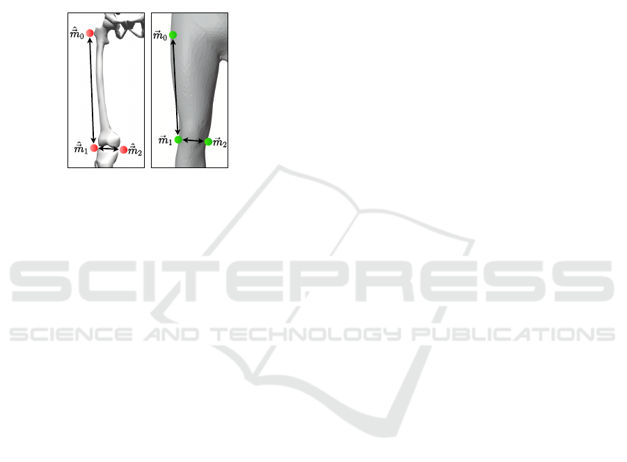
ing the body segments using recorded marker posi-
tions (Delp et al., 2007). Using the same principle,
we match the subject’s anthropometry and ensure a
realistic visualization by scaling segment sizes based
on the defined virtual marker positions (see Figure 4).
For each bone B, an uniform scaling transformation
S
B
is determined as average ratio between marker
distances of the musculoskeletal model and of the
generic BASH model.
Figure 4: 3D positions of attached markers
ˆ
~m and ~m are
used to scale body segments.
However, the scaling with matrix S
B
is not ap-
plied directly in bone space since a change of bone
size should only be applied to a particular bone B and
not inherited through the skeletal hierarchy. There-
fore, the new position N
0
B
of a bone B is computed by
propagation through the skeleton starting at the root
node:
N
0
B
= N
0
B
parent
· N
B
· S
B
· S
−1
B
parent
, (1)
where N
B
is the 3D state of the bone before scal-
ing. Scaling of the parent bone B
parent
is reversed
by multiplying the inverse scaling matrix S
−1
B
parent
to
avoid inheritance. For the root node, N
0
B
parent
and
S
−1
B
parent
are the identity matrix. To scale the generic
mesh, the new position N
0
B
is multiplied by the in-
verse offset matrix O
B
W
−1
which denotes the projec-
tion from bone space B to world space W . The result-
ing transformation matrices are applied to the markers
and vertices of the generic mesh. Consequently, lin-
ear blend skinning shifts all vertices ~v by the extent
of the defined skinning weights Ω
~v
which simultane-
ously prevents hard borders and noticeable gaps be-
tween limbs (Magnenat-Thalmann et al., 1988).
4.2 Initial Pose Matching
Within OpenSim, pose transformations are specified
by generalized coordinates. However, the relation be-
tween the initial pose of the musculoskeletal model
and the scaled BASH model is unknown and has to be
established before deploying any pose transformation.
This relation is described by a change of basis, i.e. by
a projection P
ˆ
J
B
from the coordinate system of joint
ˆ
J
of the musculoskeletal model to the corresponding co-
ordinate system of bone B of the scaled BASH model.
The generalized coordinates
ˆ
~q define the pose of the
musculoskeletal model which matches the initial pose
of the scaled BASH model. They are obtained by in-
verse kinematics using the OpenSim application pro-
gramming interface (API) (version 4.0) (Seth et al.,
2018). In inverse kinematics, the sum of squared dis-
tances between corresponding marker pairs of the two
models is minimized. For the resulting pose, the pro-
jection matrix P
ˆ
J
B
is received from the OpenSim API
as global transformation of the bones with respect to
the ground. Applying the inverse transformations to
the scaled BASH model causes a deformation of the
mesh via skinning weights to match the pose of the
musculoskeletal model.
5 ANIMATION AND
STATISTICAL DEFORMATION
In order to create an animation of the simulated mus-
culoskeletal model, a series of transformations is ap-
plied to the scaled BASH model for each time frame
t of the motion sequence.
5.1 Pose Transformations
Traditional character animation techniques are used to
obtain an animated surface representation of the input
kinematics. The affine transformation
ˆ
T
ˆ
J
(t) contains
the translation and the rotation defined by the gen-
eralized coordinates ~q(t) given in the OpenSim mo-
tion file. For each frame, the input transformation
ˆ
T
ˆ
J
(t) can be directly applied to the bones of the scaled
BASH model in the global coordinate system due to
prior scaling and initial pose matching. The surface
deformation was achieved by linear blend skinning
with previously computed skinning weights. As a re-
sult, the pose transformed BASH model contained the
aggregated animation based on the given movement
of the musculoskeletal model.
5.2 Transformations into SCAPE Space
Statistical transformations introduced in the SCAPE
model (Anguelov et al., 2005) are performed for each
time frame t after the pose transformation to achieve
realistic soft tissue deformations and therefore en-
hance the natural appearance. Before applying the
statistical transformations, the rigid part rotations R
˜
B
BASH: Biomechanical Animated Skinned Human for Visualization of Kinematics and Muscle Activity
29

of all body parts
˜
B have to be determined in order
to define the current pose in the SCAPE space. The
original method proposed by Anguelov et al. (2005)
is adapted to operate without a full body scan of the
target person by using the pose transformed BASH
model from the previous processing step as reference
instead. All vertices of the mesh V serve as refer-
ence points to determine the current pose in corre-
spondence to the template mesh
˜
V which requires
an identical geometric topology of all meshes in the
SCAPE space. The rigid registration of two corre-
sponding body parts
˜
B with N
˜
B
vertices is described as
minimization of the root mean square error (RMSE):
min
R
˜
B
v
u
u
t
1
N
˜
B
N
˜
B
−1
∑
i=0
kR
˜
B
·
˜
~v
i
−~v
i
k
2
, (2)
where
˜
~v and~v are the vertices of the SCAPE template
mesh and the pose transformed BASH model, respec-
tively. This optimization is solved as constrained Pro-
crustes problem (Sch
¨
onemann, 1966) using the Kab-
sch algorithm (Kabsch, 1976) and performing singu-
lar value decomposition (Golub and Reinsch, 1970).
The obtained optimal rotations, i.e. the nearest or-
thogonal matrices, describe the rigid part transforma-
tions R
˜
B
of the SCAPE model.
The main feature of SCAPE is a realistic soft tis-
sue deformation which is achieved by pose-induced
transformations
˜
Q
f
affecting the shape of each face
f on the mesh based on training data and the cur-
rent pose defined by R
˜
B
. The rotations of adja-
cent joints
˜
J
0
,
˜
J
1
and the learned regression vector
˜
~a
f ,i, j
= ( ˜a
0
, ˜a
1
, ˜a
2
, ˜a
3
, ˜a
4
, ˜a
5
, ˜a
6
)
T
from the SCAPE
framework are used to build the matrix:
˜
Q
f
[i, j] =
~
∆
T
R
˜
J
0
,
~
∆
T
R
˜
J
1
,1
T
·
˜
~a
i, j, f
, (3)
where i and j are the row and column indices, re-
spectively.
~
∆
R
˜
J
= (∆
x
,∆
y
,∆
z
)
T
denotes the twist vec-
tor in angle-axis representation (Ma et al., 2004) of
a joint rotation R
˜
J
= R
˜
B
0
· R
T
˜
B
1
composed of adjacent
rigid body parts
˜
B
0
and
˜
B
1
. The body shape is omit-
ted within this paper. Hence, the average shape of
the trained SCAPE template mesh is used by setting
shape deformation matrix
˜
D
f
to the identity matrix
for all faces.
The geometry of the new mesh is retrieved by
minimizing the following non-linear optimization
problem to avoid inconsistencies within the mesh in-
stead of applying the rigid part rotations R
˜
B
f
, pose
dependent deformations
˜
Q
f
, and shape dependent de-
formations
˜
D
f
directly to the vertices~v:
min
~v
N
f
−1
∑
f =0
∑
i=1,2
kR
˜
B
f
·
˜
D
f
·
˜
Q
f
·
˜
~v
f ,i
− (~v
f ,0
−~v
f ,i
)k
2
.
(4)
The two edges~v
f ,0
−~v
f ,i
with i = 1, 2 span the face f
built of the three vertices ~v
f ,0
, ~v
f ,1
, and ~v
f ,2
.
Since the SCAPE framework omits the global po-
sition and orientation of the model in space for com-
putational reasons, it has to be restored. A constrained
orthogonal Procrustes problem is solved globally to
register the SCAPE transformed mesh with the pose
transformed mesh.
6 VISUALIZATION OF MUSCLE
ACTIVITY
In addition to the animation of the model, muscle ac-
tivation is visualized on the model’s surface. The area
of influence and the intensity are computed dynami-
cally during run-time for the current time frame t.
6.1 Area of Influence
In the musculoskeletal model, a muscle
ˆ
F is charac-
terized by a MTU with the 2D pathway
ˆ
E
ˆ
F
(t). The 3D
locations of the connected line segments are defined
by multiple points
ˆ
~p fixed to the articulated skele-
ton. Before visualizing the muscle activity, a map-
ping from the 2D muscle pathways to the surface of
the animated BASH model is established by finding
the smallest distance from an underlying MTU to the
model’s surface. The perpendicular distance d is the
shortest way from the line segment defined by
ˆ
~p
i
and
ˆ
~p
i+1
to a vertex. Vertices with a distance d smaller
than a threshold C
maxDist
are included into the area of
influence of the particular muscle.
6.2 Intensity Visualization
The identified areas of influence are used to highlight
the muscle activation ˆa
ˆ
F
(t) on the surface via color
coding. The force of the muscle contraction scales
linearly with the muscle activation and the maximum
isometric force
ˆ
f
max
ˆ
F
(Thelen, 2003). Hence, the
measure i
ˆ
F
(t) is composed as follows:
i
ˆ
F
(t) =
1
C
maxMeasure
· ˆa
ˆ
F
(t) ·
ˆ
f
max
ˆ
F
. (5)
The constant C
maxMeasure
is introduced to normalize
by the maximum possible value that concentrates on a
point. This enables an objective comparison of move-
ment visualizations of distinct subjects with different
GRAPP 2021 - 16th International Conference on Computer Graphics Theory and Applications
30

muscular constitutions. For each vertex, the measures
i
ˆ
F
(t) of all influencing muscles are accumulated and
added to the red color channel of the mesh. Due to the
implementation in the fragment shader, color values
are interpolated across the faces resulting in smooth
transitions at the boundaries and overlapping areas of
the influencing muscle regions.
7 EXPERIMENTS AND
ANALYSES
We conducted experiments and analyses to confirm
the functionality of the visualization approach using
a full-body musculoskeletal model (Nitschke et al.,
2020). The comprehensive musculoskeletal structure
included 20 joints, 92 MTUs in the lower body and
46 markers.
The scaling functionality and the initial pose
matching were evaluated with ten male test sub-
jects. The generic musculoskeletal model (Nitschke
et al., 2020) was scaled using the OpenSim scaling
tool (Delp et al., 2007) to match the marker data of
static trials of nine subjects (Dorschky et al., 2019b)
(subject A to I). Additionally, an already scaled mus-
culoskeletal model was used as subject J (Nitschke
et al., 2020). To evaluate the scaling, the height H of
the scaled BASH model was determined as the dis-
tance between the smallest and greatest y-coordinate
of the mesh in the initial pose. The height should cor-
relate with the body height of the subject.
The pose transformation and animation of the
BASH model was analysed for subject J with simu-
lated kinematics of straight running and curved run-
ning with 50 time samples available in the OpenSim
file format (Nitschke et al., 2020). The proposed sur-
face visualization of the muscle activity was tested
with corresponding simulated muscle activation pat-
terns of the motions and compared to the line repre-
sentation in the OpenSim environment.
8 RESULTS AND DISCUSSION
Figure 5 presents the final surface visualization in
comparison to the visualization from OpenSim (Seth
et al., 2018). In the following, the individual process-
ing and transformation steps are discussed separately.
8.1 Scaling of Body Proportions
The scaling of body proportions is an essential step
for a representative visualization. An incorrect model
(a) (b) (c)
Figure 5: Final visualization of the kinematics including
the muscle activation on the surface compared to the Open-
Sim (Seth et al., 2018) representation as reference. (a) and
(b) show frontal and sagittal view of simulated straight run-
ning, respectively. (c) shows superimposed frames of simu-
lated curved running.
size would lead to incorrect postures and would in-
fluence the analysis. For example, the ground contact
time (Mooses et al., 2018) or foot clearance (Begg
et al., 2007) are of interest for biomechanical analy-
ses of gait, but would be erroneous.
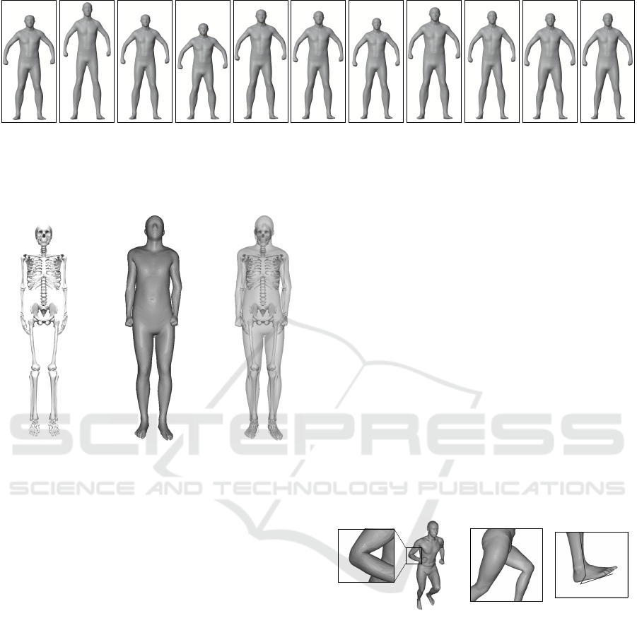
Figure 6 shows the outcomes of the body part
scaling for the ten subjects. The height H of the
BASH model is greater than the actual body height
for all subjects except for subject D and J. The mean
and standard deviation of the absolute error is 6.7 ±
4.8cm. Nevertheless, the proposed scaling is bene-
ficial since the height of the scaled model is always
closer to the body height than the generic model. We
propose uniform scaling to produce robust result even
when few markers are present. However, non-uniform
scaling with individual scale factors for each dimen-
sion might be beneficial.
Nevertheless, the comparison of heights has to be
interpreted with caution since marker placement or
scaling of the musculoskeletal model can introduce
errors as well. Furthermore, the estimated height H
of the BASH model depends on the initial pose and
might change when the model is transformed into
SCAPE space. Also the skinning weights influence
the shape and thus the scaling and height.
8.2 Initial Pose Matching
The quality of the mapping P
ˆ
J
B
between the initial
pose of the musculoskeletal model and the scaled
BASH model influences the accuracy of the following
pose transformations. Visual inspection shows that
the BASH model is brought into a pose very similar to
the pose of the musculoskeletal model (see Figure 7).
However, the surface geometry does not completely
envelope the musculoskeletal skeleton especially at
the extremities due to missing marker data and miss-
ing mobility of hands and feet.
In inverse kinematics, the objective is to mini-
BASH: Biomechanical Animated Skinned Human for Visualization of Kinematics and Muscle Activity
31
178 cm
(a) Sub. A
187 cm
(b) Sub. B
180 cm
(c) Sub. C
178 cm
(d) Sub. D
186 cm
(e) Sub. E
185 cm
(f) Sub. F
176 cm
(g) Sub. G
189 cm
(h) Sub. H
180 cm
(i) Sub. I
195 cm
(j) Sub. J (k) Gen.
Figure 6: Frontal view of the scaled models before pose transformation and transformation into SCAPE space. Body heights
reported by the subjects are displayed in the upper right corners. As reference, the generic model with a height H of 185 cm
is displayed.
(a) (b) (c)
Figure 7: Visualization after the initial pose matching. (a),
(b), and (c) show the skeletal representation of subject J in
OpenSim (Seth et al., 2018), the proposed surface represen-
tation, and an overlay of both for comparison, respectively.
mize the marker tracking error. For the ten test sub-
jects, the mean and standard deviation of the RMSE
and of the maximum marker error is 2.1 ± 1.5 cm
and 5.0 ± 3.0cm, respectively. The error is therefore
mainly within the range of the OpenSim recommen-
dation (OpenSim, 2020). Similar to optical motion
capture, the quality of the pose estimation highly de-
pends on the marker placement.
8.3 Pose Transformation
The pose transformation is the main step of to ani-
mate the BASH model according to an input motion
sequence. Due to the initial pose matching, kinemat-
ics are directly applied to the mesh using linear blend
skinning which is commonly used in traditional com-
puter animation. Although it produces accurate vi-
sualizations, some regions like elbow and hip are af-
fected by strong deformations (see Figure 1).
8.4 Transformation into SCAPE Space
The transformation into SCAPE space makes use of
a large training data set of full-body scans and thus
can enrich the natural appearance of the animated hu-
man envelope. The SCAPE algorithm includes pose-
induced deformations
˜
Q
f
for realistic soft tissue de-
formation, e.g. muscle contractions, and shape de-
pendent deformations
˜
D
f
for realistic representation
of the body structure.
The undesired strong deformations of the mesh at
elbow and hip are reduced by the transformation into
SCAPE space (see Figure 8a and 8b). Although the
realism is enhanced, the accuracy of the surface rep-
resentation suffers (see Figure 8c). Especially slight
offsets at the feet might impact gait analysis where
ground contact is crucial (Begg et al., 2007; Mooses
et al., 2018).
(a)
(b) (c)
Figure 8: Views after transformation into SCAPE space for
straight running. In (c) the articulated skeleton is overlaid.
The global registration of position and orienta-
tion after transformation into SCAPE space produces
robust results due to the use of 12500 vertex corre-
spondences. Alternatively, the pose transformation of
the root bone could be used to apply the global po-
sition and orientation. Nevertheless, this would not
acknowledge the fact that the SCAPE transformed
model is fixed to the global coordinate system with
a vertex at the right foot instead of the root bone.
We did not yet include shape dependent deforma-
tions by applying the shape coefficients provided by
the SCAPE framework, which would enable a rep-
GRAPP 2021 - 16th International Conference on Computer Graphics Theory and Applications
32
resentation of individual’s anthropometry. For real-
ism and identification with a virtual self, authenticity
of a subject-related representation is key (Waltemate
et al., 2018). Other statistical human models (Cheng
et al., 2018) are more complex, but might also further
increase the realism of the representation. Blending
of strong deformations is improved (Hirshberg et al.,
2012; Jain et al., 2010) and the Skinned Multi Person
Linear Model (SMPL) (Loper et al., 2015) produced
the most accurate results. SMPL+H (Romero et al.,
2017), a recent extension of SMPL, allows posing and
animation of individual fingers which would lead to
an overall more natural representation. A slightly dif-
ferent aspect is included in the Dyna (Pons-Moll et al.,
2015) model as it produces realistic dynamical soft
tissue deformations during movement.
However, increased realism might not benefit the
visualization. Lungrin et al. (2015) found that a
nearly realistic human visualization evoke a strange
feeling for an observer referred as the uncanny val-
ley effect. Whether the visualization is perceived as
realistic and whether subjects can identify themselves
with the visualized model has to be confirmed in stud-
ies, especially with respect to the application and user
group. In general, a balance between fidelity and de-
gree of realism has to be found.
8.5 Visualization of Muscle Activity
MTUs are projected orthogonally onto the model sur-
face to visualize muscle activity since it does not
require additional data in contrast to other methods
and allows therefore for easy visualization of various
MTU sets. Furthermore, we hypothesize that a vi-
sualization on the surface is more accessible for non
experts than volumetric muscle visualizations (Murai
et al., 2010; Pronost et al., 2011; Van den Bogert et al.,
2013) or line representations of OpenSim (Seth et al.,
2018) or AnyBody (Damsgaard et al., 2006).
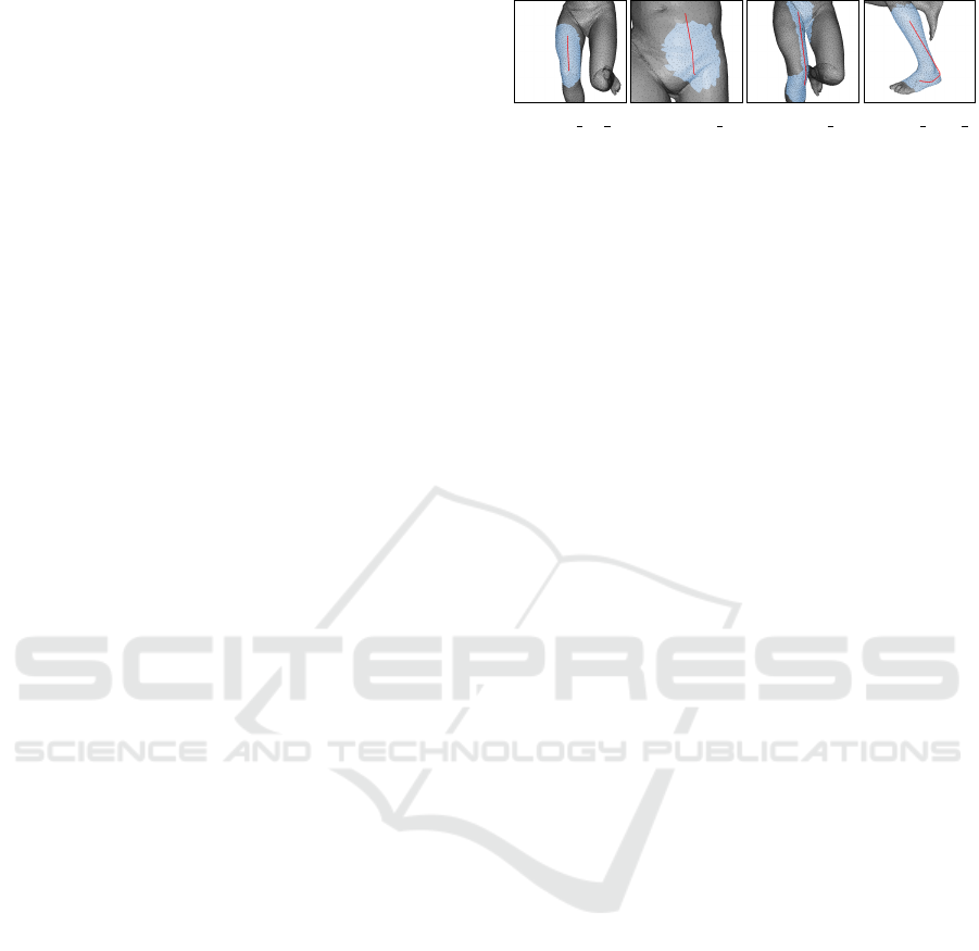
Depending on the application, the maximal dis-
tance C
maxDist
has to be chosen in order to represent
the underlying MTUs well. For all figures in this pa-
per, C
maxDist
is set to 8 cm as this produces appropriate
results (see Figure 9). Alternatively, the maximum
isometric force
ˆ
f
max
ˆ
F
of each muscle could be in-
cluded in the definition of the maximal distance since
it is related to muscle volume.
Although the area is determined well for most
muscles, it overflows into the other leg for the gracilis
(see Figure 9c) and covers the complete shank instead
of the rear part of the calf for the peroneus longus
(see Figure 9d). This could be avoided by consider-
ing the orientation of the muscles with respect to the
attached bones. Additionally, anatomical knowledge
(a) vas int r (b) psoas l (c) grac r (d) per long l
Figure 9: Areas of influence (blue) assigned to the corre-
sponding muscle pathways (red) using a maximal distance
C
maxDist
of 8cm.
could be included, though this would limit the usabil-
ity of the approach for other musculoskeletal models.
Constraining the curvature in tangent space (Dennis
et al., 1997) or using alternative algorithms like re-
gion growing (Adams and Bischof, 1994) could pre-
vent propagation across valleys. Further improve-
ments might be achieved by using barycentric coor-
dinates (Rustamov, 2010) to overcome the limitation
to vertex assignments.
For color coding of the determined area, the in-
tensity is normalized with a constant C
maxMeasure
=
14000N to ensure comparability of the visualization
across different motion sequences or subjects. In-
tensity normalization is for example important when
evaluating temporal progress of diseases, gait train-
ing, or running technique of athletes or when com-
paring body constitutions or designs of equipment.
The constant C
maxMeasure
should be chosen specific to
the musculoskeletal model and application. Since the
intensity measure i
ˆ
F
is added to the red color chan-
nel, the value of the red color channel could exceed
its limits for inappropriate constants and would be
cropped.
The color coding of the muscle activation is vi-
sually compared to the line representation of Open-
Sim (Seth et al., 2018) (see Figure 1). The mus-
cle activation is highlighted plausibly on the surface
with smooth transitions at borders and overlapping re-
gions due to the color interpolation of the fragment
shader. In Figure 5, kinematics and muscle activation
of straight and curved running are visualized. Es-
pecially for people with little biomechanical knowl-
edge, the surface representation likely appears more
vivid and realistic. At the same time, it does not re-
quire additional data and can easily be applied to dif-
ferent musculoskeletal models. Hence, the proposed
visualization of the muscle activity might offer a use-
ful alternative compared to the 2D line (Damsgaard
et al., 2006; Seth et al., 2018) or volumetric represen-
tation (Murai et al., 2010; Pronost et al., 2011; Van
den Bogert et al., 2013).
BASH: Biomechanical Animated Skinned Human for Visualization of Kinematics and Muscle Activity
33

9 CONCLUSION
We have presented a visualization pipeline to animate
a skinned representation for biomechanical analysis
of kinematics and muscle activity. The goal was to
make biomechanical analysis more intuitive and re-
alistic and increase accessibility for non-experts. To
this end, we developed the BASH model to establish
a bridge between the musculoskeletal model and a
statistical surface model. Traditional animation char-
acter techniques and the SCAPE framework enabled
body part scaling, pose transformations and realistic
surface deformations for the input kinematics. Ad-
ditionally, muscle activity related to the motion se-
quence is highlighted on the model’s surface. Still,
our approach does not require more input data than a
traditional biomechanical approach: a musculoskele-
tal model, kinematic data and muscle activation. This
ensures high usability and makes it easily applicable
to other musculoskeletal models.
The proposed approach was evaluated us-
ing scaled musculoskeletal models of ten sub-
jects (Dorschky et al., 2019b; Nitschke et al., 2020)
and data of simulated straight and curved run-
ning (Nitschke et al., 2020). Our method achieved a
realistic person-specific representation of the biome-
chanical input. Beside minor discrepancies, body
part dimensions and the movement sequence was re-
flected accurately compared to state-of-the-art repre-
sentations like OpenSim (Seth et al., 2018). The pro-
posed 3D skinned human surface model seemed more
accessible for non-experts, especially the visualiza-
tion of muscular activity on the surface might offer
an intuitive representation.
However, various topics could be investigated for
further improvements. For applications where real-
time feedback is required, such as gait retraining,
Realtime-SCAPE (Chen et al., 2016) could be inves-
tigated. Furthermore, it might be possible to learn
the pose regression parameters using the skeleton of
the musculoskeletal model directly to eliminate some
intermediate processing steps. The body shape pa-
rameters could be included to enhance person-specific
visual representation. Besides expensive full-body
scans or medical imaging, an extraction of shape co-
efficients from a photo of the subject could provide
a practical solution (Bogo et al., 2016) to determine
the body shape parameters. Constraint curvatures
in tangent space (Dennis et al., 1997), region grow-
ing (Adams and Bischof, 1994), or barycentric coor-
dinates (Rustamov, 2010), should be considered for
the visualization of the muscle activity since they
could be beneficial without requiring additional input
data.
In this paper, the proposed methodology was eval-
uated by visual inspection and comparison with state-
of-the-art tools. Since realism, intuitiveness and body
ownership of a novel visualization cannot be mea-
sured objectively, there is a need to perform usability
and perception studies for an application specific eval-
uation. Besides questionnaires and interviews about
the proposed representation, efficiency of task execu-
tion should be studied with an user group.
The proposed pipeline is the first step to study us-
ability and perception of biomechanical data visual-
ization for non-experts. Our visualization method has
the potential to enable non-experts, like patients, ath-
letes and designers, to gain from biomechanical anal-
ysis for patient education, gait retraining, technique
training, or design of equipment.
REFERENCES
Adams, R. and Bischof, L. (1994). Seeded Region Growing.
IEEE Transactions on Pattern Analysis and Machine
Intelligence, 16(6):641–647.
Anguelov, D., Srinivasan, P., Koller, D., Thrun, S., Rodgers,
J., and Davis, J. (2005). SCAPE: Shape Completion
and Animation of People. In ACM Transactions on
Graphics, volume 24, pages 408–416.
Aubel, A. and Thalmann, D. (2001). Interactive modeling
of the human musculature. In Proceedings Computer
Animation 2001. Fourteenth Conference on Computer
Animation (Cat. No.01TH8596), pages 167–255.
Begg, R., Best, R., Dell’Oro, L., and Taylor, S. (2007). Min-
imum foot clearance during walking: Strategies for
the minimisation of trip-related falls. Gait and Pos-
ture, 25(2):191–198.
Bencke, J., Aagaard, P., and Zebis, M. K. (2018). Mus-
cle Activation During ACL Injury Risk Movements in
Young Female Athletes: A Narrative Review. Fron-
tiers in Physiology, 9(445):1–10.
Blemker, S. S. and Delp, S. L. (2005). Three-dimensional
representation of complex muscle architectures and
geometries. Annals of Biomedical Engineering,
33(5):661–673.
Bogo, F., Kanazawa, A., Lassner, C., Gehler, P., Romero,
J., and Black, M. J. (2016). Keep it SMPL: Automatic
estimation of 3D human pose and shape from a single
image. In European Conference on Computer Vision,
volume 9909 LNCS, pages 561–578. Springer.
Chen, Y., Cheng, Z. Q., Lai, C., Martin, R. R., and Dang,
G. (2016). Realtime Reconstruction of an Animat-
ing Human Body from a Single Depth Camera. IEEE
Transactions on Visualization and Computer Graph-
ics, 22(8):2000–2011.
Cheng, Z. Q., Chen, Y., Martin, R. R., Wu, T., and Song,
Z. (2018). Parametric modeling of 3D human body
shape - A survey. Computers and Graphics (Perga-
mon), 71:88–100.
Colaianni, M., Zollhoefer, M., S
¨
ußmuth, J., Seider, B., and
Greiner, G. (2014). A Pose Invariant Statistical Shape
GRAPP 2021 - 16th International Conference on Computer Graphics Theory and Applications
34

Model for Human Bodies. In Proceedings of the 5th
International Conference on 3D Body Scanning Tech-
nologies, pages 327–336.
Damsgaard, M., Rasmussen, J., Christensen, S. T., Surma,
E., and de Zee, M. (2006). Analysis of musculoskele-
tal systems in the AnyBody Modeling System. Sim-
ulation Modelling Practice and Theory, 14(8):1100–
1111.
Delp, S. L., Anderson, F. C., Arnold, A. S., Loan, P.,
Habib, A., John, C. T., Guendelman, E., and The-
len, D. G. (2007). OpenSim: Open-source software
to create and analyze dynamic simulations of move-
ment. IEEE Transactions on Biomedical Engineering,
54(11):1940–1950.
Dennis, J., Maciel, M., Dennis, J., and El-Alem, M. (1997).
A global convergence theory for general trust-region-
based algorithms for equality constrained optimiza-
tion. SIAM Journal on Optimization, 7(1):177–207.
Dorschky, E., Kr
¨
uger, D., Kurfess, N., Schlarb, H.,
Wartzack, S., Eskofier, B. M., and van den Bogert,
A. J. (2019a). Optimal control simulation predicts ef-
fects of midsole materials on energy cost of running.
Computer Methods in Biomechanics and Biomedical
Engineering, 22(8):869–879.
Dorschky, E., Nitschke, M., Seifer, A. K., van den Bogert,
A. J., and Eskofier, B. M. (2019b). Estimation of gait
kinematics and kinetics from inertial sensor data using
optimal control of musculoskeletal models. Journal of
Biomechanics, 95.
Ezati, M., Ghannadi, B., and McPhee, J. (2019). A review
of simulation methods for human movement dynam-
ics with emphasis on gait. Multibody System Dynam-
ics, 47(3):265–292.
Falisse, A., Serrancol
´
ı, G., Dembia, C. L., Gillis, J.,
Jonkers, I., and De Groote, F. (2019). Rapid predictive
simulations with complex musculoskeletal models
suggest that diverse healthy and pathological human
gaits can emerge from similar control strategies. Jour-
nal of The Royal Society Interface, 16(157):20190402.
Fey, N. P., Klute, G. K., and Neptune, R. R. (2012).
Optimization of prosthetic foot stiffness to reduce
metabolic cost and intact knee loading during below-
knee amputee walking: A theoretical study. Journal
of Biomechanical Engineering, 134(11):1–10.
Geijtenbeek, T. and Pronost, N. (2012). Interactive charac-
ter animation using simulated physics: A state-of-the-
art review. Computer Graphics Forum, 31(8):2492–
2515.
Geijtenbeek, T., Steenbrink, F., Otten, B., and Even-Zohar,
O. (2011). D-flow: immersive virtual reality and real-
time feedback for rehabilitation. In Proceedings of the
10th International Conference on Virtual Reality Con-
tinuum and Its Applications in Industry, pages 201–
208.
Golub, G. H. and Reinsch, C. (1970). Singular value
decomposition and least squares solutions. In Nu-
merische Mathematik, volume 14, pages 403–420.
Springer.
Hasler, N., Stoll, C., Rosenhahn, B., Thorm
¨
ahlen, T., and
Seidel, H. P. (2009a). Estimating body shape of
dressed humans. Computers and Graphics (Perga-
mon), 33(3):211–216.
Hasler, N., Stoll, C., Sunkel, M., Rosenhahn, B., and Seidel,
H. P. (2009b). A statistical model of human pose and
body shape. Computer Graphics Forum, 28(2):337–
346.
Hasler, N., Thorm
¨
ahlen, T., Rosenhahn, B., and Seidel, H.-
P. (2010). Learning skeletons for shape and pose.
Number 212, pages 23–30.
Hirshberg, D. A., Loper, M., Rachlin, E., and Black, M. J.
(2012). Coregistration: Simultaneous alignment and
modeling of articulated 3D shape. Lecture Notes in
Computer Science (including subseries Lecture Notes
in Artificial Intelligence and Lecture Notes in Bioin-
formatics), 7577 LNCS(PART 6):242–255.
Jain, A., Thorm
¨
ahlen, T., Seidel, H. P., and Theobalt, C.
(2010). MovieReshape: Tracking and Reshaping of
Humans in Videos. ACM Transactions on Graphics,
29(6):1–10.
Jiang, Y., Van Wouwe, T., De Groote, F., and Liu, C. K.
(2019). Synthesis of biologically realistic human mo-
tion using joint torque actuation. ACM Transactions
on Graphics (TOG), 38(4):1–12.
Kabsch, W. (1976). A solution for the best rotation to relate
two sets of vectors. Acta Crystallographica Section A,
32(5):922–923.
Kavan, L., Collins, S., and O’Sullivan, C. (2009). Auto-
matic linearization of nonlinear skinning. Proceedings
of I3D 2009: The 2009 ACM SIGGRAPH Symposium
on Interactive 3D Graphics and Games, pages 49–56.
Koelewijn, A. D. and van den Bogert, A. J. (2016). Joint
contact forces can be reduced by improving joint mo-
ment symmetry in below-knee amputee gait simula-
tions. Gait and Posture, 49:219–225.
Kr
¨
uger, D. B. and Wartzack, S. (2015). Visualisation of
biomechanical stress quantities within cad environ-
ments. In Proceedings of the International Conference
on Engineering Design, ICED, pages 1–10.
Lee, D., Glueck, M., Khan, A., Fiume, E., Jackson, K.,
et al. (2012). Modeling and simulation of skeletal
muscle for computer graphics: A survey. Founda-
tions and Trends
R
in Computer Graphics and Vision,
7(4):229–276.
Lee, S. H., Sifakis, E., and Terzopoulos, D. (2009). Com-
prehensive biomechanical modeling and simulation
of the upper body. ACM Transactions on Graphics,
28(4):1–17.
Lin, Y.-C. and Pandy, M. G. (2017). Three-dimensional
data-tracking dynamic optimization simulations of
human locomotion generated by direct collocation.
Journal of Biomechanics, 59:1–8.
Loper, M., Mahmood, N., Romero, J., Pons-Moll, G., and
Black, M. J. (2015). SMPL: A skinned multi-person
linear model. ACM Transactions on Graphics, 34(6).
Ma, Y., Soatto, S., Ko
ˇ
seck
´
a, J., and Sastry, S. (2004). An
Invitation to 3D Vision, volume 19.
Magnenat-Thalmann, N., Laperrire, R., and Thalmann, D.
(1988). Joint-dependent local deformations for hand
animation and object grasping. In In Proceedings on
Graphics interface’88. Citeseer.
BASH: Biomechanical Animated Skinned Human for Visualization of Kinematics and Muscle Activity
35

Maurice, X., Sandholm, A., Pronost, N., Boulic, R., and
Thalmann, D. (2009). A subject-specific software so-
lution for the modeling and the visualization of mus-
cles deformations. Visual Computer, 25(9):835–842.
McGuan, S. P. (2001). Human modeling–from bubblemen
to skeletons. Technical report, SAE Technical Paper.
McLaughlin, T., Cutler, L., and Coleman, D. (2011).
Character rigging, deformations, and simulations in
film and game production. ACM SIGGRAPH 2011
Courses, SIGGRAPH’11.
Mooses, M., Haile, D. W., Ojiambo, R., Sang, M., Kerli,
M., Lane, A. R., and Hackney, A. C. (2018). Shorter
ground contact time and better running economy:
Evidence from female kenyan runners. Journal of
Strength and Conditioning Research.
Murai, A., Kurosaki, K., Yamane, K., and Nakamura, Y.
(2010). Musculoskeletal-see-through mirror : Com-
putational modeling and algorithm for whole-body
muscle activity visualization in real time. Progress
in Biophysics and Molecular Biology, 103(2-3):310–
317.
Murai, A., Youn Hong, Q., Yamane, K., and Hodgins, J. K.
(2017). Dynamic skin deformation simulation us-
ing musculoskeletal model and soft tissue dynamics.
Computational Visual Media, 3(1):49–60.
Nitschke, M., Dorschky, E., Heinrich, D., Schlarb, H., Es-
kofier, B. M., Koelewijn, A. D., and Van den Bogert,
A. J. (2020). Efficient trajectory optimization for
curved running using a 3D musculoskeletal model
with implicit dynamics. Scientific Reports, 10(17655).
OpenSim (2020). Getting started with inverse kinematics.
Accessed on 03.05.2020.
Peeters, P. and Pronost, N. (2014). A practical framework
for generating volumetric meshes of subject-specific
soft tissue. Visual Computer, 30(2):127–137.
Pons-Moll, G., Romero, J., Mahmood, N., and Black, M. J.
(2015). Dyna: A model of dynamic human shape in
motion. ACM Transactions on Graphics, 34(4):1–14.
Pronost, N., Sandholm, A., and Thalmann, D. (2011). A
visualization framework for the analysis of neuromus-
cular simulations. Visual Computer, 27(2):109–119.
Richards, R., van der Esch, M., van den Noort, J. C., and
Harlaar, J. (2018). The learning process of gait re-
training using real-time feedback in patients with me-
dial knee osteoarthritis. Gait & Posture, 62:1–6.
Romero, J., Tzionas, D., and Black, M. J. (2017). Embod-
ied hands: Modeling and capturing hands and bodies
together. ACM Transactions on Graphics, 36(6).
Rustamov, R. M. (2010). Barycentric coordinates on sur-
faces. In Computer Graphics Forum, volume 29,
pages 1507–1516. Wiley Online Library.
Sch
¨
onemann, P. H. (1966). A generalized solution of the
orthogonal procrustes problem.
Seth, A., Hicks, J. L., Uchida, T. K., Habib, A., Dembia,
C. L., Dunne, J. J., Ong, C. F., DeMers, M. S., Ra-
jagopal, A., Millard, M., et al. (2018). OpenSim: Sim-
ulating musculoskeletal dynamics and neuromuscular
control to study human and animal movement. PLoS
Computational Biology, 14(7):1–20.
Sueda, S., Kaufman, A., and Pai, D. K. (2008). Musculo-
tendon simulation for hand animation. ACM Transac-
tions on Graphics, 27(3).
Teran, J., Blemker, S., Hing, V., and Fedkiw, R. (2003).
Finite volume methods for the simulation of skeletal
muscle. pages 68–74. Eurographics Association.
Teran, J., Sifakis, E., Blemker, S. S., Ng-Thow-Hing, V.,
Lau, C., and Fedkiw, R. (2005). Creating and sim-
ulating skeletal muscle from the visible human data
set. IEEE Transactions on Visualization and Com-
puter Graphics, 11(3):317–328.
Thelen, D. G. (2003). Adjustment of muscle mechanics
model parameters to simulate dynamic contractions in
older adults. Journal of Biomechanical Engineering,
125(1):70–77.
Udow, S. J., Hobson, D. E., Kleiner, G., Masellis, M., Fox,
S. H., Lang, A. E., and Marras, C. (2018). Educational
needs and considerations for a visual educational tool
to discuss parkinson’s disease. Movement Disorders
Clinical Practice, 5(1):66–74.
Van den Bogert, A. J., Geijtenbeek, T., Even-Zohar, O.,
Steenbrink, F., and Hardin, E. C. (2013). A real-time
system for biomechanical analysis of human move-
ment and muscle function. Medical and Biological
Engineering and Computing, 51(10):1069–1077.
Van den Noort, J. C., Steenbrink, F., Roeles, S., and Harlaar,
J. (2015). Real-time visual feedback for gait retrain-
ing: toward application in knee osteoarthritis. Medical
& Biological Engineering & Computing, 53(3):275–
286.
Vannatta, C. N. and Kernozek, T. W. (2015). Patellofemoral
Joint Stress during Running with Alterations in Foot
Strike Pattern. Medicine & Science in Sports & Exer-
cise, 47(5):1001–1008.
Waltemate, T., Gall, D., Roth, D., Botsch, M., and
Latoschik, M. E. (2018). The impact of avatar per-
sonalization and immersion on virtual body own-
ership, presence, and emotional response. IEEE
Transactions on Visualization and Computer Graph-
ics, 24(4):1643–1652.
Yang, Y., Yu, Y., Zhou, Y., Du, S., Davis, J., and Yang,
R. (2014). Semantic parametric reshaping of human
body models. In 2014 2nd International Conference
on 3D Vision, volume 2, pages 41–48. IEEE.
GRAPP 2021 - 16th International Conference on Computer Graphics Theory and Applications
36
