
Real-time Human Eye Resolution Ray Tracing in Mixed Reality
Antti Peuhkurinen
1
and Tommi Mikkonen
2
1
Varjo Ltd., Helsinki, Finland
2
Department of Computer Science, University of Helsinki, Helsinki, Finland
Keywords:
Mixed Reality, Human Eye Resolution, Ray Tracing, Real-time Rendering.
Abstract:
Mixed reality applications require natural visualizations. Ray tracing is one of the candidates for this pur-
pose. Real-time ray tracing is slowly becoming a reality in consumer market mixed and virtual reality. This is
happening due to development in display technologies and computer hardware. Some of these examples are
foveated rendering enabled high resolution displays, like Varjo mixed reality headset, and parallel computing
enablers, like GPUs getting ray tracing hardware acceleration enablers, such as for example Nvidia’s RTX.
Currently, the challenge in ray tracing is resource need especially in mixed reality where low latency is wanted
and with human eye resolution where high resolution needs are obvious. In this paper, we design and imple-
ment a novel foveated ray tracing solution called Human Eye Resolution Ray Tracer (HERR) that achieves
real-time frame rates in human eye resolution in mixed reality.
1 INTRODUCTION
In this paper, we evaluate implementation of a real-
time ray tracer that works at human eye resolution in
mixed reality. We especially want to test the feasibil-
ity of using only ray tracing technologies in visual-
izations, where scenes can include changes per frame
and contain different types of 3D objects, like ones
with abstract shapes and ones with more common tri-
angulated data. Ray tracing is especially suitable for
mixed reality visualization purposes because of real-
istic reflections and refraction are easy to be repro-
duced with the method. As the starting point of the
implementation, we use well known ray tracing de-
signs. Furthermore, to achieve real-time frame rates
needed in the mixed reality, we have set a limit for
scene complexity.
In more detail, we use polar space for ray gen-
eration to achieve smooth falloff of resolution and
to introduce an option to recreate the structure for
ray intersections per frame to enable possibility for
scene changes. Our goal is to visualize simple scenes
with real-time changes. We want to keep the scene
dynamic and be able to alter the scene structure per
frame basis. In addition, we want to support multiple
object formats used simultaneously in the scene.
The main contributions of this paper are
1. Ray tracing on human eye resolution with global
illumination in mixed reality is shown possible.
2. Dynamic ray count, ray count and generation per
frame can be dynamically changed to keep the
frame rate real-time.
The rest of this paper is structured as follows. In
Section 2, we present background technologies that
can be readily used when realizing the above vision.
In Section 3, we present implementation that demon-
strates the proposed approach. In Section 4, we per-
form some measurements regarding the implementa-
tion. In Section 5, we draw some final conclusions.
2 BACKGROUND
In this section, we present the necessary background
for the paper. The topics addressed include human
eye resolution and other characteristics (Subsection
2.1), 3D model acceleration structures (Subsection
2.2), lighting acceleration structures (Subsection 2.3),
and the description of the headset used in our design
(Subsection 2.4).
2.1 Human Eye Resolution and
Characteristics
Human eye has special characteristics that have an ef-
fect to any perceived resolution. The resolution seen
drops rapidly when moving away from the area where
Peuhkurinen, A. and Mikkonen, T.
Real-time Human Eye Resolution Ray Tracing in Mixed Reality.
DOI: 10.5220/0010205701690176
In Proceedings of the 16th International Joint Conference on Computer Vision, Imaging and Computer Graphics Theory and Applications (VISIGRAPP 2021) - Volume 1: GRAPP, pages
169-176
ISBN: 978-989-758-488-6
Copyright
c
2021 by SCITEPRESS – Science and Technology Publications, Lda. All rights reserved
169
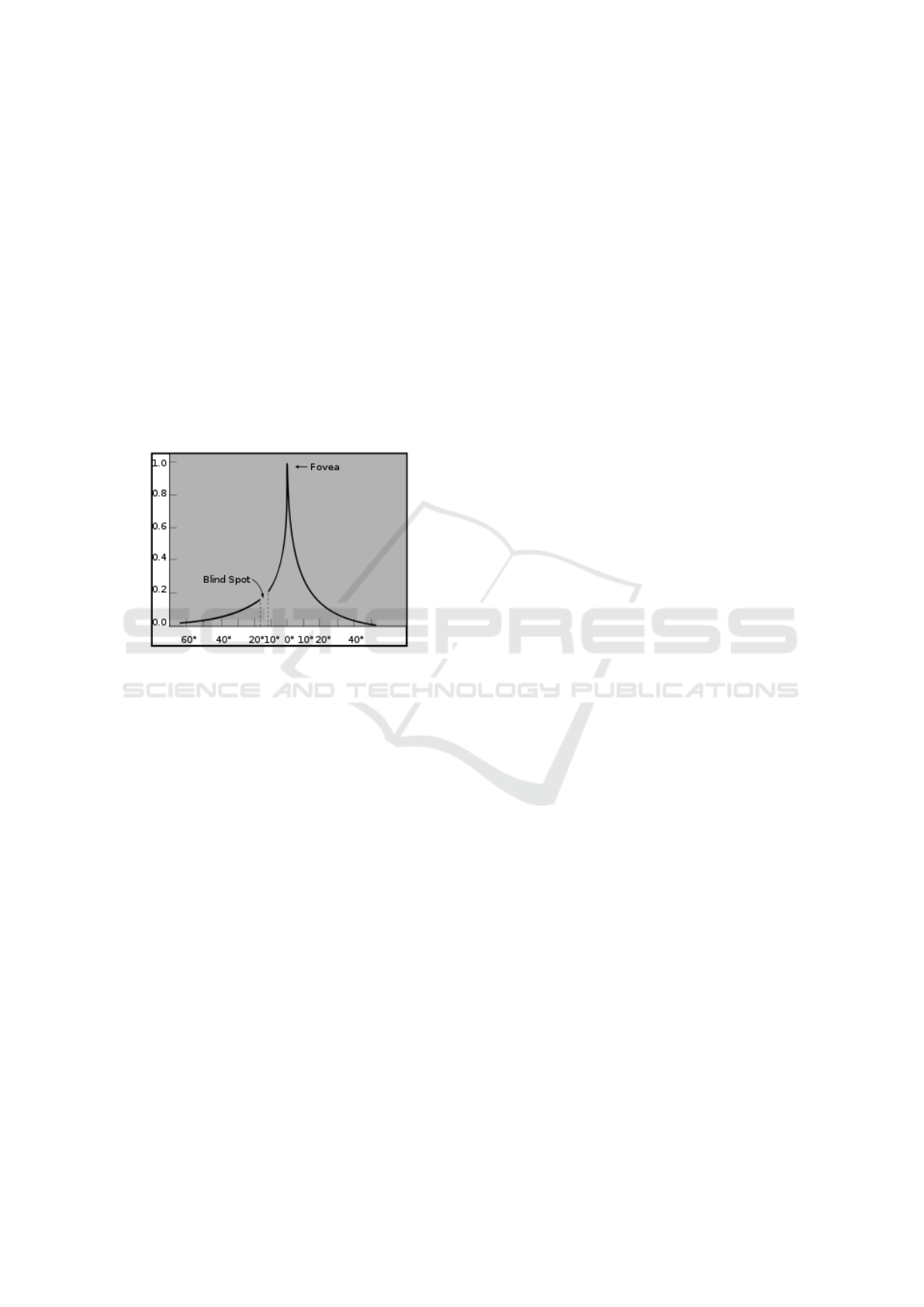
eyes are focused to. As an example, a curve demon-
strating the perceived resolution, proposed by Hun-
ziger (Hunziker, 2006), is shown in Figure 1. This has
stemmed a lot of research interest, and there are mul-
tiple papers from the topic of applying gaze direction
and visual acuity curve to the rendering (Patney et al.,
2016; Spjut et al., 2020; Tursun et al., 2019; Koskela
et al., 2019; Stengel et al., 2016; Guenter et al., 2012;
Meng et al., 2018).
With the above in mind, a rendering system can be
designed so that the rendering quality is not as high at
the peripheral area as it is at the area currently being
looked at, without a human using the system noticing
the difference. The resulting degrees of freedom, lib-
erating us from uniform precision requirements, will
play a key role in our design.
Figure 1: Visual acuity function of the human eye (Hun-
ziker, 2006).
2.2 3D Model Acceleration Structures
For the ray intersection to be efficient the ray data and
the object or bounding volume memory locality is im-
portant. This helps in the throughput of the system
when intersections are being calculated in billions per
second. Initial rays from user’s eye are rather consis-
tent. The reflection rays hitting the surfaces are nearly
random. To ease these challenges, it is common to
have a higher level data structure for the 3D data. A
commonly used approach is a bounding volume hier-
archy (BVH) presented by Kay and Kajiya (Kay and
Kajiya, 1986).
A BVH can be used to define the up-most scene
hierarchy with bounding volumes. Each object in
the hierarchy is bounded with an axis-aligned bound-
ing box (AABB) or with oriented bounding boxes
(OBB) that can be optionally bounded by AABB.
These bounding volumes can form a binary tree data
structure, where each branch has a bounding box that
is spanned over its children. BVH can have different
degrees meaning how many children each node can
have. Good examples from different degrees of BVH
is presented for example by Barringer (Barringer and
Akenine-M
¨
oller, 2014).
2.2.1 Object Intersection
In the above setup, there are various ways rays can in-
tersect objects within the volumes. Below we list the
options we have considered as part of this research.
Abstract Shapes. Intersection of ray and sim-
ple abstract shapes, like AABBs, OBBs and spheres
can be done few simple mathematical operations. For
AABB ray intersection, there are several optimized
algorithms, for example the one shown by Williams
(Williams et al., 2005). OBB intersection is usually
done by transforming the incoming ray to the OBB
space and using then ray AABB intersection.
Triangle Mesh Intersect. Triangle intersection
can use texture data for faster data access. In addi-
tion, complex triangle meshes can be split to multiple
separate AABB blocks. Triangle data can be stored
efficiently by using a single vertex and two edges be-
ing stored in a 1D float texture in a barycentric coor-
dinate system (M
¨
oller and Trumbore, 1997).
Voxel Intersect. Voxels, meaning values on a reg-
ular grid, have many benefits in ray tracing over trian-
gulated mesh used in rasterization. Voxel data struc-
ture can be also hierarchically mipmapped. This can
be done for example averaging eight samples to one
per each resolution step. This helps with the com-
putational resource consumption, because lower res-
olution rays can be sampled using lower resolution
voxel samples, therefore needing less deeper intersec-
tion walk into the octree (Williams, 1983; Meagher,
1980).
2.2.2 DirectX Raytracing
DirectX Raytracing (DXR) (DirectX Raytracing,
2018) enables two level hardware acceleration for ray
intersections: for the ray to object intersection at the
lower level, and ray to BVH intersection where BVH
is created from the objects at the higher level. DXR
uses term Top Level Acceleration Structures (TLAS)
for the BVH structure and a term Bottom Level Ac-
celeration Structures (BLAS) for the object level data.
The object level data can be triangle based mesh data
or custom data defined by the user. TLAS is formed
from the set of bottom level data sets. High-Level
Shading Language (HLSL) can be used for shader
generation, hit, miss logic against the acceleration
structures created.
GRAPP 2021 - 16th International Conference on Computer Graphics Theory and Applications
170
2.3 Lighting Acceleration Structures
For lighting, we wanted to use classical ray tracing
pattern where the first hit and reflection rays hit are
being lit by ambient, diffuse, specular light. To create
more realistic visuals, we are interested in soft shad-
ows. The creation of soft shadows with area lights can
be implemented by sampling the area light with mul-
tiple samples per intersection. With multiple samples,
we can deduce what part of the area light is being oc-
cluded and what part is hitting the intersection.
In addition to soft and hard shadows done with
direct lighting hits, we were interested from global il-
lumination to achieve natural looking results. From
the current research on global illumination the most
suitable option for our case was to use probe based
structure for the light bounces that reduces of amount
of calculations needed to be done for example when
compared to path tracing. There is a good research
paper from the global illumination from Majercik et
al. (Majercik et al., 2019) covering the 3D grid of
probes being used for global illumination where sin-
gle bounce per frame is calculated to achieve infinite
bounces. They call the method as dynamic diffuse
global illumination. This method has benefit of hav-
ing limited and small performance hit but on the neg-
ative side it has lag. Earlier similar light capture has
been described by Greger (Greger et al., 1998). In ad-
dition, short rays can be used for ambient occlusion
to achieve more natural looking results.
2.4 Foveating Mixed Reality Headset
To research the ray tracing on human eye resolution
we needed hardware that is capable to it. As our gad-
get in the experiments, we use the Varjo XR-1 head-
set (Varjo XR-1 Head Mounted Display, 2020). The
headset is capable of running human eye resolution
visuals using two different resolution areas. In total,
the headset has interface with four viewports – two
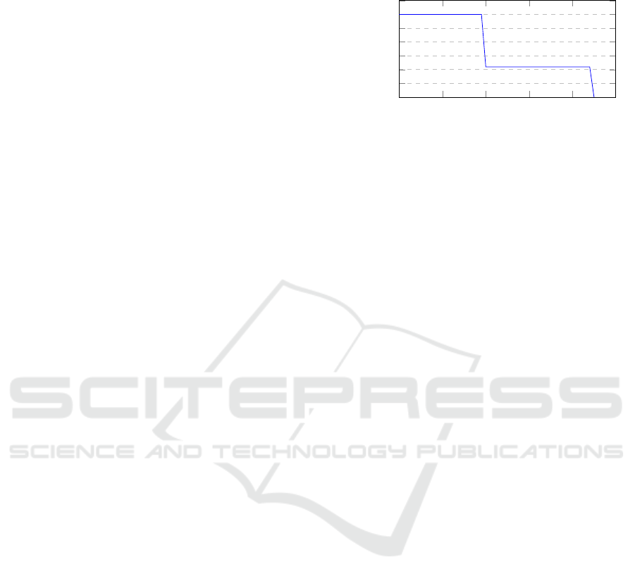
resolution areas for each eye. As visualized in Fig-
ure 2, the higher resolution area is available roughly
40 degrees field of view on x axis (FOVX) having 60
pixels-per-degree (PPD) and a lower one – 22 PPD –
is 90 degrees. The headset has low-latency camera
pipeline to achieve video see through effect. Gaze
tracking follows the eye look-at upto single degree
precision. The tracking system supported is Valve’s
light beacon based system where device sensors are
reading beams from the sensor for the position (Vive
base station, 2020). In addition, an inertial measure-
ment unit is integrated to the device for better orien-
tation accuracy.
0 10 20 30 40
50
0
10
20
30
40
50
60
70
Eccentricity Angle [degrees]
Resolution [pixels-per-degree]
Varjo XR-1 headset resolution
Figure 2: Varjo XR-1 headset resolution areas. High reso-
lution area is used at the center of the FOV and blended to
the low resolution area having larger FOV.
3 IMPLEMENTATION
The ray tracer implementation was custom-made to
be used in research done in this paper. C++ was used
for the scene loading as well as for data structure and
object data creation on the CPU side. DXR APIs were
used to implement the GPU side processing and ren-
dering phases. Varjo software interfaces were used to
draw to the headset displays and to reaad the device’s
pose. Figure 3 presents an example still image from
the headset view for the user.
Next we go through the implementation related
topics. The topics include rendering pipeline (Sub-
section 3.1), managing dynamic resolution (Subsec-
tion 3.2), lights and materials (Subsection 3.3).
3.1 Rendering Pipeline
The rendering pipeline was designed to produce
frames for the headset in real-time frame rates. Figure
4 presents the main phases used to create the frame for
the displays. Below, the phases are discussed in more
detail. We intentionally use rays for all main phases,
like first hits, even if rasterization would most likely
produce better results. The motivation is to have a
simpler and uniform code base for future research.
When starting to create a frame, the most recent
headset pose and gaze direction is read from the track-
ing systems and copied to the GPU side. Object data
changes are applied to the GPU side memory. Any
scene change – such as object or light pose change,
new or deleted objects in scene etc – will invoke the
update of the acceleration structures. Lighting struc-
tures are updated for every frame to achieve infinite
bounces over time. This update means casting rays
from probe, computing one bounce per frame more,
and storing the information to probe’s texture. In ad-
dition, changes in object data, like new data or data
Real-time Human Eye Resolution Ray Tracing in Mixed Reality
171
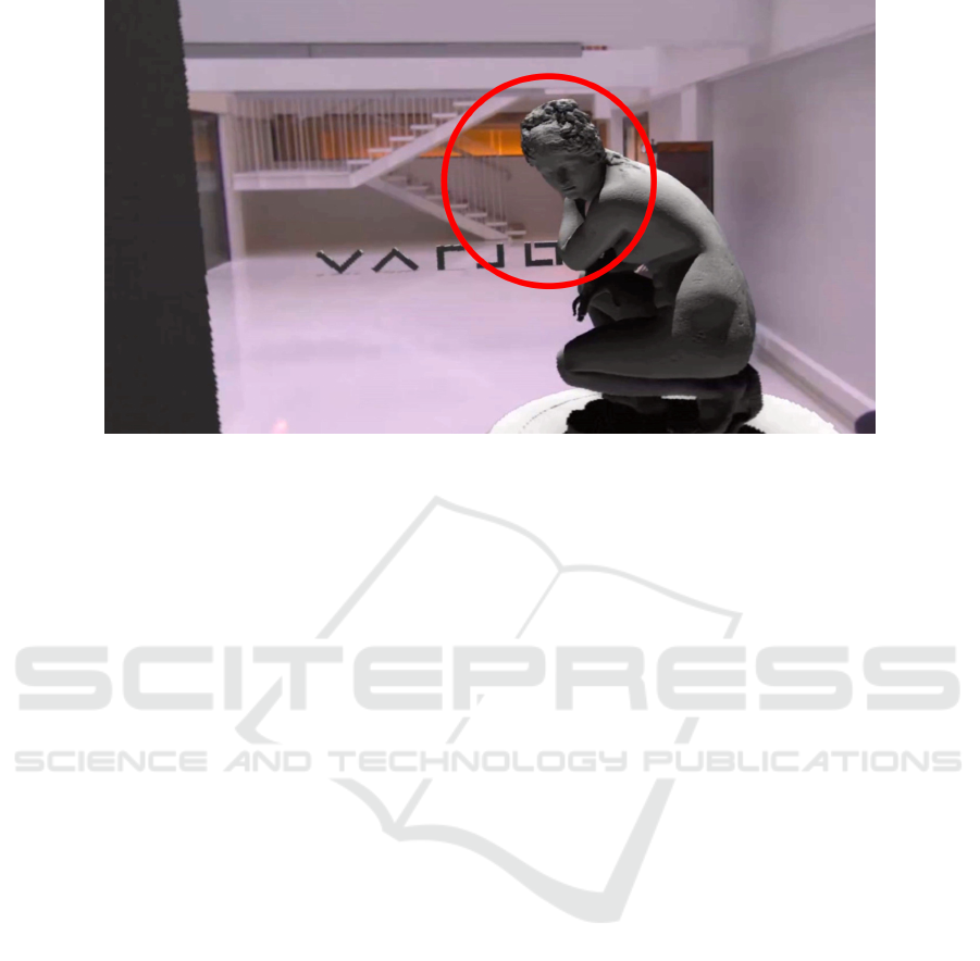
Figure 3: A still image from the left eye while rendering the test scene. For visualisation purposes a red circle for the eye
direction is added. Notice the lower resolution far away from the eye direction. In addition, in the image the shadows from
the virtual objects at the background can be seen at the floor and the statue is being lit also by the bounced light from the floor
and the statue’s stand.
removal, lead to changes in the current GPU memory.
After we have all the latest information at the GPU
side, we can start the actual rendering phases. Ini-
tially, we generate rays to the polar buffer where x-
axis is the distance from the gaze direction and the
y-axis angle counter clockwise from the camera right
vector of the user’s gaze. A falloff mimicking the res-
olution of the human eye is applied as a part of this
operation which be explained in detail at subchapter
3.2. After the rays are generated, we move to first in-
tersections phase. We perform an intersection check
with the BVH and its objects per ray. If a ray in-
tersects an object, we generate lighting calculations
needed for the global illumination. In this phase, we
also store the addition a second intersection ray if the
intersected material had reflection factor.
For the illumination, first light rays are being cal-
culated from intersection point towards the light. If
there are an area light and multiple light rays, the light
ray targets are placed evenly over the target area light
to generate information from the light amount hitting
the intersection. The light rays will contribute to the
color value, if they reach the light. We calculate the
bouncing diffuse light from the probes by sampling
the closest probes per hit and look with short rays the
additional ambient occlusion effect.
The second intersection rays and light rays are cal-
culated in a similar manner as the first ones.
To create the final buffer, we sample the polar
buffer to create the four viewport buffers in Carte-
sian coordinates needed for the head mounted high
and low resolution displays per eye.
This frame is then finally composited top of the
video camera feed from the headset and shown to the
user at the displays. The Varjo software system can
warp the existing frame in low FPS scenarios to re-
orienting the existing frame, like post-rendering 3D
warping addressed by Costella (Costella, 1993) and
adding motion extrapolation similarly to Williams
(Mark et al., 1997). This reorienting and adding of
motion extrapolation is out of the scope of this paper.
3.2 Dynamic Resolution
To reduce computational resource usage we can cre-
ate The visual acuity function can be used to define
the pixel per degree value for a certain eccentricity
angle (Hunziker, 2006; Koskela et al., 2019). For
the resolution related to the angle, we found multiple
different functions behaving adequately for our pur-
poses. In the end, we decided to use the following
function in our implementation that matches well to
the the human eye resolution falloff and the display
system in overall – we can alter still the amount of
pixels used to render the frames to achieve dynamic
resolution:
f (x) = 200/(x + 1), (1)
where x is the eccentricity angle in degrees. The func-
tion produces good results and matches rather well to
the human eye resolution falloff discussed earlier. We
can use this function to define how we generate rays
to polar coordinates. This function gives too many
samples near the look-at area, but works well if the
GRAPP 2021 - 16th International Conference on Computer Graphics Theory and Applications
172
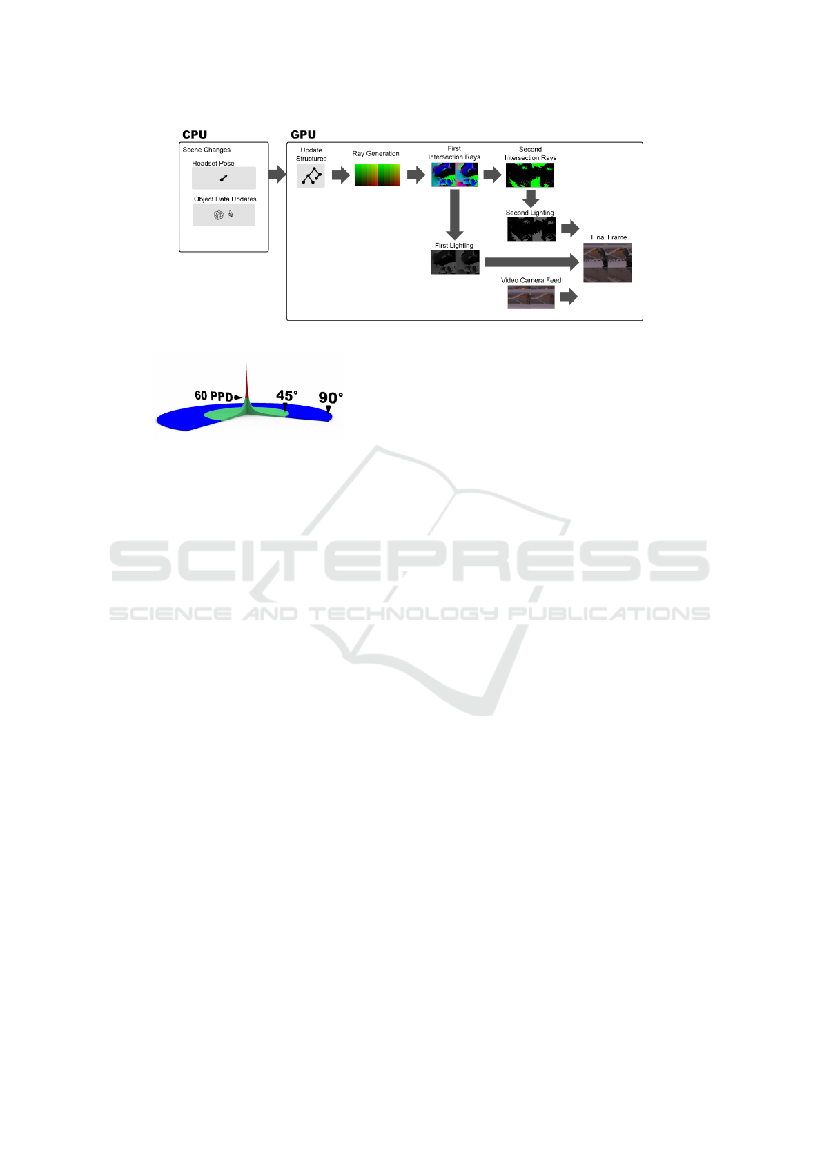
Figure 4: Rendering phases from scene changes to the final frame.
Figure 5: Visual acuity function visualized as 3D volume.
Vertical axis is the PPD value and horizontal axis is the ec-
centricity angle. Base color for the volume is green. Vol-
ume over 60 PPD mark has red color. The volume over 45
degrees is colored as blue.
dynamic resolution is lowered and tackles well the
tolerance and lag in eye tracking. Figure 5 demon-
strates the resulting visual acuity falloff.
Next, we go through an example based on the
above equation. Using integral from this function,
we can see the resolution in radius dimension for the
buffer. For example, when looking at the very center
of displays then from 0 to 45 degrees the resolution
need would be as follows:
f (x) =
Z
45.0
0
200/(x + 1)dx ≈ 765.728
Then, the radius dimension needs at least 766
samples for 45 degree FOV to achieve resolution of
the visual acuity function. Polar buffer texture loca-
tion from current Cartesian buffer texture location can
be calculated with the next equation:
x
polar
= 200 ∗ ln(x
Cartesian
+ 1)
where x is the x location at the texture. The polar
texture location can be turned to radius angle degrees
ρ with next function:
ρ = e
x
polar
/200
− 1
To ensure square sampling of the scene with the
rays, roughly similar height as width used is enough.
Rays used per eye for 90 degree FOV human eye res-
olution can fit to 1024 x 1024 sized data structures.
Figure 6 gives a sample from display buffers used by
the headset. In this image debug polar buffer coloring
can be seen at the background.
To maintain the FPS rate high enough for comfort-
able viewing experience, we made the system to al-
ter the resolution depending on headset pose changes.
This was made by altering the used texture width. The
used width can be changed per frame according to the
needs.
3.3 Lights and Materials
For the lighting visual quality, we implemented
switchable modes to support real-time frame rates
with lower quality and to have better quality with the
cost of frame rate. This feature provides possibility
to have nice soft shadows when looking at something
without large headset pose delta between the frames.
The global illumination uses probes that store irradi-
ance and the distance to geometry to textures. In all
visualizations, materials have diffuse color, specular,
and reflection factors in use. Moreover, area light has
a color and a size in 3D. We use AABBs as the shape
for area light sources.
3.4 Scene Setup
We made two main test scenes to test our implemen-
tation. In Figure 7 we have an image from our gen-
eral test scene. This scene is opened in more detail in
measurements chapter. In Figure 8 we have the visual
quality scene that was used to understand the resolu-
tion curve, texture sizes, and the level of detail (LOD)
levels during the implementation phase of the system.
4 MEASUREMENTS
The headset used at the measurements was Varjo XR-
1. PC used to run the headset has a single Nvidia
GeForce RTX 2080 Ti with NVidia 445.75 drivers,
Real-time Human Eye Resolution Ray Tracing in Mixed Reality
173
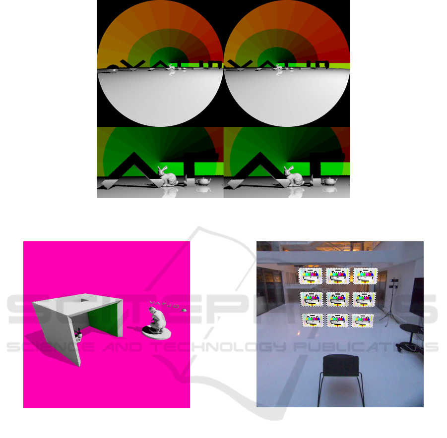
Figure 6: Sample image from the final frame buffer. Viewports showing the foveated rendering low resolution (at top) and
high resolution (at bottom) buffers used for displays on a head mounted display. Background shows polar coordinate debug
coloring having 15 degree tiles.
Figure 7: Mixed reality test scene used for the performance
measurements. Picture is taken so that the camera can over-
see the whole the scene. The pink color is used for visu-
alization purposes for the mixed reality video see through
area. The virtual shadows being cast and captured can be
seen in the image as darkened areas. Test scene fits inside a
2.5 meters tall, 5 meters wide, and 10 meters long bounding
box.
Intel i9-9960X @ 3.1 GHz CPU and Windows 10 op-
erating system. In next subsections we go through the
test scene used, the visual quality of different lighting
settings and the frame creation times measured with
different settings. It is important to note that we ren-
dered full screen content and in mixed reality the ren-
dered content is not usually filling the whole display
area.
Figure 8: Test scene used to understand the resolution
curve, the texture sizes, and LOD levels for models and their
textures. When seated, the test images are filling the whole
field of view.
4.1 Test Setup
We used scene shown in Figure 7 to measure our solu-
tion. The scene has nine triangle based objects, in to-
tal having 290k polygons. All of these triangle based
objects were static in our test scene. We used sin-
gle area light for our measurements that was moving
slowly in a circle path top of the objects. A grid of
lighting probes was placed with even distances over
the whole scene. Total amount of probes placed was
16 x 8 x 16, where 16 x 16 are on horizontal and 8
on vertical axis. Probes were placed with an even dis-
tance in the grid.
To experiment with the lighting, we had possibil-
GRAPP 2021 - 16th International Conference on Computer Graphics Theory and Applications
174
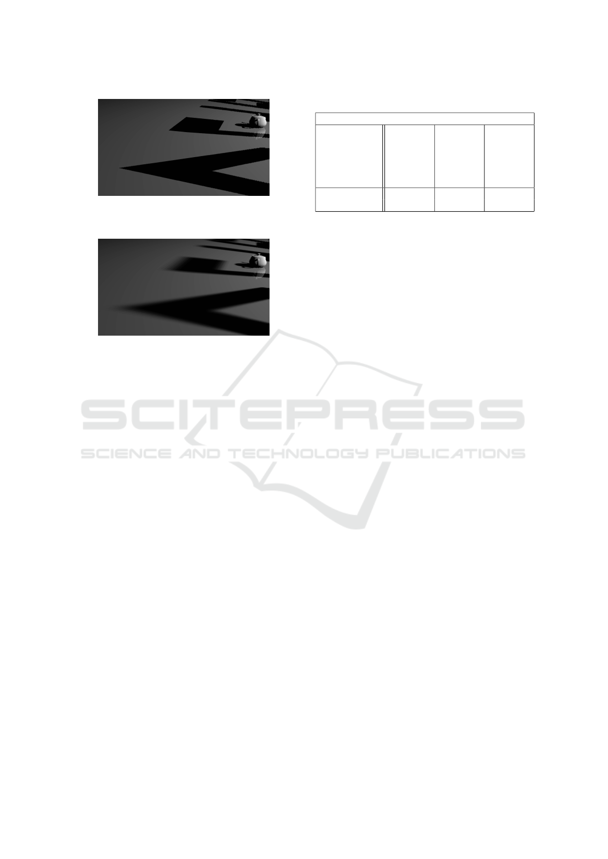
Figure 9: Single area light with 1 sample. Shadows are
hard because single light sample is either hitting or being
occluded.
Figure 10: Single area light with 64 light samples. The
softer shadow can be easily seen when the shadow cast is
further away from partially occluded light.
ity to change the amount of light samples being calcu-
lated. We ended up testing the scene with three differ-
ent amount of samples per intersection. These options
were next: the hard shadows with a single sample,
soft shadows with 64 samples, and soft shadows with
256 samples. Figure 9 shows hard and Figure 10 soft
shadows with 64 samples being used. The final frame
buffer creation used bi-linear interpolation when sam-
pling the polar buffer.
4.2 Frames per Second
To achieve real-time frame rates, the solution should
be able to reach low frame creation times. Especially
in virtual or mixed reality this is crucial to have for
more pleasant experience. We measured the frame
rates by taking an average over ten seconds in our test
scene. We measured the frame-rates with different
fixed resolutions to see the differences more clearly.
In addition, we tested the lighting with two options:
hard and soft shadows. We made test run with dif-
ferent amount of light samples per pixel to under-
stand how complex lighting calculations can be. The
frame rates were basically enough to have real-time
graphics being drawn even with human eye resolution
when low amount of lighting samples are used. With
the more complex lighting setting the rendering speed
was at interactive level only.
Table 1 presents the results measured from 10
second average with the different settings described
Table 1: Performance Measurements.
Average Frame Times
Polar buffer
ray count
including both
eyes [radius
x polar pixel
samples]
Frame
time with
1 light
sample
per Pixel
[ms]
Frame
time with
64 light
samples
per pixel
[ms]
Frame
time with
256 light
samples
per pixel
[ms]
1576 x 768 10.2 35.4 114.8
2048 x 1024 17.2 71.9 199.5
above. When not reaching the maxed out 60 FPS for
Varjo’s interfaces, the rendering speed was bounded
by the ray intersection computations done at the GPU
side. 790MB of GPU memory is used by the applica-
tion. CPU load is under 5 percents and not affecting
to the performance.
5 CONCLUSIONS
In this paper we have presented a ray tracer visual-
ization for head mounted display with 90 degree field
of view that can achieve human eye resolution and
real-time frame rates. The results are encouraging be-
cause they show that it is possible to use ray tracing
purely as the main visualization method – even with
global illumination and scene updates being possible
per frame.
Real-time rendering speed makes it possible to
start consider more naturalistic visualizations espe-
cially in mixed reality situations, where the virtual
and the real world are blended to each other. Exam-
ples from such effect are for example casting lighting
and shadows from reality to another or reflecting or
refracting lights between realities. These effects can
be further enhanced with the real world environment
information, like the shapes and materials.
Future work contains lighting and shadows related
experiments to create more natural visuals between
the realities. In addition, it would be also interest-
ing to combine ray tracing rendering to our earlier re-
search related to multiple simultaneously run mixed
reality applications.
ACKNOWLEDGEMENT
The authors thank the creators of next assets Utah
Teapot (Martin Newell, 1975), Stanford Bunny (Marc
Levoy, Greg Turk, 1994), Vase (Vase, Louvre Mu-
seum, 2016) and Aphrodite statue (Hoang Hiep Vu,
2015). These assets were found to be really useful
during this research work. In addition, authors want
Real-time Human Eye Resolution Ray Tracing in Mixed Reality
175

to thank Ville Miettinen from Varjo from tips related
to the research work during its early days.
REFERENCES
Barringer, R. and Akenine-M
¨
oller, T. (2014). Dynamic
ray stream traversal. ACM Transactions on Graphics
(TOG), 33(4):1–9.
Costella, J. P. (1993). Motion extrapolation at the pixel
level. School of Physics, The University of Melbourne.
DirectX Raytracing (2018).
https://devblogs.microsoft.com/ directx/announcing-
microsoft-directx-raytracing/ Visited May 1, 2020.
Greger, G., Shirley, P., Hubbard, P. M., and Greenberg,
D. P. (1998). The irradiance volume. IEEE Computer
Graphics and Applications, 18(2):32–43.
Guenter, B., Finch, M., Drucker, S., Tan, D., and Snyder, J.
(2012). Foveated 3d graphics. ACM Transactions on
Graphics (TOG), 31(6):1–10.
Hoang Hiep Vu (2015). Aphrodite
crouching, https://sketchfab.com/3d-
models/aphrodite-crouching-at-her-bath-better-
854db6363e0b4957a93f8db4790510ec, licensed
under CC BY 4.0, Visited August 1, 2020.
Hunziker, H.-W. (2006). Im auge des lesers: foveale und
periphere wahrnehmung-vom buchstabieren zur lese-
freude. The Eye of the Reader: Foveal and Periph-
eral Perception-from Letter Recognition to the Joy of
Reading). Zurich: Transmedia.
Kay, T. L. and Kajiya, J. T. (1986). Ray tracing com-
plex scenes. ACM SIGGRAPH computer graphics,
20(4):269–278.
Koskela, M., Lotvonen, A., M
¨
akitalo, M., Kivi, P., Viitanen,
T., and J
¨
a
¨
askel
¨
ainen, P. (2019). Foveated real-time
path tracing in visual-polar space.
Majercik, Z., Guertin, J.-P., Nowrouzezahrai, D., and
McGuire, M. (2019). Dynamic diffuse global illu-
mination with ray-traced irradiance fields. Journal of
Computer Graphics Techniques Vol, 8(2).
Marc Levoy, Greg Turk (1994). Stanford Bunny,
http://graphics.stanford.edu/data/3Dscanrep/, Visited
May 1, 2020.
Mark, W. R., McMillan, L., and Bishop, G. (1997). Post-
rendering 3d warping. In Proceedings of the 1997
symposium on Interactive 3D graphics, pages 7–ff.
Martin Newell (1975). Utah Teapot,
https://graphics.cs.utah.edu/ history/utah teapot.php,
Visited May 1, 2020.
Meagher, D. J. (1980). Octree encoding: A new technique
for the representation, manipulation and display of
arbitrary 3-d objects by computer. Technical report
IPL-TR-80-111, Rensselaer Polytechnic Institute, Im-
age Processing Laboratory, Troy, NY, USA.
Meng, X., Du, R., Zwicker, M., and Varshney, A. (2018).
Kernel foveated rendering. Proceedings of the ACM
on Computer Graphics and Interactive Techniques,
1(1):1–20.
M
¨
oller, T. and Trumbore, B. (1997). Fast, minimum storage
ray-triangle intersection. Journal of graphics tools,
2(1):21–28.
Patney, A., Salvi, M., Kim, J., Kaplanyan, A., Wyman, C.,
Benty, N., Luebke, D., and Lefohn, A. (2016). To-
wards foveated rendering for gaze-tracked virtual real-
ity. ACM Transactions on Graphics (TOG), 35(6):179.
Spjut, J., Boudaoud, B., Kim, J., Greer, T., Albert, R., Sten-
gel, M., Aks¸it, K., and Luebke, D. (2020). Toward
standardized classification of foveated displays. IEEE
Transactions on Visualization and Computer Graph-
ics, 26(5):2126–2134.
Stengel, M., Grogorick, S., Eisemann, M., and Magnor,
M. (2016). Adaptive image-space sampling for gaze-
contingent real-time rendering. In Computer Graph-
ics Forum, volume 35, pages 129–139. Wiley Online
Library.
Tursun, O. T., Arabadzhiyska-Koleva, E., Wernikowski,
M., Mantiuk, R., Seidel, H.-P., Myszkowski, K., and
Didyk, P. (2019). Luminance-contrast-aware foveated
rendering. ACM Transactions on Graphics (TOG),
38(4):1–14.
Varjo XR-1 Head Mounted Display (2020).
http://www.varjo.com/ Visited May 1, 2020.
Vase, Louvre Museum (2016). Ben-
jamin Bardou, https://sketchfab.com/3d-
models/vase-louvre-museum-low-definition-
660fb742a5ff4580862cf5f9eb690d92, Visited August
1, 2020.
Vive base station (2020). https://www.vive.com/ Visited
May 1, 2020.
Williams, A., Barrus, S., Morley, R. K., and Shirley, P.
(2005). An efficient and robust ray-box intersection
algorithm. In ACM SIGGRAPH 2005 Courses.
Williams, L. (1983). Pyramidal parametrics. In Proceedings
of the 10th annual conference on Computer graphics
and interactive techniques, pages 1–11.
GRAPP 2021 - 16th International Conference on Computer Graphics Theory and Applications
176
