
Integration of CAD Models into Game Engines
Bruno Santos
1
, Nelson Rodrigues
1,2
, Pedro Costa
2
and António Coelho
1,3
1
Faculdade de Engenharia da Universidade do Porto, Rua Dr. Roberto Frias s/n,4200-465 Porto, Portugal
2
Abyssal, S.A, Porto, Portugal
3
INESC TEC, Rua Dr. Roberto Frias s/n, 4200-465 Porto, Portugal
Keywords: CAD, Mesh Parameterization, UV Mapping, Boundary First Flattening.
Abstract: Computer-aided design (CAD) and 3D modeling are similar, but they have different functionalities and
applications. CAD is a fundamental tool to create object models, design parts, and create 2D schematics from
3D designed objects that can later be used in manufacturing. Meanwhile, 3D modeling is mostly used in
entertainment, to create meshes for animation and games. When there is the necessity of using real-life object
models in game engines, a conversion process is required to go from CAD to 3D meshes. Converting from
the continuous domain of CAD to the discrete domain of 3D models represents a trade-off between processing
cost and visual accuracy, in order to obtain the best user experience. This work explores different methods for
the creation of meshes and the reduction of the number of polygons used to represent them. Based on these
concepts, an interactive application was created to allow the users to control how the model looks in the game
engine, in a simple way, while also optimizing and simplifying the mapping of textures for the generated
meshes. This application (CADto3D) generates accurate 3D models based on CAD surfaces while giving the
user more control over the final result than other current solutions.
1 INTRODUCTION
One of the main processes when creating a 3D
application with a game engine is asset creation.
However, the 3D objects that are typically displayed
on a game are modeled by designers from scratch,
using specific modeling software. This type of
software gives the user the ability to sculpt objects to
match their needs and artistic vision and with the aim
of performance. On the other hand, CAD models
describe objects that are supposed to be created and
manufactured in real life instead of just being digital.
Thus, these models must ensure the necessary
accuracy for a perfect assembly and to assure the
physical properties. Current tools to integrate CAD
models into game engines mainly rely on file format
conversion. The main objective of this work is to
provide the user with a way to control how the mesh
is created and to provide control of the outcome of the
process, interactively. Also, as a secondary objective
we present the development of a method that can
create texture coordinates automatically for the
generated meshes. Since the created meshes are 3D
objects, while images belong to a two-dimensional
domain, a parameterization process is required to
assign 2D coordinates to 3D vertices. This paper will
explore how this mapping is done to obtain UV
coordinates that minimize both discontinuities and
distortion of the used textures.
In Chapter 2, concepts on mesh simplification and
automatic UV mapping are discussed, and the tools
and libraries available for converting CAD models to
mesh are analyzed. Chapter 3 describes the
methodology used to simplify mesh geometry, how
automatic UV wrapping, and patches
parameterization is manufactured. Chapter 4 is
presented as the application of the proposed
methodology to build a prototype named CADto3D.
Results and comparison with Datasmith are presented
on chapter 5. The last chapter describes the
conclusions and future work.
2 LITERATURE REVIEW
CAD applications store objects by the mathematical
functions that define them. This mathematical
representation allows better accuracy and good
translation into manufacturing. The need for high
fidelity also means that, to analyze and display these,
Santos, B., Rodrigues, N., Costa, P. and Coelho, A.
Integration of CAD Models into Game Engines.
DOI: 10.5220/0010201701530160
In Proceedings of the 16th International Joint Conference on Computer Vision, Imaging and Computer Graphics Theory and Applications (VISIGRAPP 2021) - Volume 1: GRAPP, pages
153-160
ISBN: 978-989-758-488-6
Copyright
c
2021 by SCITEPRESS – Science and Technology Publications, Lda. All rights reserved
153

CAD surfaces, it is preceded a transformation on
these surfaces, from the original continuous domain
into a discrete sampled domain.
Unlike CAD models, Game Engines represent the
objects in a scene using polygonal meshes. The
composition of polygons in a mesh serves as a linear
approximation of their underlying surface (Gregory,
2014). Triangular meshes are widely used because
triangles are automatically convex, planar, and easy
to interpolate, making geometric transformations, and
color and lightning calculations easier (Foley et al.,
1990).
2.1 Tessellation
Triangulation refers to the tessellation of surfaces into
triangles (Gregory, 2014). Triangular meshes are
typically characterized by being unstructured and
having greater freedom in the placement of nodes,
which allows to significantly reduce the number of
vertices used to represent a surface while maintaining
the same accuracy regarding the distance to the
surfaces (Shewchuk, 1999).
There are three different approaches to generating
triangular meshes identified by (Baker, 2005): the
moving/advancing front method (Lo, 1985),
Delaunay based methods (Shewchuk, 2014), and the
Octree approach.
2.2 Mesh Simplification
When generating a mesh, there exists a trade-off
between the number of polygons used and the
performance of the mesh when used in real-time
environments like game engines. This is especially
true when multiple objects are visible at the same
time, meaning some sort of optimization has to be
done in order to increase performance (Low & Tan,
1997).
Frequently, there exist vertices and faces in a
mesh that are visually redundant. When the
underlying mathematical surface of a mesh is known,
this issue can be resolved by re-meshing the surface
with a higher error tolerance. However, when the
mathematical surface is not known, mesh
simplification algorithms have to be applied to try to
obtain a good approximation. These algorithms work
by removing vertices and reconstructing polygons
into larger ones, reducing the geometry used to
represent a mesh while keeping the perceptual
difference between original and simplified at a
minimum (Talton, 2004). Even though these
algorithms tend to be faster than re-meshing, they
introduce irregularities that substantially alter the
topology of the mesh, often in an unpredictable
manner.
2.3 CAD to Geometry Conversion
While the study of surface meshing spans several
decades, the integration of CAD models into game
engines seems to be an under-explored area.
Datasmith (Datasmith, 2020) is a built-in plugin
of Unreal Engine that was first introduced in 2017,
and is currently in beta testing. Datasmith reads many
common CAD file formats, both open formats like
STEP and IGES, but also proprietary formats like the
ones used in CAD applications like SolidWorks and
3ds Max (Datasmith Overview, 2020).
Optim (Theia Optim, 2020) is also an Unreal
Engine plugin by Theia, developed on top of
Datasmith and, like Datasmith, is also in beta (Theia
Optim, 2020). Optim provides visualization tools for
an easier analysis of a generated mesh, displaying
triangle count, distribution and scale, and material
and light lists, among others (Optim Documentation,
2020). It also allows the creation of rules to optimize
imported meshes.
PiXYZ is a company focusing on CAD data, mesh
generation, and optimization (PiXYZ, 2020). They
have two main products related to mesh generation
from CAD files. The PiXYZ Plugin is available for
both Unreal Engine and Unity and works much like
Unreal's Datasmith. The user selects the CAD file,
and what tessellation quality they want. A 3D mesh is
generated and imported into the game engine (PiXYZ
Plugin, 2020). The PiXYZ Studio is a standalone
application that can import CAD files and export the
desired mesh file format. It features tessellation by
parts, hole removal, the decimation of vertices, and
provides repair functions such as removal of
duplicated faces or normal orientation unification
(PiXYZ Studio, 2020).
2.4 Automatic UV Mapping
Meshes are usually defined in three-dimensional
space, while texture images have a two-dimensional
domain. Mesh parameterization is the name given to
the process of calculating and assigning UV
coordinates to vertices of a mesh.
Most parameterization algorithms can only
handle surfaces homeomorphic to a disk. Since CAD
model parts are closed surfaces, it is necessary to
introduce seams when passing the mesh into a 2D
domain representation. This subject causes the
process of UV mapping to have two parts: the
computation of optimal cuts, as so to reduce seam
GRAPP 2021 - 16th International Conference on Computer Graphics Theory and Applications
154

length and discontinuity artifacts, and the
minimization of distortion of triangles of the mesh
mapped onto the plane, as so to reduce distortion
artifacts (Poranne et al., 2017).
More seams result in lower distortion, but too
many seams will result in an inadequate
parameterization with too much discontinuity
(Sorkine et al., 2002). The goal is to optimize
distortion and cuts simultaneously.
2.4.1 Bounded-distortion Piecewise Mesh
Parameterization
The algorithm proposed by (Sorkine et al., 2002)
starts with a random seed triangle. This triangle is
mapped to the plane without any distortion, and
constitutes the initial patch, with its edges being
referred to as the patch front. The algorithm then
examines all of the triangles adjacent to the patch
front, grading each of the "free" vertices of these
triangles (vertices that do not already belong to the
patch) according to multiple criteria such as distortion
of the resulting flattened triangle. New triangles are
then added to the patch iteratively, by selecting the
vertex with the highest grade and mapping it to the
plane, with its "free" neighbours’ grades being
recalculated based on its position. This mapping has
a distortion threshold defined by the user and is
checked for intersections with the patch, as to avoid
overlaps. When there are no more triangles that can
be added to the patch due to the previous constraints,
a new unmapped triangle is selected randomly to start
a new patch, with the algorithm terminating when
there are no more unmapped triangles left.
The distortion measure used is given by the
Jacobian of the transformation function between the
original 3D triangle and its counterpart on the plane.
Other criteria can be added to the distortion measure
like crease angles or the ratio between the patch area
and its squared perimeter, to avoid long, thin patches.
2.4.2 Autocuts
Autocuts (Poranne et al., 2017) tries to parameterize
meshes with minimal distortion and a minimal length
of cuts by optimizing an energy function that takes
into account both measures.
The distortion measure is the symmetric Dirichlet
energy (Smith & Schaefer, 2015), which computes
the Frobenius norm (square root of the sum of the
absolute squares of elements of a matrix) of the
Jacobian of the transformation associated with each
face. The measure that defines a seam (separation of
an edge into two) is given by a monotonic function
that is either 0 if the projection of an edge is
coincident in both faces, or 1 if the distance between
endpoints is different from zero. These measures are
weighted over the area of the faces and length of the
edges, respectively, and are then balanced by a λ
value defined by the user. Autocuts use a homotopy
optimization technique that uses a δ value to control
the smoothness of the function. The initial smoothed
function eliminates many local minima, making
finding a global minimum easier. In each iteration,
the function is sharpened back by reducing the value
of δ, and a local minimum of the new smoothed
function is found by using the previous minimum as
a starting point. This way, this method quickly
converges into an optimal solution.
Besides the unassisted cutting and
parameterization of the mesh, Autocuts also provides
the user with the possibility to interact with how the
UV mapping is done. This feature can be achieved by
tuning the values of the parameters δ and λ, or by
bounding the UV shape to a specific rectangle.
The main limitation of Autocuts is that it does not
guarantee that no global overlaps exist, delegating
that process to the manual interaction by the user.
2.4.3 OptCuts
OptCuts (Li et al., 2018) is an effort to improve on the
solution proposed by Autocuts.
The method introduced by this paper removes the
need for the user to set a λ value to balance face
distortion and seam length, instead of needing a user-
provided distortion bound, for which it minimizes
seam length. OptCuts also has the option to apply
bijectivity constraints to the mapping, removing
overlaps.
OptCuts starts with a bijective UV map created by
Tutte's method, cutting it enough to induce disk
topology if necessary. OptCuts between minimizing
distortion and seam length, updating the
λ value iteratively until the function converges to the
minimum seam length for the distortion bound.
3 METHODOLOGY
The process of having a CAD model as reference and
recreating a similar 3D mesh is manually done by 3D
artists, which is a consuming, costly process and
difficult to achieve with good results when timelines
are shorter. 3D modeling software provides the
designer a finer control over how tessellation is done,
like controlling polygon density in different parts of
the mesh or removing unimportant features.
Integration of CAD Models into Game Engines
155

3.1 Simplification of Geometry
The initial approach taken, regarding the
simplification of geometry, was to select and
implement a mesh decimation algorithm.
Despite their good performance, timewise, the
results obtained when using these algorithms were not
visually satisfactory. Despite being slower, re-
tessellation obtained the best results, as new vertices
are sampled along the surface, which allows the
resulting mesh to better approximate the original
surface, while also maintaining the workflow
associated with it.
3.2 Automatic UV Mapping
The simultaneous optimization of cuts and distortion
in UV mapping is a complex problem. What these
algorithms try to achieve is to minimize objective
metrics such as seam length and distortion. In
practice, this approach often results in "ideal" seams
that do not look as good as the seams defined by a
human designer. Instead of handling the cutting and
parameterization of the mesh at the same time, the
developed method intended to emulate how designers
map UVs: first determine where is the best place to
introduce seams, then calculate the texture
coordinates.
The first step of the developed method is dividing
the mesh into subdivisions, or patches. Since the
CAD models represent parts that had to be
manufactured and assembled, it is normal for there to
be straight angles, in order for everything to fit
together. These natural seams are a good starting
point to begin the patching process, as the
discontinuity of the mapping becomes less noticeable
when the cuts are made alongside these seams. In the
triangular mesh, this criteria for patching means
dividing the surface alongside the edges whose
vertices have multiple normals pointing in different
directions (normal discontinuity).
The patches obtained either have disk topology or
close to it. This is especially useful as it allows the
application of surface parameterization algorithms
directly. The patches that are not homeomorphic to a
disk can generally be categorized into three groups:
surfaces with holes, open surfaces of revolution (e.g.
cylinders and open cones), and the combination of the
first two. The meshes associated with these patches
must be prepared and turned into meshes with disk
topology, to apply a parameterization algorithm. For
the surfaces with holes, the approach is to create a
vertex at the center of the boundary of each hole. This
vertex is then connected to each of the vertices of the
boundary, eliminating the hole. For surfaces of
revolution, the solution is to cut the mesh from one
boundary to the other. This is done by the following
steps:
1. One of the boundaries is identified as stack
0.
2. All the vertices adjacent to the vertices of
stack 0 that are not in stack 0 constitute stack
1.
3. This is repeated until a stack is formed that
has vertices on a boundary.
4. A random vertex from stack 0 is selected and
becomes the first vertex of the cut.
5. The orientation of the mesh between stack 0
and stack 1 is given by the difference
between the centroid of both stacks.
6. The next vertex of the cut is: contained in
stack 1; adjacent to vertex 0; the vertex in
which the edge that connects it to vertex 0
makes the smallest angle with the
orientation of the mesh.
7. This is repeated until the final stack is
reached.
8. The vertices alongside the cut are duplicated
and the faces on one side of the cut are edited
to use these new vertices, this creating a
mesh with disk topology.
This method results in seams that closely follow
the orientation of the mesh.
It is important to notice that finding an edge flow
on a triangular mesh is only possible if the mesh is
tessellated in a regular way, equivalent to a quad
mesh. For irregular meshes the method will produce
sub-optimal results.
Simultaneous cutting and hole-filling is not
supported, which results in unsatisfactory results for
surfaces of revolution with holes. This is because,
even though it is easy to the determine if a vertex is
on a boundary or not, there is no reliable, general way
to determine if that boundary is a hole or the second
outer boundary of the surface.
The ambiguity between what is considered an
outer boundary and what is considered a hole also
affects the decision of how to categorize a surface.
A practical example of this is given by the
comparison between a flat circle with a circular hole
in its center (first surface in Figure 1) and an open
cone (third surface in Figure 1). If the axis of both
surfaces is aligned with the Y axis, and the vertices of
the topmost boundary of the open cone are translated
to Y=0, two similar surfaces are obtained. Therefore,
even though one is an open surface of revolution and
the other is a surface with a hole, they are
homeomorphic to each other. The problem with this
GRAPP 2021 - 16th International Conference on Computer Graphics Theory and Applications
156
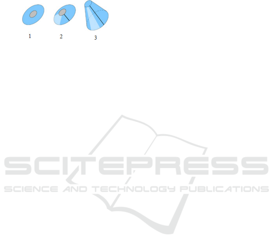
then becomes where alongside the transition, the
surface change from one category to the other (second
surface in Figure 1).
Figure 1: Surface 1 gets hole-filled, surface 3 gets cut, what
about surface 2?
Solutions to this problem could include some
heuristics involving the area of the boundaries, the
number of vertices, or the direction of the normals
alongside them. Instead, the approach taken was to
consider both options as possible for every mesh.
Thus, UV mappings are calculated for both
approaches, as well as the distortion error, with the
final mapping being the one that has the lowest error
value.
3.3 Parameterization
The final step of the process it to parameterize the
obtained patches. The chosen parameterization
algorithm was Boundary First Flattening (Sawhney &
Crane, 2017), because it is fast and generates a
flattening with minimal area distortion and virtually
zero angle distortion. Moreover, because the library
that implements it was simple to integrate. The UV
coordinates generated by the algorithm become the
new UV coordinates of the component.
4 IMPLEMENTATION
The implemented solution is a desktop application
developed using Electron (Electron, 2020).
A Three.js (three.js, 2020) canvas is used inside
of the application, which provides high-level
abstractions for controlling cameras, lights and
interacting with the scene.
Python subprocesses handle the importing, re-
tessellation and exporting of the objects, by using
OpenCascade to import and convert STEP files into
meshes and using the FBX SDK to generate the
output file that can be imported into a game engine.
4.1 UV Coordinates Calculation
The foundation of the developed method to calculate
UVs automatically is the Boundary First Flattening
algorithm implemented in the library geometry-
processing-js (geometry-processing-js, 2020).
The focus of the work done was how to integrate this
library into the project and adapt it, so non-disk
topology objects could have their UVs mapped. The
original mesh of the object is first divided by the
points that have multiple normal vectors with
different orientations. This process is done by starting
a new subset with a random triangle and then
iteratively adding adjacent triangles to it. If the
vertices of the shared edge between a triangle of the
subset and an un-visited triangle have different face
normals, then this un-visited triangle is not added to
the subset. New subsets are created until every
polygon of the mesh belongs to a subset. When the
user paints patches on the main canvas, what is done
is a simple merge of the list of points of both subsets
into a single subset.
Calculating the UVs of a part entails iterating over
every subset of the mesh creating a half-edge mesh
structure for each of them, applying the BFF
algorithm, and packing the obtained UVs into the 0 to
1 range, without overlapping. The application of the
BFF algorithm can be made directly if the subset has
disk topology, or it requires extra preparation. The
process of hole-filling consists of, first, calculating
the longest boundary of the subset. This process is
done by iterating over each of the edges of every
boundary and summing up their length. For every
boundary that is not the longest, a vertex is created in
the polygon soup whose coordinates are the centroid
of the polygon created by the boundary’s vertices.
The half-edge geometry is also altered, with this new
vertex being added and half-edges created between it
and every vertex of the boundary, thereby creating
new faces that eliminate the hole.
The process of cutting the mesh requires finding
its flow. All the vertices adjacent to one boundary are
found, with these vertices constituting a stack. This
process is repeated until a stack has at least one vertex
on a boundary. For each of the stacks, its centroid is
calculated, with the difference between one centroid
and the next being the orientation of the mesh
between those two stacks.
Then, one of the vertices of the first boundary is
selected randomly. The orientation of the plane
created by this vertex, the centroid of the boundary
and the centroid of the next stack, are given by the
cross product of the vectors centroid2-centroid1 and
vertex-centroid1. For every vertex adjacent to this
one on the next stack the same is done, with the next
vertex selected being the one whose cross vector
makes the smallest angle to the previous cross vector.
Integration of CAD Models into Game Engines
157
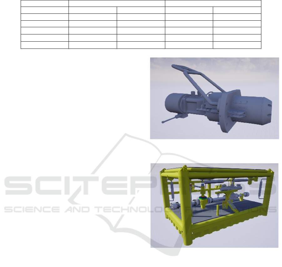
Table 1: Comparison between import times using Datasmith and the developed application using linear deflection of 1.
Ob
j
ect1 Ob
j
ect2
Datasmith CADto3D Datasmith CADto3D
Im
p
ort 70s 75s 340s
Export 5s 25s
Import into Ureal 30s 160s
Total import time 70s 110s failed 525s
Re-tessellation 60s 30s 130s
When a vertex is obtained in each of the stacks, the
cutting process starts. This process is done by basically
duplicating each of the vertices alongside the cut in the
polygon soup, changing the faces on one side of the
cut, on the half-edge mesh, to use these new vertices,
and updating the connectivity of the half-edges, thus
creating one continuous outer boundary.
Both the hole-filling process and the cutting
process are done for each non-disk topology subset,
with the BFF algorithm being applied to the two sets
of polygon soups and half-edge meshes. To decide
what is the best method for the given part, the
quasiconformal error is calculated for both mappings.
The final process of the generation of the UV
coordinates is packing the obtained UV coordinates
into the 0 to 1 UV space, so a single texture file can
be used when applying textures to the object.
5 RESULTS
The focus of the tests was to compare the proposed
solution (CADto3D) with Datasmith to understand if
the former was a viable alternative to the latter. To do
this, the performance of the workflow of both
applications was measured, and the 3D models
created were evaluated for visual fidelity and
geometry complexity.
5.1 Results and Workflow Comparison
with Datasmith
The main workflow of CADto3D is the import of a
STEP file and subsequent export of an FBX. To
evaluate the performance of this process, the models
in Figure 2 and Figure 3 were used, and the time
taken by this process was compared to the import time
of Datasmith on Unreal Engine. The execution time
on Object 1 and Object 2 are given in Table 1.
For smaller files, Datasmith seems to perform well
when importing, compared to the developed
application. This is mainly because CADto3D
requires two import processes (from the STEP file to
the application and from the FBX to Unreal Engine).
Figure 2: Object 1 (STEP file with approximately 230K
entities).
Figure 3: Object 2 (STEP file with approximately 810K
entities).
For larger files, Datasmith does not seem to be very
optimized, and Unreal Engine stopped responding
several times during import, and ultimately failed.
Regarding re-tessellation, the proposed solution
of using temporary files to store shape information
proved to be successful, cutting the time used in fully
re-tessellating a scene in more than half, as opposed
to re-importing with a different linear deflection,
which is what Datasmith does.
Another advantage of CADto3D is that it creates
an FBX file, which does not limit the created mesh to
Unreal Engine, as it can be imported into multiple
applications such as game engines and modeling
software.
GRAPP 2021 - 16th International Conference on Computer Graphics Theory and Applications
158

5.2 Re-tessellation
Besides re-tessellating the object entirely, it is also
possible to re-tessellate a single part or groups of parts
individually, something that cannot be done using
Datasmith.
Tessellation speed is dependent on two factors.
The size and complexity of the shape, that directly
affects the size of the temporary file used to store the
shape information and how much time it takes for the
tessellation to be done. Tessellation quality also
affects tessellation speed, as more vertices and
polygons mean more time transferring the geometry
from the Python process to Three.js and more time
creating the scene.
5.3 UV Calculation
Unlike tessellation, where every part of every model
should be able to be tessellated, not every part can
have its UVs appropriately calculated by the proposed
algorithm in its current state, if at all.
Limitations of the algorithm include continuous
closed surfaces (no normal discontinuities at all),
meshes with complex geometry, surfaces of
revolution with holes, and irregular surfaces of
revolution.
Even though the method proposed produces good
results for many parts some problems were identified:
- Surfaces of revolution that are not straight
produce UVs that have curved boundaries,
which causes grid textures to not line up.
- Dividing by the discontinuities of the
normals often produces good patches but can
also produce too few or too many patches,
limiting the assistance of the user or requiring
them to do too much work joining them.
- Irregularities in the tessellation can lead to
the method not finding the flow of the mesh,
producing bad seams.
- Mapping cylinders with holes in them is
impossible since the algorithm cannot
recognize what is a hole and what is a main
boundary.
6 CONCLUSIONS AND FUTURE
WORK
The application developed can import STEP files,
tessellate models and export FBX files, while
providing a user-friendly interface with available
options for the user to control the characteristics of
the final mesh.
The proposed method to calculate UV coordinates
generates valid maps, with the main contribution in
this step being the preparation process that allows the
application of the BFF algorithm to meshes that do
not have disk topology.
Both the hole-filling method and the cutting
method with detection of mesh flow allow the
generation of UV maps for meshes that generally
could not have BFF applied to them, while still
having acceptable distortion.
6.1 Future Work
In the future, we would like to explore the ability to
import more file types than just STEP. Also, there is
more room for improvement in the developed
application as in the automatic UV method.
The division of the mesh in patches, occasionally
sub or over divides the mesh, which prevents the user
from interacting fully with the subdivisions or
requires too much work to join adjacent patches,
respectively. In situations that not enough patches are
created, a better approach would be to divide the
mesh where normals vary over a certain threshold, in
groups of vertices, instead of just using single vertex
discontinuities. For over-patching, the solution could
be to limit the patch area, relative to object size, or
limit the angle between adjacent patches. Another
solution could be to allow the user to set where the
mesh should be divided by selecting the seam edges
directly.
The other problem is that surfaces of revolution
are cut in sub-optimal ways if they are not tessellated
regularly or have holes in them. To handle irregularly
tessellated meshes, the solution would be to rework
how the flow of the mesh is obtained and develop a
method that can detect edge loops in triangular
meshes, or approximations of these loops since they
not always exist. For surfaces of revolution with
holes, the process would be to identify what is a hole
and what is an outer boundary, applying the hole-
filling technique already defined, and cut the mesh
accordingly.
Finally, since the UV mapping method proposed
often requires user interaction to obtain better results,
an improvement could be the automatic merge of
adjacent patches. This process could either be done
using analytical methods like those in Autocuts and
Optcuts.
Integration of CAD Models into Game Engines
159

ACKNOWLEDGEMENTS
This work was developed under the project POCI-01-
0247-FEDER-024508 - “OceanTech/ Sistema de
Gestão de Operações com base em Veículos
Robóticos Inteligentes para a Exploração do Mar
Global a partir de Portugal”, approved through the
Incentive Scheme R&TD Co-promotion Projects and
co-funded by the European Regional Development
Fund, supported by Portugal2020 through
Compete2020.
REFERENCES
Baker, T. J. (2005). Mesh generation: Art or science?
Progress in Aerospace Sciences, 41(1), 29–63.
https://doi.org/10.1016/j.paerosci.2005.02.002
Datasmith. (2020). Unreal Datasmith | Unreal Engine
Documentation. Retrieved August 12, 2020 from
https://docs.unrealengine.com/en-us/Studio/Datasmith
Datasmith Overview. (2020). Datasmith Overview | Unreal
Engine Documentation. Retrieved August 12, 2020
from https://docs.unrealengine.com/en-
US/Engine/Content/Importing/Datasmith/Overview/in
dex.html
Electron. (2020). Electron | Build cross-platform desktop
apps with JavaScript, HTML, and CSS. Retrieved
August 12, 2020 from https://www.electronjs.org
Foley, J. D., van Dam, A., Feiner, S. K., & Hughes, J. F.
(1990). Computer Graphics: Principles and Practice
(2Nd Ed.). Addison-Wesley Longman Publishing Co.,
Inc.
geometry-processing-js (2020). geometry-processing-js -
fast and flexible framework for 3D geometry
processing. Retrieved August 12, 2020 from
https://geometrycollective.github.io/geometry-
processing-js
Gregory, J. (2014). Game Engine Architecture, Second
Edition (2nd ed.). A. K. Peters, Ltd.
Li, M., Kaufman, D. M., Kim, V. G., Solomon, J., & Sheer,
A. (2018). OptCuts: Joint optimization of surface cuts
and parameterization. SIGGRAPH Asia 2018 Technical
Papers, SIGGRAPH Asia 2018, 37(6).
https://doi.org/10.1145/3272127.3275042
Lo, S. H. (1985). A new mesh generation scheme for
arbitrary planar domains. International Journal for
Numerical Methods in Engineering, 21(8), 1403–1426.
Low, K.-L., & Tan, T.-S. (1997). Model Simplification
Using Vertex-clustering. Proceedings of the 1997
Symposium on Interactive 3D Graphics, 75--ff.
Optim Documentation. (2020). What is Optim. Retrieved
August 12, 2020 from https://docs.theia.io
PiXYZ. (2020). Pixyz | Get your 3D data ready for new
experiences. Retrieved August 17, 2020 from
https://www.pixyz-software.com
PiXYZ Plugin. (2020). PixyzPlugin - The bridge for
connecting 3D data to the gaming world - PiXYZ
Software. Retrieved August 17, 2020 from
https://www.pixyz-software.com/plugin/
PiXYZ Studio. (2020). PixyzStudio - The ultimate 3D
preparation software - PiXYZ Software. Retrieved
August 17, 2020 from https://www.pixyz-
software.com/studio/
Poranne, R., Tarini, M., Huber, S., Panozzo, D., & Sorkine-
Hornung, O. (2017). Autocuts: Simultaneous distortion
and cut optimization for UV mapping. ACM
Transactions on Graphics, 36(6).
https://doi.org/10.1145/3130800.3130845
Sawhney, R., & Crane, K. (2017). Boundary First
Flattening. ACM Trans. Graph., 37(1), 5:1--5:14.
https://doi.org/10.1145/3132705
Shewchuk, J. R. (1999). Lecture Notes on Delaunay Mesh
Generation. Department of Electrical Engineering and
Computer Science, University of California at Berkeley
Shewchuk, J. R. (2014). Reprint of: Delaunay refinement
algorithms for triangular mesh generation.
Computational Geometry: Theory and Applications,
47(7), 741–778.
https://doi.org/10.1016/j.comgeo.2014.02.005
Smith, J., & Schaefer, S. (2015). Bijective Parameterization
with Free Boundaries.
ACM Trans. Graph., 34(4),
70:1--70:9. https://doi.org/10.1145/2766947
Sorkine, O., Cohen-Or, D., Goldenthal, R., & Lischinski,
D. (2002). Bounded-distortion Piecewise Mesh
Parameterization. Proceedings of the Conference on
Visualization ’02, 355–362.
Talton, J. O. (2004). A short survey of mesh simplification
algorithms. University of Illinois at Urbana-
Champaign.
Theia Optim. (2020). OPTIM - Theia Interactive. Retrieved
August 17, 2020 from https://theia.io/optim/
three.js. (2020). three.js – JavaScript 3D library. Retrieved
August 17, 2020 from https://threejs.org.
GRAPP 2021 - 16th International Conference on Computer Graphics Theory and Applications
160
