
BirdSLAM: Monocular Multibody SLAM in Bird’s-eye View
Swapnil Daga
1 a
, Gokul B. Nair
1 b
, Anirudha Ramesh
1 c
, Rahul Sajnani
1 d
,
Junaid Ahmed Ansari
2
and K. Madhava Krishna
1 e
1
Robotics Research Center, KCIS, IIIT Hyderabad, India
2
Embedded Systems and Robotics, TCS Innovation Labs, Kolkata, India
Keywords:
Monocular SLAM, Multibody Simultaneous Localization and Mapping, Bird’s-eye View.
Abstract:
In this paper, we present BirdSLAM, a novel simultaneous localization and mapping (SLAM) system for the
challenging scenario of autonomous driving platforms equipped with only a monocular camera. BirdSLAM
tackles challenges faced by other monocular SLAM systems (such as scale ambiguity in monocular recon-
struction, dynamic object localization, and uncertainty in feature representation) by using an orthographic
(bird’s-eye) view as the configuration space in which localization and mapping are performed. By assum-
ing only the height of the ego-camera above the ground, BirdSLAM leverages single-view metrology cues to
accurately localize the ego-vehicle and all other traffic participants in bird’s-eye view. We demonstrate that
our system outperforms prior work that uses strictly greater information, and highlight the relevance of each
design decision via an ablation analysis.
1 INTRODUCTION
The race to level 5 autonomy is a thrust factor in de-
veloping accurate perception modules for driverless
vehicles. A majority of such industrially-led solu-
tions rely on a suite of sensors such as Lidar, GPS,
IMUs, radars, cameras or different permutations of
such sensors. In this paper, we deviate from this
paradigm and pose a challenging research question:
“How accurately can we estimate the ego motion of
a driving platform and the state of the world around
it, by using only a single (monocular) camera”? In
robotics parlance, this task of estimating the ego-
motion of a “robot” and the state of its environment
is referred to as simultaneous localization and map-
ping (SLAM) (Durrant-Whyte and Bailey, 2006; Bai-
ley and Durrant-Whyte, 2006). A generalization of
the SLAM problem—known as multibody SLAM—is
of interest to us. While a conventional SLAM system
only estimates the robot’s ego-motion and the static
scene map by using the stationary features, multibody
a
https://orcid.org/0000-0003-0674-8602
b
https://orcid.org/0000-0003-4036-1356
c
https://orcid.org/0000-0001-8233-5653
d
https://orcid.org/0000-0001-7714-5855
e
https://orcid.org/0000-0001-7846-7901
SLAM additionally estimates every other actor’s mo-
tion in the scene - hence a generalized system. This is
of paramount importance to autonomous driving plat-
forms, as a precise estimation of the states of other
actors immensely boosts the performance of down-
stream tasks, such as collision avoidance and over-
taking maneuver.
In general, multibody SLAM is ill-posed (i.e.,
does not admit a unique solution family) in mov-
ing monocular camera setup (see Fig. 1). This
is because monocular reconstruction (Mur-Artal and
Tard
´
os, 2017; Engel et al., 2014; Klein and Murray,
2009; Davison et al., 2007) inherently suffers from
scale factor ambiguity. This makes it near-impossible
to recover object trajectories in metric units that can
be directly employed in the downstream tasks men-
tioned earlier. Thus, monocular cameras have so far
found far fewer applications in autonomous driving
stacks. In this work, we move monocular SLAM sys-
tems one step closer to downstream modules.
Conventional monocular SLAM systems (Mur-
Artal et al., 2015; Mur-Artal and Tard
´
os, 2017) de-
tect and track sparse geometric features across input
images and produce a point cloud reconstruction of
the scene. These systems are faced with a plethora
of issues when deployed in scenes with highly dy-
namic actors (e.g., traffic): consistent geometric fea-
Daga, S., Nair, G., Ramesh, A., Sajnani, R., Ansari, J. and Krishna, K.
BirdSLAM: Monocular Multibody SLAM in Bird’s-eye View.
DOI: 10.5220/0010199907110721
In Proceedings of the 16th International Joint Conference on Computer Vision, Imaging and Computer Graphics Theory and Applications (VISIGRAPP 2021) - Volume 5: VISAPP, pages
711-721
ISBN: 978-989-758-488-6
Copyright
c
2021 by SCITEPRESS – Science and Technology Publications, Lda. All rights reserved
711

Figure 1: Top-Left: Illustration of ill-posedness of Multi-
body SLAM. Triangulating a moving object with a moving
camera is impossible as the object has moved away by the
time the second image is captured. Back projected rays in-
tersect at highly erroneous locations. While the car moves
along the yellow line, many possible trajectories (red, ma-
genta) project to the same locations in the image. Bottom-
Left and Right: BirdSLAM operates in orthographic view
overcoming many nuisance factors and making optimiza-
tions simpler, thus convenient to be plugged into down-
stream planners.
ture matches are hard to obtain across vehicles; the
passage of vehicles suddenly obstructs static scene
regions with stable features; the (already ambigu-
ous) scale of reconstruction drifts unexpectedly and
rapidly. Existing approaches tackle some of these
issues by assuming auxiliary inputs such as optical
flow (Ranftl et al., 2016) or depth from stereo cam-
eras (Reddy et al., 2016; Li et al., 2018). Oth-
ers (Costeira and Kanade, 1995; Vidal et al., 2006;
Han and Kanade, 2001) pose the problem as that
of factorizing multiple motions from a 3D trajectory
“soup”. Recent approaches that operate on monoc-
ular cameras are unsuitable for real-time applica-
tions (Nair et al., 2020; Yang and Scherer, 2019).
In this paper, we propose BirdSLAM: a monocu-
lar multibody SLAM system tailored for typical ur-
ban driving scenarios. It operates on an orthographic
view (the bird’s-eye view), where the impact of the
aforementioned “nuisance factors” is low also making
the optimizations simpler as there are less parameters
to operate upon. Further, estimates in orthographic
views can be directly plugged into downstream plan-
ners: a desirable quality (Fig. 1). By assuming that all
relevant “actions” happen on or close to the ground-
plane, and leveraging single-view metrology cues,
BirdSLAM enables scale-unambiguous motion esti-
mation of the ego vehicle and other traffic partici-
pants.
BirdSLAM leverages static features available from
an off the shelf SLAM system (Mur-Artal and Tard
´
os,
2017), dynamic features provided by modern ob-
ject detectors (Chen et al., 2016; Roddick et al.,
2019; Wang et al., 2019), and single-view metrol-
ogy cues (Stein et al., 2003; Song and Chandraker,
2015) to formulate a scale-aware pose-graph opti-
mization problem in bird’s-eye view. This can be
solved using off-the-shelf pose-graph optimization
toolboxes (Grisetti et al., 2011; Agarwal et al., ; Del-
laert, 2012). We demonstrate that BirdSLAM out-
performs existing full 6-DoF SLAM frameworks and
provide an ablation analysis to justify our design
choices.
In summary, BirdSLAM accurately estimates ego-
motion and other vehicle trajectories in bird’s-eye
view over long sequences in real-time, mitigating the
various nuances of traditional 6-DoF SLAM frame-
works for dynamic scenes. We observe that a 3-DoF
SLAM results on an SE(2) representation of real road
plane scenarios compare well with the traditional 6-
DoF SLAM results. This simplifies the optimiza-
tion parameterization thus contributing positively to
reduced runtime as shown in Sec.4.4.5. while not sac-
rificing on the Absolute Translation Error(ATE).
2 RELATED WORK
Traditional Approaches. The traditional ap-
proaches to solving the SLAM problem’s multibody
counterpart are based on separating multiple mo-
tions (Costeira and Kanade, 1995; Fitzgibbon and
Zisserman, 2000; Vidal et al., 2006; Han and Kanade,
2001; Machline et al., 2002) from a given set of
triangulated points. Other traditional approaches
included solving for relative scale for each vehicle
in the scene (Schindler and Suter, 2006; Kundu
et al., 2011; Namdev et al., 2013). The relative scale
reconstruction in most of such approaches is not in
metric scale.
Deep Learning based Approaches. Deep learning
based methods such as Reddy et al. (Reddy et al.,
2016) and Li et al. (Li et al., 2018) leverage the im-
provement in object detection in deep learning ap-
proaches over traditional approaches to improve the
multibody SLAM. However, these two methods use
stereo cameras, thus not facing the problem of scale
ambiguity, which is prevalent in monocular settings.
Recent Approaches. A more recent approach to the
multibody SLAM problem in a monocular setting is
proposed by Nair et al. (Nair et al., 2020) which re-
lies on batch-based pose-graph optimization in 6 DoF.
The optimization framework used in it cannot be ap-
plied in a real-time setting. Another recent framework
VISAPP 2021 - 16th International Conference on Computer Vision Theory and Applications
712

Cubeslam (Yang and Scherer, 2019) uses object rep-
resentations in 6 DoF to improve ego vehicle trajecto-
ries; however, the problem is not cast into a dynamic
setting, and dynamic participant’s trajectories are not
shown explicitly.
3 BIRDSLAM: MULTIBODY
SLAM IN BIRD’s-EYE VIEW
Problem Formulation.
Given a sequence of monocular images I
i
, i ∈ 1 · · · N,
captured from an urban driving platform, with the
camera at height H above the ground, the task of Bird-
SLAM is to estimate:
1. The ego motion of the vehicle X
i
= (x
i
, z
i
, θ
i
) at
each time step, on the ground plane (assumed to
be the XZ plane)
2. An estimate of the motion of all other traffic par-
ticipants X
j
i
= (x
j
i
, z
j
i
, θ
j
i
), j ∈ 1..M
i
, where M
i
is
the number of traffic participants detected in im-
age I
i
.
3. A map M of the environment comprising static
features on the road plane (such as lane markings
etc.).
The overall pipeline of BirdSLAM can be seen in
Fig. 2, where the input images are first passed through
an ego motion estimation pipeline (such as an off-
the-shelf SLAM system). The resulting estimates are
scale-compensated by using single-view metrology
cues. In parallel, traffic participants and static scene
points on the ground plane are mapped to bird’s-eye
view by a pseudolidar representation (Wang et al.,
2019). This constitutes the frontend of BirdSLAM.
The backend of BirdSLAM comprises a novel
multibody pose-graph formulation that employs
constraints of several types (CC: camera-camera,
CV: camera-vehicle, CP: camera-static map point,
VV: vehicle-vehicle) and optimises the pose-graph
in real-time to obtain globally-consistent, scale-
unambiguous multibody SLAM estimates. In the fol-
lowing subsections, we explain each of these compo-
nents in detail.
3.1 BirdSLAM: Frontend
3.1.1 Static Map Initialization
Accurately localizing static features in a scene is
critical to the success of a feature-based monocular
SLAM system. We use ORB features to obtain reli-
able candidate “stable” features, and prune all those
features that do not lie on the road (The “road” region
is found by running a lightweight semantic segmen-
tation network (Rota Bul
`
o et al., 2018) over the input
image). Using the known camera height H, a road
point x
c
p
in image space can be back-projected into the
camera coordinate frame as follows (K ∈ R
3×3
is the
camera intrinsic matrix, and n ∈ R
3
is a unit normal to
the ground-plane (y = 0))
1
:
X
c
p
=
−HK
−1
x
c
p
n
T
K
−1
x
c
p
(1)
3.1.2 Scale-unambiguous Ego-motion
Initialization
We use ego-motion estimates from an off-the-shelf
SLAM system (Mur-Artal and Tard
´
os, 2017) to boot-
strap our system. Typically, such estimates are scale-
ambiguous. However, upon performing the static map
initialization for feature points on road plane using
Eqn. 1, we obtain map points in metric scale (since
the camera height H is known in meters; it resolves
scale-factor ambiguity). We use a moving-median fil-
ter to scale ego-motion estimates to real-world units
(typically meters). This provides us with a reliant ini-
tialisation for ego motion which is used by the pose-
graph as illustrated in Fig. 2 and explained in Sec.
3.3 to feed the camera nodes and edges.
3.1.3 Dynamic Object Localization
Dynamic traffic participants are the root cause of sev-
eral monocular SLAM failures. In BirdSLAM, we
explicitly account (and track!) other vehicles in the
scene to provide state estimates that can be directly
fed to a downstream planning module. In particu-
lar, we employ a monocular depth estimation net-
work (Godard et al., 2018) and compute a pseudolidar
representation (Wang et al., 2019) using the output
depth map. The pseudolidar output is then passed to
a Frustum-PointNet (Qi et al., 2018) to localize vehi-
cles in 3D (see Fig. 3). We back project these vehicles
localized in 3D to bird’s-eye view using Eqn. 1. We
also make use of Eqn. 1 on the bottom-center of 2D
detection of vehicles in the camera frame as a second
unique source of dynamic object localization.
1
Flat-earth assumption: For the scope of this paper,
we assume that the roads are somewhat planar, i.e., no
steep/graded roads on mountains. Consequently, we take
normal vector n = [0, −1, 0] in camera frame according to
KITTI’s (Geiger et al., 2013) conventions where positive
x-axis is in right direction, positive y-axis is in downward
direction and positive z-axis is in forward direction.
BirdSLAM: Monocular Multibody SLAM in Bird’s-eye View
713
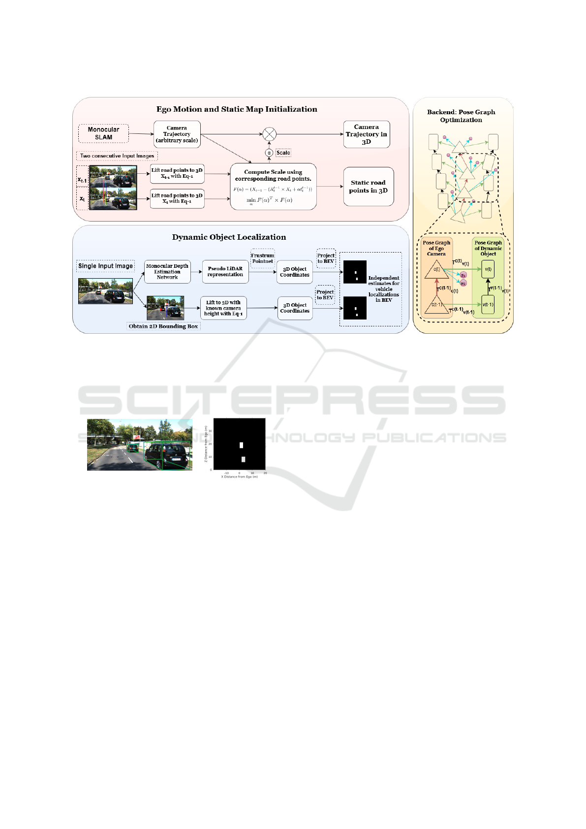
Figure 2: Pipeline: The Ego Motion and Static Map Initialization block illustrates the generation of static road points in
3D, in addition to how we obtain camera trajectory in metric scale. The Dynamic Object Localization block illustrates our
approach to obtain two independent sources of localization of other dynamic objects in frame in Birds-Eye View (BEV).
Detailed explanation, and mathematical representation of these blocks can be found in Sec. 3.1.3. The Backend Pose Graph
Optimization block uses the results obtained from Ego Motion and Static Map Initialization block, and the Dynamic Object
Localization block to create a pose graph as illustrated. In the pose graph formulation, the red, black, green, and blue arrows
show the CC, VV, CV and CP constraints as described in Sec. 3.3.2.
Figure 3: Vehicle Localisation in bird’s-eye view: The left
image shows the 3D bounding box output and the right im-
age shows the tight bounding boxes for the cars we obtain
in bird’s-eye view in camera frame in metric scale from the
procedure described in Sec. 3.1.3. The camera center for the
right image is at (0,0) of XZ plane facing towards positive
Z axis.
The above module is used to initialize our pose-
graph defined in SE(2) in Sec. 4.1.5. For initializa-
tions to our pose-graph in our baselines in SE(3) in
Sec. 4.1.4, we make use of the shape-prior based ap-
proach (Murthy et al., 2017b; Murthy et al., 2017a;
Ansari et al., 2018) for vehicle localizations in the
camera’s coordinate system.
3.2 Generating Amodal Lane Point
Clouds in Camera Frame
We initialize point clouds in the camera frame using
a monocular depth estimation network (Godard et al.,
2018). Using odometry over a window of W frames,
we aggregate sensor observations over time to gener-
ate a more dense and noise-free point cloud. To tackle
noise in monocular depth estimations, we pick points
up to a depth of 5m from the camera and then ag-
gregate depths over a larger window size (≈ 40 − 50
frames) to compensate for its narrow field of view.
This dense point cloud is then projected to an occu-
pancy grid in the bird’s eye view. We use a state-
of-the-art semantic segmentation network (Rota Bul
`
o
et al., 2018) to segment each frame and aggregate
the ”road” and ”lane boundary” prediction point
clouds into separate occupancy grids (see Fig. 4). To
achieve more robustness, we apply additional filter-
ing on both of the above occupancy grids by retaining
only the patches with more foreground cells than a
given threshold in its m × m neighborhood.
We feed these ”road” and ”lane boundary” oc-
cupancy grids into ENet (Paszke et al., 2016) to get
amodal ”road” and ”lane boundary” point clouds in
their respective occupancy grids. The above method
is especially useful when occlusion from dynamic
objects in the scene hinders input data generation.
We further apply morphological post-processing tech-
niques like opening and closing, followed by hough
line transform. We get segregated amodal lane point
VISAPP 2021 - 16th International Conference on Computer Vision Theory and Applications
714
clouds in the camera frame in an occupancy grid for
each monocular image as shown in Fig. 4. These lane
point clouds are used by our SE(2) (Sec. 4.1.5) and
SE(3) approach (Sec. 4.1.4) to fix lateral drifts in the
optimization as explained in Sec. 3.3.2.
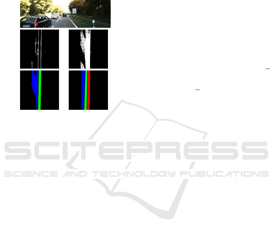
Figure 4: Row 1: A frame in KITTI with 3 lanes, one of
the lanes being occluded due to obstructions. Row 2, Col
1: ”Lane Boundary” occupancy grid pointcloud in bird’s-
eye view. Row 2, Col 2: ”Road” occupancy grid pointcloud
in bird’s-eye view. Row 3, Col 1: Lane Pointcloud output
in bird’s-eye view without ENet. Row 3, Col 2: Amodal
Lane Pointcloud in bird’s-eye view obtained after following
procedure in Sec.3.2.
3.3 BirdSLAM Backend: Pose-Graph
Optimization
We present a lightweight online pose-graph formula-
tion that incorporates constraints from multiple en-
tities in the scene (egovehicle, other vehicles, static
map features). Each of these constraints contributes
a cost-function to the optimization process, which we
explain below.
3.3.1 Cost Function
Following g2o terminologies, the estimate T
W
S
∈ L
characterizes pose for node S in global frame W .
Here, L represents the Lie Group in which the re-
spective transformations are defined which could be
SE(2) or SE(3). The measurement T
S
D
∈ L denotes a
binary-edge from source node S to destination node D
effectively constraining the respective estimates. This
can be represented mathematically as the following
transform:
ϒ
SD
= (T
S
D
)
−1
(T
W
S
)
−1
(T
W
D
) (2)
We also use unary-edges between agent node and
stationary scene-landmarks p located at X
W
p
∈ R
3
in
the global frame W. Here, the agent A could be ego-
camera or the dynamic object in scene. This does not
constrain the orientation of the agent. The resultant
transform between a agent node A with translation
vector tr
W
A
∈ R
3
and a world landmark p in global
frame can be shown as:
Ψ
A
= tr
W
A
− X
W
p
(3)
Our formulation also includes a positive semi-
definite inverse covariance matrix or an information
matrix in each edge’s parameterization, shown as
Ω
E
∈ R
N×N
where N ∈ Z is the number of degrees of
freedom the specific edge E affects. We exploit this
to convey confidence of each constraint. We do so by
scaling Ω
E
upto the effective information matrix Ω
E
by a factor λ ∈ R as:
Ω
E
= λΩ
E
(4)
From the transforms in Eqn. 2 and Eqn. 3, we ob-
tain e
s
∈ R
1×N
by extracting the translation vector di-
rectly, and the yaw angle(for SE(2)) or the axis-angle
rotations(for SE(3)). Given the information matrix
Ω
s
∈ R
N×N
, we obtain the final cost function for ei-
ther a unary or a binary-edge as:
F
s
= (e
s
)(Ω
s
)(e
s
)
T
(5)
3.3.2 Constraints
• Exploiting Dynamic Cues from Vehicles in the
Scene. We categorize our pose-graph into three
sets of relationships denoting camera motion,
vehicle motion and camera-vehicle constraints.
Each of these is obtained as a camera-camera,
vehicle-vehicle and camera-vehicle edge respec-
tively in consecutive time instants t − 1 and t. We
obtain the final constraint for an m vehicle sce-
nario as:
F
D
= F
C(t−1),C(t)
+
m
∑
j=1
F
j
V (t−1),V (t)
+
m
∑
j=1
F
j
C(t−1),V (t−1)
+
m
∑
j=1
F
j
C(t),V (t)
(6)
• Exploiting Static Cues using Landmarks in the
Environment. We also make use of static-cues
from the environment to improve agent motion by
constraining with respect to the lane. We obtain
a dense point-cloud P
l
for the road plane segre-
gated for each lane based on Sec. 3.2. We define
a unary-edge between an agent A(Ego-camera or
BirdSLAM: Monocular Multibody SLAM in Bird’s-eye View
715

vehicle in scene) and each point p on the lane as
shown by Eqn. 3.
F
S
=
∑
p
F
A, p
∀(p ∈ P
l
) (7)
Collectively, the final cost is obtained as the sum
of the above Eqn. 6 and Eqn. 7.
F = F
D
+ F
S
(8)
The scale of the information matrix in Eqn. 4 is
such that higher the scaling(λ), more effective the cor-
responding cost’s observation is going to be. Thus,
edges with relatively more reliable observation are
given higher weights while those that bring in higher
degrees of error are weighed lower. Thus, CC and CP
constraints have the highest weight of 10000 while
VV constraints have the lowest of 1. The weight ini-
tialization provided to CV constraint ranges between
1000 and 10. The applied weight is gauged according
to the depth of the vehicle from the camera. While
pseudolidar (Wang et al., 2019) from Sec. 3.1.3 dom-
inates at lower depths, Eqn. 1 to 2D vehicle detec-
tion bottom-center has an upper hand for far away ob-
jects. If the initial ego-motion initialization from the
off-the-shelf SLAM systems like ORB is erroneous,
the constraints with the stationary points shown above
helps to improve the ego-motion initialization.
4 EXPERIMENTS AND RESULTS
4.0.1 Dataset
We perform experiments over several long KITTI-
Tracking sequences (Geiger et al., 2013). We get
ground truth localization to vehicles from the la-
bels available with the dataset and the ground truth
ego-motion from the GPS/IMU data given with the
dataset.
4.0.2 Error Evaluation
We compute Absolute Translation Error(ATE) as the
root-mean-square of error samples for each vehicle’s
individual frames, including the ego-vehicle in an
SE(2) world. Even though the approaches evaluated
in Table. 1 and Table. 2 perform SLAM in SE(3), we
project their estimated trajectories onto the ground-
plane and compute their error in SE(2) setting for a
fair comparison with the results of Sec. 4.1.5.
4.1 Approaches Evaluated
4.1.1 Nair et al. (Nair et al., 2020):
A monocular multibody approach in SE(3) with a
batch-wise pose-graph optimization formulation that
resolves relationships with dynamic objects as a
means of performing SLAM.
4.1.2 CubeSLAM (Yang and Scherer, 2019):
A monocular approach that unifies 3D object detec-
tions and multi-view object SLAM pipelines in a way
that benefits each other.
4.1.3 Namdev et al. (Namdev et al., 2013):
A monocular multibody VSLAM approach that ob-
tains motion for dynamic objects and ego-camera in
a unified scale. The non tractable relative scale that
exists between the moving object and camera trajec-
tories is resolved by imposing the restriction that the
object motion is locally linear.
4.1.4 Batch Optimized Baseline in SE(3) with
Scale-ambiguous ORB Odometry
A monocular multibody approach in SE(3) similar to
Nair et al. (Nair et al., 2020) but the camera nodes
are fed with scale-ambiguous ORB (Mur-Artal and
Tard
´
os, 2017) initialization. We show that the opti-
mizer itself is able to pull scale-ambiguous odome-
try to metric scale without relying on any prior scale
correction like Sec. 3.1.2. We incorporate stationary
landmarks into this pipeline in the form of a dense
lane point cloud for each lane obtained from Sec. 3.2
applied in a batch version to correct for the lateral drift
contributed to by the relatively erroneous ego-motion
initialization.
4.1.5 Incremental Approach in SE(2) with
Scale-initialized Odometry
A variant of the multibody monocular pose-graph
based optimization pipeline defined in an SE(2)
world. This approach optimizes for multiple objects
in each frame in an incremental manner. There is a
feedback of “optimization results” back as the input
to the optimizer in the next iteration in this approach.
The parameterization of the pose-graph optimizer re-
duces quite considerably in this approach when com-
pared with Sec. 4.1.4 as we now function on a world
governed by 3 degrees of freedom as opposed to 6.
VISAPP 2021 - 16th International Conference on Computer Vision Theory and Applications
716
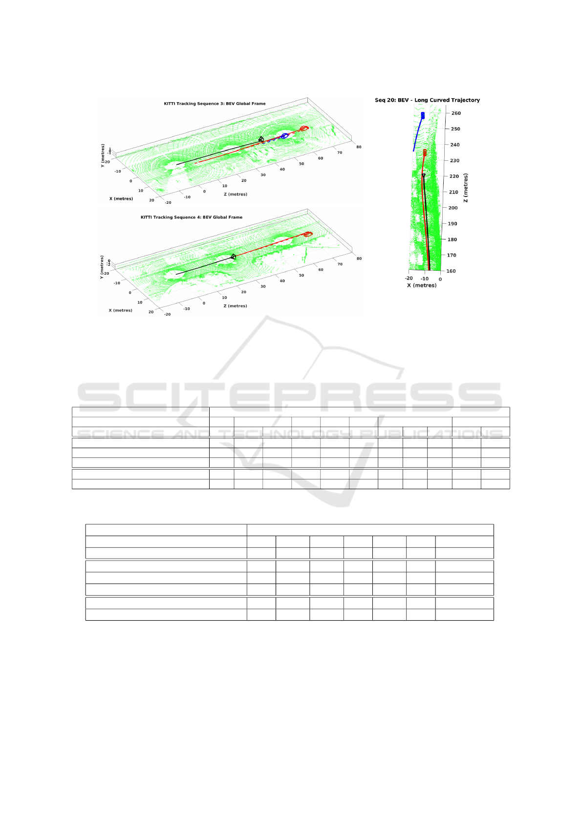
Figure 5: Qualitative Results: Visualizations of ego (black colored camera) trajectories and car object trajectories(red and
blue color) for some of the KITTI sequences, shown along with surrounding lidar points in metric scale. Some of the results
were obtained on very challenging sequences like curved trajectories, occluded detections etc. One such snapshot for a time
instance is shown on the right for sequence 20 which had big turns in its path and some of the tracked cars were far away and
occluded.
Table 1: Absolute Translation Error (in meters) for localised vehicles in scene in bird’s-eye view map, computed as root-
mean-square error across the 2D axes.
Absolute Translation Error (RMS) in Global Frame (meters)
Seq No. 2 3 4 5 10 18 20
Car ID 1 0 1 2 31 0 1 2 3 12 122
Nair et al. (Nair et al., 2020) 5.01 1.61 4.99 2.14 21.64 3.99 1.29 3.45 2.4 9.08 12.86
Namdev et al. (Namdev et al., 2013) 6.35 13.81 11.58 11.18 4.09 10.08 3.77 5.93 3.72 25.19 23.76
Ours Sec. 4.1.4 6.02 2.20 2.24 1.77 1.76 3.99 1.21 2.86 1.23 8.96 13.19
CubeSLAM (Yang and Scherer, 2019) − − − − − − 1.89 2.43 7.17 − −
Ours Sec. 4.1.5 2.09 2.37 2.05 2.34 1.98 3.03 1.6 2.76 1.6 8.61 10.12
Table 2: Absolute Translation Error (in meters) for ego motion in bird’s-eye view map, computed as root-mean-square error
across the 2D axes.
Absolute Translation Error (RMS) in Global Frame (meters)
Seq No. 2 3 4 5 10 18 20
No. of Frames 67 123 149 101 249 141 414
Nair et al. (Nair et al., 2020) 2.30 1.96 6.49 1.60 10.05 2.40 8.85
Namdev et al. (Namdev et al., 2013) 6.24 11.49 11.12 4.08 10.05 3.96 24.38
Ours Sec. 4.1.4 2.05 1.96 1.89 2.22 3.16 2.36 9.05
CubeSLAM (Yang and Scherer, 2019) − − − − − 2.99 −
Ours Sec. 4.1.5 2.25 1.78 6.60 1.58 2.99 1.60 8.81
4.2 Qualitative Results
We obtain accurate localizations to vehicles in the
camera’s view using Sec. 3.1.3. The results have
been illustrated as tight and accurate 3D bounding
boxes obtained to the vehicles in Fig. 3. Fig. 5 il-
lustrates the trajectories obtained after pose-graph op-
timization led to accurate bird’s-eye view mappings
of the ego car and the dynamic vehicles localized in
the scene in a stationary world frame. Despite hav-
ing to cope with a high error contributed to by the
motion model predictor from Sec. 3.1.2, we obtain
BirdSLAM: Monocular Multibody SLAM in Bird’s-eye View
717

close to ground truth bird’s-eye view mapping post-
optimization.
4.3 Quantitative Results
Table. 2 and Table. 1 presents the quantitative per-
formance on a comparative footing for the ego car
and the vehicles localized in the camera’s scene re-
spectively. Our batch-version with scale-ambiguous
odometry initialization showcases a much superior
performance compared with other batch-version, such
as Namdev et al. (Namdev et al., 2013) and Nair et
al. (Nair et al., 2020). Our batch-approach beats them
for all but one vehicle shown in Table. 1. On the
incremental version’s front, we compare our bird’s-
eye view approach with the corresponding baseline
defined in SE(3) as well as CubeSLAM (Yang and
Scherer, 2019), whose errors are computed accord-
ingly after running the codebase released by the re-
spective authors on the particular sequence for which
the input data and the tuned parameters(for that se-
quence) were made available. While the performance
is comparable between the SE(3) as well as the bird’s-
eye view approach, we put ahead a much superior
performance with respect to CubeSLAM (Yang and
Scherer, 2019). This supports the statement that a
bird’s-eye view SLAM approach can potentially per-
form as well as its SE(3) counterpart.
4.4 Ablation Studies on Real-time
Approaches
4.4.1 Contribution by Individual Constraints
We analyze each constraint’s contribution as summa-
rized in Sec. 3.3.2 by computing the final error af-
ter allotting zero weight to individual constraints, ef-
fectively removing its influence on the optimization.
The observations are presented in Table. 3. Since the
CC constraints are given high weight, as explained
in Sec. 3.3.2, the removal of this constraint results
in the deterioration of performance for ego-motion.
It can also be seen that, through the CP constraints,
the stationary points help enhance ego-motion in most
cases. The CV edge that primarily utilizes the pseu-
dolidar (Wang et al., 2019) based localization ensures
that the relation between the ego-motion and all the
vehicles in its scene remains synchronized.
4.4.2 Weight Allotted to Landmark based
Constraints
While it has been established from Sec. 4.4.1 that
static landmarks help improve the absolute transla-
tion error of the trajectory, we analyze as to how
much emphasis must be given to the CP constraint
in terms of the weight. We experiment with various
levels of weights fed to the CP constraint in relation
with that of the CC edge in the formulation. Table. 4
summarizes our observations. While medium weight,
which is equal to that of CC constraints, beats other
modes by a huge margin in a few instances, it com-
petes closely in all the other instances. On the whole,
the performance put forth with medium weight to CP
constraints is superior to the other modes.
4.4.3 Threshold for Landmarks
Since point correspondences and the depth estima-
tions to the same may be more reliable for features
closer to the camera, we place a threshold along Z-
axis of the camera to shortlist landmarks to be con-
sidered in CP constraints as mentioned in Sec. 3.3.2.
Our experiments with various thresholds have been
reported in Table. 4. We find that a threshold T = 20m
contributes optimally to the pose-graph optimization
step.
4.4.4 Impact of Lane Constraints
We show ablation studies on lane-based constrain-
ing of trajectories in our batch-based pose-graph for-
mulation from Sec. 4.1.4. These are performed on
unscaled-ORB initializations. We show that lane-
constraints contribute by with substantial improve-
ment in ATE for almost all vehicles which are experi-
mented with, when compared with the corresponding
ATE before applying lane-based constraints. We sum-
marize our observations in Table. 5.
4.4.5 Runtime Analysis
The incremental optimizer in Sec.4.1.5 takes 0.016s
to solve the pose-graph optimization problem for a
414 frame long sequence as compared to 1.9s for
batch-based approach in Sec.4.1.4. Fig. 6 shows
how a single and multi-object scenario fare in terms
of runtime for each incoming instance. Pose-graph
optimizations (see 3.3) are performed on a quadcore
Intel i7-5500U CPU with 2.40GHz processor. The
frontend involves gathering predictions from multi-
ple neural networks (Godard et al., 2018; Wang et al.,
2019; Qi et al., 2018) and runs at around 33 Hz fre-
quency.
VISAPP 2021 - 16th International Conference on Computer Vision Theory and Applications
718
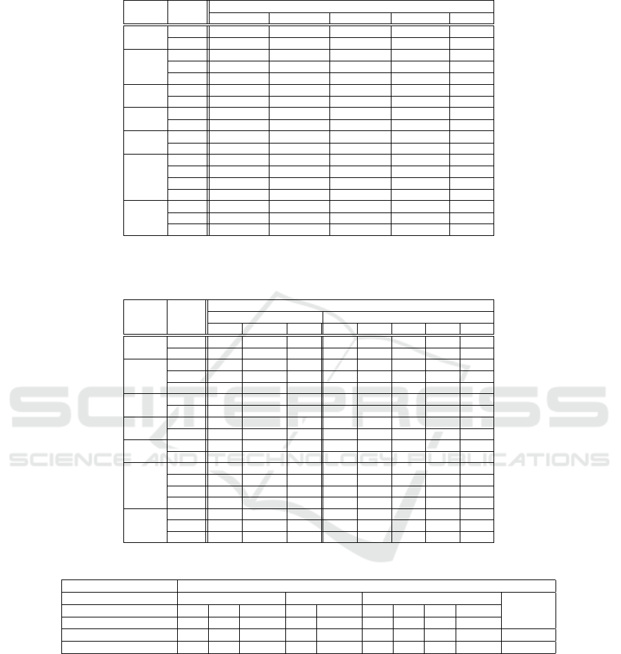
Table 3: Analysis over the contribution of each type of constraint to the final cost.
Seq No. Car ID
Absolute Translation Error (RMS) in Global Frame (meters)
Without CC Without CV Without VV Without CP With all
2
1 3.41 1.96 1.86 1.95 2.09
Ego 2.95 2.25 2.25 2.15 2.25
3
0 2.35 2.40 2.69 2.46 2.37
1 2.74 2.05 2.23 2.12 2.05
Ego 2.73 1.78 1.78 1.96 1.78
4
2 4.52 2.45 2.26 2.58 2.34
Ego 6.82 6.60 6.60 6.42 6.60
5
31 3.43 2.01 1.98 1.98 1.98
Ego 3.05 1.58 1.58 1.57 1.58
10
0 15.72 2.81 2.99 2.98 3.03
Ego 15.43 2.99 3.52 3.00 2.99
18
1 1.27 1.65 1.30 1.50 1.60
2 2.90 2.77 2.84 2.96 2.76
3 1.63 1.82 2.13 1.74 1.60
Ego 2.25 2.21 2.21 2.24 2.21
20
12 12.35 8.75 9.33 8.69 8.61
122 17.65 10.32 10.57 10.09 10.12
Ego 13.85 8.86 8.86 8.88 8.86
Table 4: Performance of the optimiser as a function of weight given to the landmark based constraints relative to the same for
ego motion [column 3 - 5]. Performance of the optimiser with respect to the threshold set for the static feature landmarks on
their depth from the camera [column 6 - 10].
Seq No. Car ID
Absolute Translation Error (RMS) in Global Frame (meters)
Weight to CP Depth Threshold T (m)
Low Medium High 12 15 18 20 ∞
2
1 2.14 2.09 3.15 2.27 2.40 2.14 2.09 2.00
Ego 2.16 2.25 2.82 2.36 2.40 2.32 2.25 2.28
3
0 2.46 2.37 2.35 2.31 2.37 2.31 2.37 2.40
1 2.12 2.05 2.76 2.05 2.10 2.14 2.05 2.07
Ego 1.96 1.78 2.76 1.80 1.82 1.80 1.78 1.87
4
2 2.17 2.34 4.67 2.54 2.34 2.36 2.34 2.26
Ego 6.42 6.60 5.72 6.59 6.42 6.58 6.60 6.45
5
31 1.98 1.98 2.05 1.98 1.98 1.98 1.98 1.90
Ego 1.60 1.58 1.67 1.58 1.57 1.58 1.58 1.60
10
0 2.99 3.03 3.30 3.09 3.11 3.03 3.03 3.18
Ego 2.96 2.99 3.19 3.01 3.00 2.99 2.99 3.07
18
1 1.50 1.60 1.28 1.59 1.59 1.65 1.60 1.68
2 2.96 2.76 2.75 2.91 2.87 2.83 2.76 2.85
3 1.74 1.60 1.80 1.74 1.66 1.62 1.60 1.66
Ego 2.24 2.21 2.15 2.45 2.26 2.25 2.21 2.25
20
12 8.70 8.61 9.38 8.72 8.74 8.68 8.61 8.64
122 10.09 10.12 10.36 10.12 10.10 10.18 10.12 10.17
Ego 8.90 8.86 9.63 8.88 8.90 8.84 8.86 8.85
Table 5: Impact of lane-based constraints on batch-based approach from Sec. 4.1.4.
Absolute Translation Error (RMS) in Global Frame (meters)
Seq No. 3 4 18
Avg ErrorCar ID 0 1 Ego-car 2 Ego-car 1 2 3 Ego-car
Frame length 41 92 123 149 149 62 83 141 141
Before Lane-Constraints 2.91 2.61 2.26 2.15 4.82 1.32 3.22 1.19 2.53 2.56
After Lane-Constraints 2.20 2.24 1.96 1.77 1.89 1.21 2.86 1.23 2.36 1.97
5 CONCLUSION
Multibody SLAM in a moving monocular setup is a
difficult problem to solve given its ill-posedness. In
this paper, we operate in an orthographic (bird’s-eye
view) space to overcome the challenges posed by dy-
namic scenes to the conventional monocular SLAM
systems. Moreover, BirdSLAM operates in real-time
in bird’s-eye view space performing better than cur-
rent real-time state-of-the-art multibody SLAM sys-
tems operating in 6 DoF setup. It also performs at par
with current offline multibody SLAM systems oper-
ating under strictly more resources (time, computa-
tion, features). To the best of our knowledge, Bird-
SLAM is the one of the first such system to demon-
strate a solution to the multibody monocular SLAM
problem in orthographic space. An interesting fu-
ture direction could be to consider cases in which the
BirdSLAM: Monocular Multibody SLAM in Bird’s-eye View
719
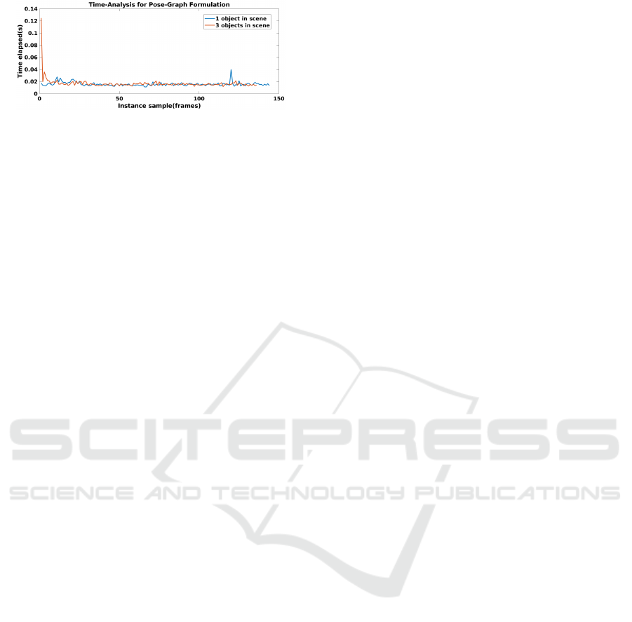
Figure 6: Plot illustrating how number of objects in scene
do not affect the time-elapsed in our optimization formula-
tion from Sec. 3.3.
single-view metrology cues do not hold, such as on
extremely graded/steep roads. Currently, BirdSLAM
accounts for the case where ego-motion initialization
from off-the-shelf SLAM systems like ORB can be
highly erroneous by constraining it with the stationary
cues from the environment. Another potentially inter-
esting work could be to improve the fault-tolerance
of the BirdSLAM system by taking into account the
case when both ego-motion initialization from off-
the-shelf SLAM systems as well as stationary points
in the environment are highly erroneous.
REFERENCES
Agarwal, S., Mierle, K., and Others. Ceres solver. http:
//ceres-solver.org.
Ansari, J. A., Sharma, S., Majumdar, A., Murthy, J. K., and
Krishna, K. M. (2018). The earth ain’t flat: Monocular
reconstruction of vehicles on steep and graded roads
from a moving camera. In IROS.
Bailey, T. and Durrant-Whyte, H. (2006). Simultaneous lo-
calization and mapping (slam): Part ii. IEEE robotics
& automation magazine, 13(3):108–117.
Chen, X., Kundu, K., Zhang, Z., Ma, H., Fidler, S., and
Urtasun, R. (2016). Monocular 3d object detection
for autonomous driving. In CVPR.
Costeira, J. and Kanade, T. (1995). A multi-body factoriza-
tion method for motion analysis. In ICCV.
Davison, A. J., Reid, I. D., Molton, N., and Stasse, O.
(2007). Monoslam: Real-time single camera slam.
IEEE Transactions on Pattern Analysis and Machine
Intelligence.
Dellaert, F. (2012). Factor graphs and gtsam: A hands-
on introduction. Technical report, Georgia Institute
of Technology.
Durrant-Whyte, H. and Bailey, T. (2006). Simultaneous lo-
calization and mapping: part i. IEEE robotics & au-
tomation magazine, 13(2):99–110.
Engel, J., Sch
¨
ops, T., and Cremers, D. (2014). LSD-SLAM:
Large-scale direct monocular SLAM. In ECCV.
Fitzgibbon, A. W. and Zisserman, A. (2000). Multibody
structure and motion: 3-d reconstruction of indepen-
dently moving objects. In ECCV.
Geiger, A., Lenz, P., Stiller, C., and Urtasun, R. (2013).
Vision meets robotics: The kitti dataset. IJRR.
Godard, C., Mac Aodha, O., Firman, M., and Brostow, G.
(2018). Digging into self-supervised monocular depth
estimation. arXiv preprint.
Grisetti, G., K
¨
ummerle, R., Strasdat, H., and Konolige, K.
(2011). g2o: a general framework for (hyper) graph
optimization. In ICRA.
Han, M. and Kanade, T. (2001). Multiple motion scene
reconstruction from uncalibrated views. In ICCV.
Klein, G. and Murray, D. (2009). Parallel tracking and map-
ping on a camera phone. In 2009 8th IEEE Interna-
tional Symposium on Mixed and Augmented Reality,
pages 83–86. IEEE.
Kundu, A., Krishna, K. M., and Jawahar, C. (2011). Real-
time multibody visual slam with a smoothly moving
monocular camera. In ICCV.
Li, P., Qin, T., et al. (2018). Stereo vision-based seman-
tic 3d object and ego-motion tracking for autonomous
driving. In ECCV.
Machline, M., Zelnik-Manor, L., and Irani, M. (2002).
Multi-body segmentation: Revisiting motion consis-
tency. In ECCV Workshop on Vision and Modeling of
Dynamic Scenes.
Mur-Artal, R., Montiel, J. M. M., and Tardos, J. D. (2015).
Orb-slam: a versatile and accurate monocular slam
system. IEEE transactions on robotics, 31(5):1147–
1163.
Mur-Artal, R. and Tard
´
os, J. D. (2017). Orb-slam2: An
open-source slam system for monocular, stereo, and
rgb-d cameras. IEEE Transactions on Robotics.
Murthy, J. K., Krishna, G. S., Chhaya, F., and Krishna,
K. M. (2017a). Reconstructing vehicles from a sin-
gle image: Shape priors for road scene understanding.
In ICRA.
Murthy, J. K., Sharma, S., and Krishna, K. M. (2017b).
Shape priors for real-time monocular object localiza-
tion in dynamic environments. In IROS.
Nair, G. B., Daga, S., Sajnani, R., Ramesh, A., Ansari, J. A.,
and Krishna, K. M. (2020). Multi-object monocular
slam for dynamic environments. arXiv preprint.
Namdev, R., Krishna, K. M., and Jawahar, C. V. (2013).
Multibody vslam with relative scale solution for curvi-
linear motion reconstruction. In ICRA.
Paszke, A., Chaurasia, A., Kim, S., and Culurciello, E.
(2016). Enet: A deep neural network architecture for
real-time semantic segmentation. arXiv preprint.
Qi, C. R., Liu, W., Wu, C., Su, H., and Guibas, L. J. (2018).
Frustum pointnets for 3d object detection from rgb-
d data. In Proceedings of the IEEE Conference on
Computer Vision and Pattern Recognition, pages 918–
927.
Ranftl, R., Vineet, V., Chen, Q., and Koltun, V. (2016).
Dense monocular depth estimation in complex dy-
namic scenes. In CVPR.
Reddy, N. D., Abbasnejad, I., Reddy, S., Mondal, A. K.,
and Devalla, V. (2016). Incremental real-time multi-
body vslam with trajectory optimization using stereo
camera. In IROS.
Roddick, T., Kendall, A., and Cipolla, R. (2019). Ortho-
graphic feature transform for monocular 3d object de-
tection. British Machine Vision Conference.
VISAPP 2021 - 16th International Conference on Computer Vision Theory and Applications
720

Rota Bul
`
o, S., Porzi, L., and Kontschieder, P. (2018).
In-place activated batchnorm for memory-optimized
training of dnns. In CVPR.
Schindler, K. and Suter, D. (2006). Two-view multibody
structure-and-motion with outliers through model se-
lection. PAMI.
Song, S. and Chandraker, M. (2015). Joint sfm and detec-
tion cues for monocular 3d localization in road scenes.
In CVPR.
Stein, G. P., Mano, O., and Shashua, A. (2003). Vision-
based acc with a single camera: bounds on range and
range rate accuracy. In IEEE IV2003 Intelligent Vehi-
cles Symposium. Proceedings (Cat. No. 03TH8683),
pages 120–125. IEEE.
Vidal, R., Ma, Y., Soatto, S., and Sastry, S. (2006). Two-
view multibody structure from motion. IJCV.
Wang, Y., Chao, W.-L., Garg, D., Hariharan, B., Campbell,
M., and Weinberger, K. (2019). Pseudo-lidar from vi-
sual depth estimation: Bridging the gap in 3d object
detection for autonomous driving. In CVPR.
Yang, S. and Scherer, S. (2019). Cubeslam: Monocu-
lar 3-d object slam. IEEE Transactions on Robotics,
35(4):925–938.
BirdSLAM: Monocular Multibody SLAM in Bird’s-eye View
721
