
On Security Analysis of Periodic Systems: Expressiveness and
Complexity
Musab A. Alturki
1,2
, Tajana Ban Kirigin
3
, Max Kanovich
4,5
, Vivek Nigam
6
, Andre Scedrov
7
and Carolyn Talcott
8
1
KFUPM, Dhahran, Saudi Arabia
2
Runtime Verification Inc., U.S.A.
3
Department of Mathematics University of Rijeka, Rijeka, Croatia
4
University College London, London, U.K.
5
National Research University Higher School of Economics, Moscow, Russian Federation
6
fortiss, Munich, Germany
7
University of Pennsylvania, Philadelphia, PA, U.S.A.
8
SRI International, Menlo Park, CA, U.S.A.
clt@csl.sri.com
Keywords:
Formal Methods, Verification, Security, Multiset Rewriting, Industry 4.0, Complexity.
Abstract:
Development of automated technological systems has seen the increase in interconnectivity among its com-
ponents. This includes Internet of Things (IoT) and Industry 4.0 (I4.0) and the underlying communication
between sensors and controllers. This paper is a step toward a formal framework for specifying such systems
and analyzing underlying properties including safety and security. We introduce automata systems (AS) moti-
vated by I4.0 applications. We identify various subclasses of AS that reflect different types of requirements on
I4.0. We investigate the complexity of the problem of functional correctness of these systems as well as their
vulnerability to attacks. We model the presence of various levels of threats to the system by proposing a range
of intruder models, based on the number of actions intruders can use.
1 INTRODUCTION
Technologies such as networked devices including
simple sensors and controllers as well as cyber-
physical systems and Internet of Things (IoT) are be-
ing increasingly adopted in industry to improve pro-
duction efficiency and to enable process agility and
product personalization. This trend is referred to as
Industry 4.0 (I4.0). The combination of flexible in-
terconnectivity and insecure devices also presents op-
portunities for cyber-attacks. In an industrial setting
such attacks lead to serious material or human dam-
age. One example is the attack on a steel mill, requir-
ing the factory to stop its production resulting in great
financial loss (Cyberattack, 2015).
The IEC 61499 international standard for dis-
tributed industrial control systems (Zoitl and Lewis,
2014; Yoong et al., 2015) proposes defining the
functionality of the whole system using a platform-
independent Application model. The model is com-
posed of elements called function blocks (FBs) that
interact via data and event interfaces (Zoitl and Lewis,
2014; Yoong et al., 2015).
There is a number of works carrying out sys-
tematic, but informal security analysis for I4.0 sys-
tems including a recent BSI report on the security of
OPC-UA (machine to machine communication proto-
col for industrial automation) (Fiat et.al., 2017) and
the ENISA study on good practices for IoT secu-
rity (ENISA, 2018).
This paper is a step toward a formal analysis of
I4.0 applications. Our formal framework is based on
Multiset Rewriting (Durgin et al., 2004) (MSR). Mo-
tivated by the requirements of I4.0 applications, we
propose different MSR models:
Automata Systems (AS) are systems similar to those
specified by the IEC 61499 standard. In particular,
FBs are specified as possibly non-deterministic Mealy
machines (Savage, 1998) that interact by carrying out
local computations and exchanging events.
Alturki, M., Kirigin, T., Kanovich, M., Nigam, V., Scedrov, A. and Talcott, C.
On Secur ity Analysis of Periodic Systems: Expressiveness and Complexity.
DOI: 10.5220/0010195100430054
In Proceedings of the 7th International Conference on Information Systems Security and Privacy (ICISSP 2021), pages 43-54
ISBN: 978-989-758-491-6
Copyright
c
2021 by SCITEPRESS – Science and Technology Publications, Lda. All rights reserved
43

Table 1: Summary of complexity results for Functional Correctness Problem (FCP) and Security Problem for Functionally
Correct Systems against Intruders (SP-FCS).
System
Model
FCP SP-FCS SP-FCS with an Intruder using only one action
AS PSPACE-Complete [Th.4.11, Th.4.12] In PSPACE [Th.5.5] PSPACE-Hard [Th.5.5]
PAS PSPACE-Complete [Th.4.11, Th.4.12] In PSPACE [Th.5.5] PSPACE-Hard [Th.5.5]
LAS coNP-Complete [Th.4.13, Th.4.14] In PSPACE [Th.5.5] PSPACE-Hard [Th.5.5]
Periodic Automata Systems (PAS) refine AS by in-
corporating the assumption that I4.0 applications are
periodic. That is, an application carries out a collec-
tion of tasks by execution of its FBs periodically.
Locally Bounded Periodic Automata Systems
(LAS) refine PAS by bounding the number of execu-
tions of each FB withing one system cycle.
We first investigate the complexity of the Func-
tional Correctness Problem (FCP), that is, deciding
whether a system does not lead to a critical configura-
tion that may lead to human or financial losses. FCP
can be seen as checking whether the system behaves
correctly without the presence of an intruder.
When considering an intruder, we follow the find-
ings of the BSI report on OPC-UA security (Fiat et.al.,
2017). The report concludes that message injection
and tampering attacks pose the most serious threats
to I4.0 applications. Following this assessment, we
propose intruder models, inspired by the Dolev-Yao
intruder model (DY) (Dolev and Yao, 1983), where
the intruder controls the network. Our intruders can
inject, tamper and block messages. We also consider
a bounded version of intruders that can only interfere
with the system a bounded number of times.
We then investigate the Security Problem for
Functionally Correct Systems (SP-FCS), that is, de-
termining whether a functionally correct system can
reach a critical configuration in the presence of an in-
truder. Obtained results are summarized in Table 1.
Our computational complexity results refer to stan-
dard complexity classes NP (non-deterministic poly-
nomial time) and PSPACE (polynomial space) (Sav-
age, 1998).
Even with the relatively simple AS model, the
complexity of both problems is PSPACE-complete. A
class of AS, LAS, for which the complexity of FCP
is co-NP-complete is identified. However, the com-
plexity of SP-FCS does not improve, even in the case
when the intruder is allowed to use only one action.
Sections 2 and 3 motivate this work with related
work and an example taken from an I4.0 application.
In Section 4 we introduce AS as a MSR model and
specify various classes of AS. We define FCP prov-
ing complexity results for various AS classes. In Sec-
tion 5, we introduce MSR intruder models and present
complexity results for SP-FCS for different assump-
tions on intruders and types of systems. In Section 6
we present results of SP-FCS experiments obtained
using Maude. We conclude in Section 7 by pointing
to future work. Appendix contains the proofs of the
complexity results.
2 RELATED WORK
Recently, (Lanotte et al., 2020) proposed methods
for the verification of cyber-physical systems, tak-
ing into account their actual physical behavior. In
contrast, our approach does not enter into such de-
tails, but rather only considers an abstract level. This
greatly affects the type of verification that is done.
(Lanotte et al., 2020) uses statistical model check-
ing approaches, while we use a symbolic approach
from (Nigam and Talcott, 2019). That approach com-
bines formal executable specification of I4.0 appli-
cations with a bounded intruder model by means of
rewrite modules in Maude (Clavel et al., 2007). Such
bounded intruder is already capable of causing dam-
age by injecting system messages to be received at
the wrong time, causing safety invariants to be vio-
lated and a bad state to be reached. For an equa-
tionally defined bad state, all attack scenarios can
be enumerated using Maude’s search capability. The
symbolic approach may be combined with abstraction
techniques such as (Nigam and Talcott, 2020). Such
abstraction techniques support the engineering design
workflow using theory transformations. In particu-
lar, given a deployment map from application compo-
nents to devices, one can define a theory transforma-
tion that models execution of the application on the
given set of (networked) devices. Given an enumera-
tion of attacks (message flows) one can further define
a theory transformation that provides a security wrap-
per for each device with policies for signing/signature
checking for just those messages needed to prevent
the attacks (Nigam and Talcott, 2020). This paper
provides a mathematical foundation for the specifica-
tion framework in (Nigam and Talcott, 2019), which
is executable in Maude.
ICISSP 2021 - 7th International Conference on Information Systems Security and Privacy
44

Figure 1: PnP Function Blocks, ctl, vac, and track. The internal states of vac and track are shown in their corresponding boxes
and their transitions are elided. The complete specification of ctl is shown in the finite machine to the right.
3 MOTIVATING EXAMPLE
Figure 1 shows the application architecture of a sim-
ple I4.0 unit, called Pick and Place (PnP)
1
. This is
a common pattern in production lines where an arm
picks up something from one location and places it at
another. In this example there is a conveyor belt that
brings containers to a barrier point, and a source of
caps. The arm moves along a track to the right posi-
tioning over the caps. It turns on its vacuum mecha-
nism to lift a cap and moves along the track to the left
where it is positioned over a container. It turns off the
vacuum and is ready for the next cycle.
The PnP application model consists of three func-
tion blocks: track (controls the movement of the arm);
vac (controls the vacuum on/off state and contains a
sensor for detecting whether the piece has been picked
up); and ctl (coordinates the track and vac FBs). These
FBs communicate according to the links shown in
Figure 1 on the left. The behavior of a FB is spec-
ified by an interactive automata similar to a Mealy
automata. Transitions are guarded by predicates on
incoming signals (called events). When a transition
fires, outgoing events are generated and transformed
into incoming events according to the network links.
The automata for ctl is shown on the right in Fig-
ure 1. From its initial state, Init, ctl sends to itself the
message start to start a new production cycle migrat-
ing to state Ready. It then transitions to LOff state,
representing the system with the arm at the left end
and the vacuum off. It emits a GoR event that instructs
track to move the arm to the right position and confirm
that by an atR event. When an event atR arrives, ctl
transitions to ROff state, denoting that the arm is at
the right and the vacuum is off. It emits VacOn to turn
on the vacuum. The controller proceeds in a similar
fashion taking the cap from the right side to the left,
1
See https://www.youtube.com/watch?v=
Tkcv-mbhYqk starting at 55 seconds for a very small
scale version of the PnP
bringing the cap to the correct position. Then it places
the cap over the cylinder by deactivating the vacuum.
If vac fails to pick a cap, it sends NoVac event to ctl.
In this case, ctl moves to state RNoVac and sends an
event to de-activate vac and move to the left side of
the PnP. This is a typical manufacturing application
where a task is repeated periodically. This is reflected
in the fact that all cycles in the specification of FBs,
include the initial state.
For ensuring the safety of the system, analysis of
the logical behavior of the system is normally carried
out using methods such as Systems Theoretic Pro-
cess Analysis (STPA). The analysis should determine
which are the bad system configurations that should
be avoided as they pose safety hazards.
For example, a safety hazard for the PnP is the
event of a cap falling while being moved. (Imag-
ine instead of putting caps on containers the PnP unit
is placing heavy bricks.) Releasing the piece pre-
maturely could injure someone that is passing by or
damage the factory itself, e.g., damaging the conveyor
belt. This safety hazard is related to the critical con-
figuration where track is in state mvL, vac is in off state
and ctl in ROn or in Init state. That is, ctl has received
the signal that vac has picked the cap, but while mov-
ing to the left, the state of vac is off, indicating that
the cap has been released. One way a bad configu-
ration could be reached is if ctl sends a VacOff event
before the arm is all the way to the left (maybe try-
ing to optimize something). This would constitute an
I4.0 application that is not functionally correct, as it
is possible to reach the critical configuration above.
Additionally, if the application is functionally cor-
rect, we ask if an intruder that is capable of injecting
an event into any one of the links, at any time, can
drive PnP into a critical configuration. The answer
is yes. Indeed, as described in (Nigam and Talcott,
2019), there are four ways in which the intruder can
do this. For example, while the cap is being moved,
the attacker can inject the message VacOff to vac,
causing it to release the cap. Alternatively, attacker
On Security Analysis of Periodic Systems: Expressiveness and Complexity
45

may send the message atL to ctl, although the cap is
still being moved, thus causing the ctl to prematurely
deactivate the vac and release the cap.
4 FORMAL MODEL
We briefly review MSR (Kanovich et al., 2014) which
is the language we use to specify systems and in-
truders. Assume a finite first-order typed alphabet,
Σ, with variables, constants, function and predicate
symbols. Terms and facts are constructed by apply-
ing symbols with correct type. For instance, if P is a
predicate of type τ
1
×τ
2
×··· ×τ
n
→ o, where o is the
type for propositions, and u
1
,. ..,u
n
are terms of types
τ
1
,. ..,τ
n
, respectively, then P(u
1
,. ..,u
n
) is a fact. A
configuration is a multiset of ground facts.
Actions are multiset rewrite rules:
W
1
,. ..,W
k
,F
1
,. ..,F
n
−→ W
1
,. ..,W
k
,Q
1
,. ..Q
m
used to change configurations, i.e., model processes.
Facts W
1
,. .., W
k
are preserved by the above rule,
while facts F
1
,. ..,F
n
are replaced by Q
1
,. ..,Q
m
. All
free variables appearing in the post-condition must
appear in the pre-condition. A rule of the form W −→
W
0
can be applied to a configuration S if there is
a subset S
0
⊆ S and a matching substitution θ, such
that S
0
= W θ. The configuration resulting from the
application of this rule to S is (S \S
0
)∪ (W
0
θ). (Sub-
stitution application (Sθ) is defined by mapping term
variables to terms.)
Definition 4.1 (Trace). A trace of MSR rules R is a
sequence of configurations:
S
0
−→
r
1
S
1
−→
r
2
·· · −→
r
n
S
n
−→
r
n+1
.. .
or its finite prefix, such that for all 0 ≤ i, S
i+1
is a
configuration obtained by applying r
i+1
∈ R to S
i
.
Reachability problems are reduced to the exis-
tence of traces over given rules from some initial
to some specified configuration. Since reachability
problems are undecidable in general (Kanovich et al.,
2011), some restrictions are imposed in order to ob-
tain decidability. In particular, we only use MSR
systems with balanced rules, i.e., rules for which
the number of facts in its pre-condition and in its
post-condition is the same. Systems containing only
balanced rules represent an important class of bal-
anced systems, for which several reachability prob-
lems have been shown decidable (Kanovich et al.,
2011; Kanovich et al., 2014; Kanovich et al., 2017).
Our MSR systems representing I4.0 application
and intruders are balanced, denoting a fixed setting
of function blocks communicating using a fixed set of
signals through a network of a fixed capacity.
4.1 Industry 4.0 Specifications
We now present how systems described in Section 3,
are specified as formal MSR models. We use the sig-
nature containing a finite number of constants denot-
ing signals, constants denoting automata states, pred-
icates denoting states of each automaton, and predi-
cates used to denote channels, respectively.
We define automata systems representing a net-
work of FBs which are conceived of as the event-
driven finite automata A
1
, A
2
, . . . , A
`
. Some of the
automata, say A and B, can directly interact through
a channel on which A has the write access and B has
the read/consume access. We denote such a channel
with the predicate R
A,B
. Given a channel R
A,B
, the fact
R
A,B
(m) denotes that, via R
A,B
, A provides an event-
driven signal m to be consumed in some moment by
the intended recipient B, while R
A,B
(∗) denotes that
the channel is empty. An interpretation is that R
A,B
is
a one-cell buffer that may contain a “signal”.
Definition 4.2 (Automata System). An au-
tomata system (AS) is a pair N = (A,R ), where
A = {A
1
,. ..,A
n
} is a finite set of automata and R a
finite set of channels R
A
i
,A
j
from A
i
to A
j
, A
i
,A
j
∈ A,
such that for any pair of channels R
A
i
,A
j
,R
A
l
,A
k
∈ R
if R
A
i
,A
j
= R
A
l
,A
k
, then i = l and j = k.
An automaton A of AS N = (A,R ) is a tuple
(S
A
,q
0
,M
A
,X
A
), where S
A
is a finite set of automa-
ton states with an initial state q
0
∈ S
A
, M
A
a finite set
of message symbols not containing the ∗ symbol, and
X
A
a finite set of instructions of the form:
Q
A
(q), R
B
1
,A
(m
1
),.. . ,R
B
k
,A
(m
k
), R
A,C
1
(∗),... ,R
A,C
`
(∗) −→
Q
A
(q
0
), R
B
1
,A
(∗),... ,R
B
k
,A
(∗), R
A,C
1
(m
0
1
),.. . , R
A,C
`
(m
0
`
)
(1)
where m
1
,. ..,m
k
,m
0
1
,. ..,m
0
`
∈ M
A
, and q,q
0
∈ S
A
.
Automata in an AS communicate by exchanging a
fixed set of (atomic) signals through a fixed number of
distinct channels. Each of the automaton A is defined
by a finite set of balanced rules representing how the
received event signals prompt automata to action. We
refer to all instructions of automata in N = (A,R ) as
system rules X
N
, that is X
N
=
S
A∈A
X
A
.
As per rule Eq. (1), when each of the chan-
nels R
A,C
j
is free, automaton A being in the state q,
getting the signals m
i
via channels R
B
i
,A
, respectively,
moves to its state q
0
, provides the signals m
0
j
via chan-
nels R
A,C
j
, respectively, and in the process discharges
the signals m
j
, freeing all channels R
B
i
,A
. In the spe-
cial case when k = 0, rule Eq. (1) denotes automaton
action prompted internally, only by automaton state.
For an example, consider the PnP system illus-
trated in Figure 1 and the corresponding rules given
in Figure 2. Within this system, the instruction c
3
de-
notes the following action of ctl automata: Being in
ICISSP 2021 - 7th International Conference on Information Systems Security and Privacy
46

ctl c
1
: Q
ctl
(Init), R
ctl,ctl
(∗) → Q
ctl
(Ready), R
ctl,ctl
(start)
c
2
: Q
ctl
(Ready), R
ctl,ctl
(start), R
ctl,track
(∗) →
Q
ctl
(LOff), R
ctl,ctl
(∗), R
ctl,track
(GoR)
c
3
: Q
ctl
(LOff), R
track,ctl
(atR), R
ctl,vac
(∗) →
Q
ctl
(ROff), R
track,ctl
(∗), R
ctl,vac
(VacOn)
c
4
: Q
ctl
(ROff), R
vac,ctl
(HasVac), R
ctl,track
(∗) →
Q
ctl
(ROn), R
vac,ctl
(∗), R
ctl,track
(GoL)
c
5
: Q
ctl
(ROn), R
track,ctl
(atL), R
ctl,vac
(∗) →
Q
ctl
(Init), R
track,ctl
(∗), R
ctl,vac
(VacOff)
c
6
: Q
ctl
(ROff), R
vac,ctl
(NoVac), R
ctl,track
(∗), R
ctl,vac
(∗) →
Q
ctl
(RNoVac), R
vac,ctl
(∗), R
ctl,track
(GoL), R
ctl,vac
(VacOff)
c
7
: Q
ctl
(RNoVac), R
track,ctl
(atL), R
ctl,ctl
(∗) →
Q
ctl
(Init), R
track,ctl
(∗), R
ctl,ctl
(start)
track t
1
: Q
track
(L), R
ctl,track
(GoR) → Q
track
(mvR), R
ctl,track
(∗)
t
2
: Q
track
(mvR), R
track,ctl
(∗) → Q
track
(R), R
track,ctl
(atR)
t
3
: Q
track
(R), R
ctl,track
(GoL) → Q
track
(mvL), R
ctl,track
(∗)
t
4
: Q
track
(mvL), R
track,ctl
(∗) → Q
track
(L), R
track,ctl
(atL)
vac v
1
: Q
vac
(off), R
ctl,vac
(VacOn), R
vac,ctl
(∗) →
Q
vac
(on), R
ctl,vac
(∗), R
vac,ctl
(HasVac)
v
2
: Q
vac
(off), R
ctl,vac
(VacOn), R
vac,ctl
(∗) →
Q
vac
(on), R
ctl,vac
(∗), R
vac,ctl
(NoVac)
v
3
: Q
vac
(on), R
ctl,vac
(VacOff), R
vac,ctl
(∗) →
Q
vac
(off), R
ctl,vac
(∗), R
vac,ctl
(∗)
Figure 2: Instructions of PnP AS.
the state LOff and getting the signal atR denoting that
the arm is in the right-most position, ctl sends the sig-
nal VacOn to engage the vacuuming action with the
vacuum device. Rules c
1
,c
2
,c
3
,c
4
,c
5
formalize one
cycle of the automaton ctl, while rules c
1
,c
2
,c
3
,c
6
,c
7
formalize the other cycle illustrated in Figure 1.
Definition 4.3 (System Configuration). Given an AS
N = (A,R ), a system configuration of N is a mul-
tiset of facts containing exactly one fact Q
A
i
(q), for
each A
i
∈ A, where q ∈ S
A
i
, and exactly one fact
R
A
i
,A
j
(m), for each R
A
i
,A
j
∈ R , where m ∈ M
A
i
.
A system configuration represents a snapshot of
the AS, containing the current states of all automata
and the contents of the connecting channels. No-
tice that, since exactly one of each channel predicates
R
A
i
,A
j
is included, we model systems with at most one
channel from one automata in the system to another,
each channel of a single buffer capacity.
The assumption of single buffer capacity normally
appears in many I4.0 applications, in particular, for
(parts of) applications that require high performance
or are safety critical (Ademaj et al., 2019). This is im-
plemented by using message delivery schedules, such
as those in Time Sensitive Networks, so that only a
single message is received and processed at a time. It
is possible, however, to extend our model so that mul-
tiple channels and larger network capacities can be
represented, e.g., by using multiple R
A,B
facts in the
configuration or by using special facts denoting net-
work bandwidth. However, the implications of such
extensions on the complexity is left for future work.
Definition 4.4 (Initial Configuration). Initial config-
uration of an AS N = (A,R ) is the system configu-
ration of N with one Q
A
i
(q
i
0
) fact, for each A
i
∈ A,
where q
i
0
is the initial state of A
i
, and one fact
R
A
i
,A
j
(∗) for each channel R
A
i
,A
j
∈ R .
Definition 4.5 (Critical Configuration). Given an AS,
we assume a set of system configurations called crit-
ical configurations. We also assume the existence of
a polynomial time algorithm C that recognizes which
system configuration is critical and which is not.
Critical configurations denote bad overall config-
uration of the system. For example, for the system
illustrated in Figure 1, it may be critical that the vac-
uum switches off while the arm is moving left, car-
rying a cap. Then, any configuration containing ei-
ther the facts {Q
vac
(off), Q
track
(mvL), Q
ctl
(ROn)} or
{Q
vac
(off), Q
track
(mvL), Q
ctl
(Init)} would be critical.
We assume that each AS has an associated specifi-
cation of critical configurations. Such configurations
represent situations that are undesired w.r.t. function-
ality of the I4.0 application being modelled by the AS.
Given that I4.0 applications are written as Mealy
machines, one could question the motivation of using
MSR models. One reason is that it is straightforward
to add intruder models as we describe in Section 5
and define the corresponding verification problems.
Mealy machines are not suitable for specifying intrud-
ers that can send messages at any time in any one of
the channels. Another reason is that MSR rules are
more general and can be used to express further fea-
tures, such as nonces used in protocol security, that
are not available in Mealy machines. While nonces
and cryptographic protocols, in general, are not used
in this paper, our models can easily be extended to
formalize e.g., signed messages.
4.1.1 Periodic Automata Systems
We introduce subclasses of AS by incorporating fur-
ther requirements of I4.0. A typical I4.0 application
is periodic, that is, a collection of tasks are repeated
over and over again. For example, the PnP described
in Section 3, repeats the task of placing a cap over a
cylinder. In I4.0 terminology, FBs operate in micro-
cycles, where each automaton repeats one of its cy-
cles, while the whole application operates in hyper-
cycles, which start and end in a system configuration
where all FBs are in their initial states.
Definition 4.6 (Hyper-Cycle). Let N = (A,R ) be
an AS. A hyper-cycle of N is a trace of sytem rules
X
N
, S
0
−→
r
1
S
1
−→
r
2
·· · −→
r
n
S
n
, n ≥ 1, where
S
I
is the initial configuration of N , S
0
= S
n
= S
I
,
S
i
6= S
I
, and S
i
6= S
j
, ∀i, j ∈ {1, .. .n − 1}.
On Security Analysis of Periodic Systems: Expressiveness and Complexity
47

To model periodic behavior, we introduce a class
of systems called Periodic Automata Systems (PAS)
which imposes constraints on the system behaviour.
Definition 4.7 (Periodic Automata System). An AS
N is periodic (PAS) if any finite trace of N starting
from the initial configuration of N is a prefix of an
infinite trace, and any infinite trace of N starting from
the initial configuration of N is the concatenation of
its hyper-cyles.
For example, the PnP in Figure 1 is a PAS. In par-
ticular, ctl may run in two different cycles through its
initial state Init, the outer one and the inner one.
Proposition 4.8. Given a PAS, a system configuration
is reachable from an initial configuration if and only
if it is reachable within one hyper-cycle.
In a PAS the number of applications of instruc-
tions within any hyper-cycle of any automaton could
in principle be exponential. On the other hand, no-
tice that in the PnP example in Figure 1 each of the
instructions is applied at most once in a hyper-cycle.
Definition 4.9 (Locally Bounded Periodic Au-
tomata System). A PAS N = (A,R ), where
A = {A
1
,. ..,A
n
}, is k-bounded if the number of
applications of instructions of any A
i
within a hyper-
cycle of N is at most k. A PAS is locally bounded
(LAS) if it is k-bounded for some explicitly given k.
4.2 Functional Correctness
Functional correctness is an unreachability problem
with critical configurations specified over states of
FBs, denoting bad configurations of the system.
Definition 4.10 (Functional Correctness (FCP)). An
automata system N is said to be functionally correct
if there is no trace of N leading from the initial con-
figuration of N to a critical configuration.
FCP is a safety property for AS. Functionally cor-
rect systems guarantee correct execution of the work-
ing process, within the closed system with no outside
interference. However, this does not guarantee secu-
rity, as intruder actions may lead to undesired system
configurations.
For AS, in general, the complexity of FCP is high.
Traces and even hyper-cycles may be of exponential
length. Namely, the number of different system con-
figurations is bounded by s
n
·m
c
, where n is the num-
ber of automata in the system, c is the number of
channels, s is the bound on the number of states of
any automaton, and m is the bound on the number
of different messages that can be sent on any channel.
This number is exponential in the number of automata
and channels in the system.
Theorem 4.11. FCP for AS is in PSPACE.
Proof Sketch. We take into account that the num-
ber of channels and their capacity are supposed to be
fixed in advance. Any intermediate configuration that
includes the states of automata and the contents of
the interface channels is of polynomial size. There-
fore, the existence of an appropriate sequence of ac-
tions from the initial configuration can be guessed in
PSPACE (Kanovich et al., 2011). Functional correct-
ness can be done in co-PSPACE. Bringing the bounds
together provides the PSPACE upper bound.
Theorem 4.12. Functional correctness for PAS is
PSPACE-hard.
Proof Sketch. We simulate deterministic Turing ma-
chines running in PSPACE. The challenge to be ad-
dressed is that within Turing computations we are
dealing with a stable device for permanent storage of
the information we need. As for our automata, the
situation is the opposite, namely, each time, reading
m stored in channel R
A,B
(m) nullifies R
A,B
. The full
proof is given in the Appendix.
For a k-bounded LAS, it makes sense to consider
a parameterised version of FCP in which the bound
k is considered an additional part of the input to the
decision problem.
Theorem 4.13. Functional correctness for k-
bounded LAS is in coNP, where k is considered an
additional part of the input.
Proof Sketch. Let N = (A,R ) be a k-bounded LAS.
The number of actions in a hyper-cycle is polynomial
in the size of N ,k. Therefore, the existence of an
appropriate sequence of actions leading to a critical
configuration can be guessed in NP and hence, FCP
can be done in coNP.
Theorem 4.14. FCP for LAS is coNP-hard.
Proof Sketch. We simulate 3-SAT problems by
1-bounded LAS. The full proof is omitted because of
space constraints.
5 INTRUDER MODEL
This Section introduces an intruder model for I4.0,
based on the Dolev-Yao intruder model (Dolev and
Yao, 1983), but adapted to I4.0 applications follow-
ing the findings of the BSI security assessment (Fiat
et.al., 2017) of OP-CUA. The assessment concludes
that the major threats arise from the injection and tam-
pering of messages. Our model also supports that the
intruder blocks messages.
Since messages communicated in channels of au-
tomata systems are not encrypted, we assume that
ICISSP 2021 - 7th International Conference on Information Systems Security and Privacy
48

the intruder is familiar with all the signal constants
that can be exchanged between automata in the sys-
tem. Hence, differently from the DY intruder models
such as the ones in (Durgin et al., 2004; Kanovich
et al., 2014; Urquiza et al., 2019) that include e.g.,
intruder rules for pairing, encryption and decryption
of messages, such intruder rules do not contribute to
the power of intruder here. In other words, the in-
truder does not have to eavesdrop in order to collect
some knowledge about the system. Instead, intruder
already knows all the possible messages that can be
exchanged in an AS.
Formally, intruders are modelled as finite au-
tomata that control the network, that is, have access
to all channels.
Definition 5.1 (Intruder). An intruder I is repre-
sented as a one state automaton defined by a finite
set of rules R
I
of the form:
R
A,C
(∗) −→ R
A,C
(m) (2)
R
A,C
(m) −→ R
A,C
(∗) (3)
R
A,C
(m) −→ R
A,C
(m
0
) (4)
where R
A,C
is any channel and m and m’ are any mes-
sage symbols of any AS, such that m,m
0
6= ∗.
Remark 5.2. Since the automata representing intrud-
ers have only one state, for simplicity, we abbreviate
the form of Eq.(1) by omitting the facts denoting au-
tomata states in rules Eq.(2), Eq.(3) or Eq.(4).
Using the rule Eq.(2) an intruder is capable of in-
jecting a signal m into an empty channel. Using the
rule Eq.(3) an intruder removes a signal m from a
channel, while by using the rule Eq.(4) an intruder
modifies a signal m into a signal m
0
.
By restricting the type of rules and/or imposing
some other restrictions on the intruder rules, we can
consider intruders of various capabilities, e.g., intrud-
ers that can only read/remove sent messages, obstruct-
ing communication between automata in the system.
By additionally bounding the number of intruder in-
terventions, we introduce the notion of bounded in-
truders. For our complexity results, we, in particular,
consider a bounded intruder that is allowed to inter-
fere with the system only once, i.e., we search for at-
tack traces with a single intruder action.
Definition 5.3 (Bounded Intruder). A bounded in-
truder I is an intruder that when interfering with
some AS N = (A,R ) is allowed to use only a
bounded number of actions of type Eq.(2), Eq.(3) or
Eq.(4), on any channel R
A,C
∈ R using some signal(s)
m,m
0
∈ M
A
, A ∈ A.
There are several motivations for considering
bounded intruders. The first one comes from I4.0
applications themselves. As discussed in (Lanotte
et al., 2020), I4.0 are Cyber-Physical systems where
each action takes time, including intruder actions.
This means that the intruder cannot send an un-
bounded number of actions during an application
period. This is similar to notions of progressing
systems (Kanovich et al., 2013). A second anal-
ogy/motivation is that bounded intruder models cor-
respond to bounded verification problems, such as in
bounded model checking (Biere et al., 2003).
5.1 Example Attack by Message
Insertion on PnP AS
An example attack on the automata system PnP
by the intruder defined above is described be-
low. Recall from Section 4.1 that a configu-
ration denoting that the vacuum is switched off
while the arm is moving left, specified by the facts
Q
vac
(off), Q
track
(mvL), Q
ctl
(ROn) is critical.
Any intruder having the capability to insert mes-
sages in the channel R
ctl,vac
is capable of performing
the attack. Starting from the initial configuration:
Q
ctl
(Init),Q
track
(L),Q
vac
(off),R
ctl,vac
(∗),
R
ctl,track
(∗),R
track,ctl
(∗),R
vac,ctl
(∗),R
ctl,ctl
(∗)
consecutive application of the following system rules
c
1
, c
2
, t
1
, t
2
,c
3
,v
1
,c
4
,t
3
leads to configuration:
Q
ctl
(ROn),Q
track
(mvL),Q
vac
(on),R
ctl,vac
(∗),
R
ctl,track
(∗),R
track,ctl
(∗),R
vac,ctl
(∗),R
ctl,ctl
(∗).
An intruder then inserts a signal into the channel
from ctl to vac using the intruder rule of type Eq (2):
R
ctl,vac
(∗) −→ R
ctl,vac
(VacOff), obtaining:
Q
ctl
(ROn),Q
track
(mvL),Q
vac
(on),R
ctl,vac
(VacOff),
R
ctl,track
(∗),R
track,ctl
(∗),R
vac,ctl
(∗),R
ctl,ctl
(∗).
Application of rule v
2
leads to critical configuration:
Q
ctl
(ROn),Q
track
(mvL),Q
vac
(off),R
ctl,vac
(∗),
R
ctl,track
(∗),R
track,ctl
(∗),R
vac,ctl
(NoVac),R
ctl,ctl
(∗).
5.2 Example Attack on a LAS: Breaking
a Hyper-cycle
Consider the following example of an AS that
is a functionally correct LAS. Let N = (A, R ),
where A = {A
1
,A
2
,A
3
}, A
1
= (S
1
,q
1
0
,M,X
1
),
A
2
= (S
2
,q
2
0
,M,X
2
), A
3
= (S
3
,q
3
0
,M,X
3
),
S
1
= {q
1
0
,q
1
1
,q
1
2
,q
1
3
}, S
2
= {q
2
0
,q
2
1
,q
2
2
}, S
3
= {q
3
0
,q
3
1
}
and R = {R
A
1
,A
2
,R
A
2
,A
1
,R
A
2
,A
2
,R
A
1
,A
3
,R
A
3
,A
1
}. Let
M = {∗,a,b,c} be the set of signals of all automata,
and the set of instructions X
i
of each automaton A
i
defined as per Figure 3. Let critical configurations of
N be those that contain the fact Q
A
1
(q
1
2
).
The only hyper-cycle of N consists of the con-
secutive application of rules s
1
,s
2
,r
1
,r
2
,s
3
, given in
On Security Analysis of Periodic Systems: Expressiveness and Complexity
49

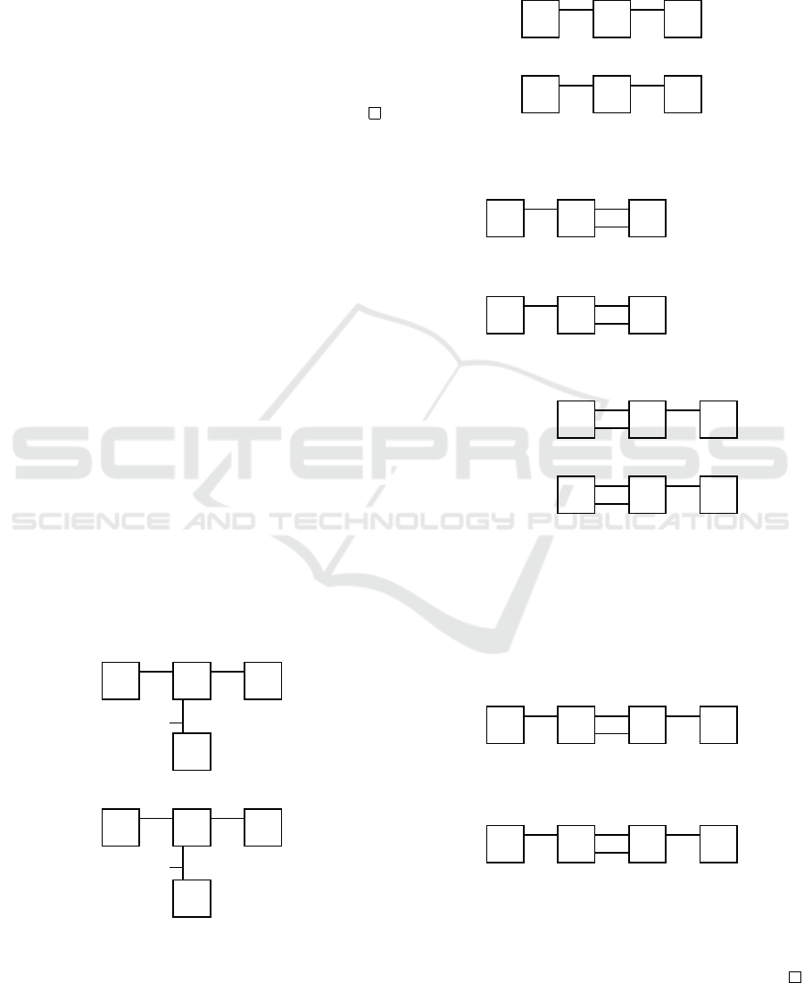
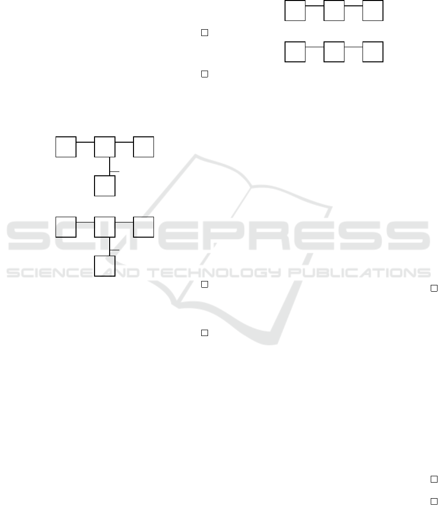
X
1
: r
1
: Q
A
1
(q
1
0
), R
A
2
,A
1
(b) −→ Q
A
(q
1
1
), R
A
2
,A
1
(∗)
r
2
: Q
A
1
(q
1
1
), R
A
1
,A
2
(∗) −→ Q
A
(q
1
0
),R
A
1
,A
2
(a)
r
3
: Q
A
1
(q
1
1
), R
A
2
,A
1
(c) −→ Q
A
1
(q
1
2
), R
A
2
,A
1
(∗)
r
4
: Q
A
1
(q
1
2
), R
A
1
,A
3
(∗),−→ Q
A
1
(q
1
0
), R
A
1
,A
3
(a)
r
5
: Q
A
1
(q
1
0
), R
A
3
,A
1
(b) −→ Q
A
(q
1
3
), R
A
3
,A
1
(∗)
r
6
: Q
A
1
(q
1
3
), R
A
1
,A
3
(∗) −→ Q
A
(q
1
0
), R
A
1
,A
3
(a)
X
2
: s
1
: Q
A
2
(q
2
0
), R
A
2
,A
2
(∗) −→ Q
A
2
(q
2
1
), R
A
2
,A
2
(b)
s
2
: Q
A
2
(q
2
1
), R
A
2
,A
1
(∗), R
A
2
,A
2
(b) −→
Q
A
2
(q
2
2
),R
A
2
,A
1
(b), R
A
2
,A
2
(∗)
s
3
: Q
A
2
(q
2
2
), R
A
1
,A
2
(a) −→ Q
A
(q
2
0
), R
A
1
,A
2
(∗)
X
3
: p
1
: Q
A
3
(q
3
0
),R
A
1
,A
3
(a), R
A
3
,A
1
(∗) −→
Q
A
3
(q
3
1
), R
A
1
,A
3
(∗), R
A
3
,A
1
(b)
p
2
: Q
A
3
(q
3
1
), R
A
1
,A
3
(∗),−→ Q
A
3
(q
3
0
),R
A
1
,A
3
(∗)
Figure 3: Instructions of the Example LAS.
Figure 3. Notice that the hypercycle contains no rules
of A
3
. Starting from the initial configuration S
0
, any
infinite trace of N is obtained as the concatenation of
this hyper-cycle. Hence, N is periodic.
Moreover, each automaton rule is applied at most
once in a hyper-cycle, hence N is an LAS. N is func-
tionally correct since the fact Q
A
1
(q
1
2
) is not reachable
from S
0
using only system rules.
However, in the presence of an intruder, critical
configuration is reachable. There is an attack on
system N by message insertion by an intruder, using
only the rule i
c
: R
A
2
,A
1
(∗) −→ R
A
2
,A
1
(c) once. A
trace from S
0
starting with rules s
1
,s
2
,r
1
, followed
by the intruder rule i
c
reaches the configuration to
which the rule r
3
can be applied:
Q
A
1
(q
1
0
), Q
A
2
(q
2
0
), Q
A
3
(q
3
0
), R
A
2
,A
2
(∗),
R
A
1
,A
2
(∗), R
A
2
,A
1
(∗), R
A
1
,A
3
(∗), R
A
3
,A
1
(∗) −→
s
1
Q
A
1
(q
1
0
), Q
A
2
(q
2
1
), Q
A
3
(q
3
0
), R
A
2
,A
2
(b),
R
A
1
,A
2
(∗), R
A
2
,A
1
(∗), R
A
1
,A
3
(∗), R
A
3
,A
1
(∗) −→
s
2
Q
A
1
(q
1
0
), Q
A
2
(q
2
2
), Q
A
3
(q
3
0
), R
A
2
,A
2
(∗),
R
A
1
,A
2
(∗), R
A
2
,A
1
(b), R
A
1
,A
3
(∗), R
A
3
,A
1
(∗) −→
r
1
Q
A
1
(q
1
1
), Q
A
2
(q
2
2
), Q
A
3
(q
3
0
), R
A
2
,A
2
(∗),
R
A
1
,A
2
(∗), R
A
2
,A
1
(∗), R
A
1
,A
3
(∗), R
A
3
,A
1
(∗) −→
i
c
Q
A
1
(q
1
1
), Q
A
2
(q
2
2
), Q
A
3
(q
3
0
), R
A
2
,A
2
(∗),
R
A
1
,A
2
(∗), R
A
2
,A
1
(c), R
A
1
,A
3
(∗), R
A
3
,A
1
(∗) −→
r
3
Q
A
1
(q
1
2
), Q
A
2
(q
2
2
), Q
A
3
(q
3
0
), R
A
2
,A
2
(∗),
R
A
1
,A
2
(∗), R
A
2
,A
1
(∗), R
A
1
,A
3
(∗), R
A
3
,A
1
(∗)
By inserting the signal c into the appropriate channel,
intruder causes A
1
not to procede within the hyper-
cycle, but instead to apply rule r
3
. The resulting con-
figuration is critical as it contains the fact Q
A
1
(q
1
2
).
Therefore, the above trace represents an attack. Fur-
thermore, the above finite attack trace can be extended
into an infinite trace with no hyper-cycles of N , in
which automata A
1
and A
3
play an infinite ping pong
game, while A
2
is stuck. There are no hyper-cycles
in the above attack trace. It suffices for an intruder to
apply just a single action of message insertion to per-
form the attack and change the behavior of the system.
This example shows that even a well designed,
functionally correct PAS, including the case of a LAS,
in the presence of an intruder is no longer periodic.
5.3 Security Complexity Results
We investigate the complexity of deciding whether a
functionally correct AS can reach a critical configura-
tion in the presence of an intruder.
Definition 5.4 (Security Problem for Functionally
Correct Systems (SP-FCS)). Given an AS N that is
functionally correct and an intruder model I , is there
a trace using the rules of N and I leading from the
initial configuration to a critical configuration of N ?
We investigate the complexity of the SP-FCS for
different classes of AS and intruders. Recall from
Section 5.2 that, given an AS that is a LAS or a PAS,
once the intruder is present it may no longer be either.
Theorem 5.5. The SP-FCS is PSPACE-complete.
The SP-FCS PSPACE-complete even in the case the
intruder in question can apply only one action.
These problems are still PSPACE-complete even in
the case of a PAS and a LAS, and even in the case
the intruder can apply only one action.
Proof Sketch. For the lower bound, in order to in-
corporate the intruder, we modify the proof of The-
orem 4.12 accordingly. Upper bound follows from
Theorem 4.11. For more details see Appendix.
The above results are summarized in Table 1.
6 AUTOMATED VERIFICATION
The formal models, verification problems, and com-
plexity results support the automated security verifi-
cation of I4.0 applications. We demonstrate this by
carrying out a number of experiments based on the
Maude formalization described in (Nigam and Tal-
cott, 2019). Our experiments are based on the follow-
ing variations of the example described in Section 3.
PnP - This is the scenario described in Section 3.
2PnP - This scenario is a LAS containing two in-
stances of PnP and a coordinator that ensures the
start of each instance of PnP starts at the same
time, namely, the start of the hyper-cycle.
PnP-2Msgs - This scenario modifies the logic of
the PnP so that the track at the right (where the
caps are) waits for two signals to head leftwards
(where the cap has to be placed): GoL from ctl and
HasVac/NoVac from vac; and when vac is on it re-
quires two signals to turn off: VacOff from ctl and
ICISSP 2021 - 7th International Conference on Information Systems Security and Privacy
50

Table 2: Model-checking results for the SP-FCS using Maude for different scenarios. The values in parentheses, ×n, for a
scenario and bound on the intruder, denotes that Maude traversed n times more configurations than the scenario PnP with the
same value for the bound on the intruder. The experiments were run on a MacBook Pro, 2.4 Ghz Intel Core i5, 16GB memory.
Scenario Bound on Intruder Number of Configurations Explored Time(ms) SP-FCS
PnP
0 23 4 no
1 84 11 yes
2 406 47 yes
3 1651 178 yes
2PnP
0 84 (×3.7) 40 no
1 388 (×4.6) 182 yes
2 2873 (×7.1) 1409 yes
3 26440 (×16.0) 19631 yes
PnP-2Msgs
0 29 (×1.3) 40 no
1 722 (×8.5) 177 no
2 1854 (×4.6) 912 yes
3 10248 (×6.2) 4965 yes
2PnP-2Msgs
0 114 (×4.9) 88 no
1 6814 (×81.1) 5277 no
2 22179 (×54.1) 18208 yes
3 153824 (×93.1) 225898 yes
atL from track. Intuitively, this means that the in-
truder would need at least two actions to lead this
system to a critical configuration.
2PnP-2Msgs - This scenario is similar to the sce-
nario 2PnP, but uses PnP-2Msgs instead of PnP.
For each scenario, we carried out experiments in
Maude to check the reachability of critical configura-
tions in the presence of a bounded intruder with the
bound on the number of intrusions between 0 and 3.
Note that unreachability with the bound 0 corresponds
to checking whether the system is functionally cor-
rect. For the scenarios, we use the critical configura-
tions as described in Section 3. Table 2 summarizes
experiments on the four scenarios described above.
These experiments show that it is feasible in prac-
tice to formally verify simple scenarios and even more
complicated ones. However, as expected from our
complexity results, the computational effort, i.e., the
number of configurations explored increases expo-
nentially as we increase the size of the system. More-
over, increasing the bound on intruders impacts the
search space. Higher bound values mean that intrud-
ers are capable to carry out more complex attacks,
e.g., in the scenarios 2PnP and 2PnP-2Msgs the in-
truder needs at least two actions to carry out an attack.
7 CONCLUSIONS AND FUTURE
WORK
This paper introduces a formal model based on MSR
for representation and verification of automated inter-
connected systems such as I4.0 applications. Within
the general framework, several classes of systems are
identified, each with specific properties that are inter-
esting, and motivated by concrete applications. Dif-
ferent verification problems are investigated and a
comprehensive collection of complexity results is ob-
tained, including several security complexity results
involving different types of intruders.
There is a number of ways the model of automata
systems introduced in this paper can be extended. For
example, systems with smart devices as components,
systems of distributed manufacturing, and similar sys-
tems could be considered, for which the communica-
tion among systems components would follow cryp-
tographic networking protocols. At the same time, an
intruder with encryption capabilities, more similar to
DY intruder could be modelled.
In order to avoid some false positives, the model
could be extended with time, using timed MSR mod-
els (Kanovich et al., 2017) obtaining timed system
and intruder models that take into account physical
properties such as distances and processing time.
Similar to the work in (AlTurki et al., 2018), sta-
tistical model-checking could be applied to investi-
gate the success rates of various intruder strategies.
Additionally, systems and intruders with various
resource-sensitive features may lead to investigations
of other verification problems, such as the ones con-
sidered in (Urquiza et al., 2019).
For each of these extensions, we plan to investi-
gate abstraction techniques and properties similar to
(Nigam and Talcott, 2020) that relate various exten-
sions of our model.
On Security Analysis of Periodic Systems: Expressiveness and Complexity
51

ACKNOWLEDGMENTS
Part of this work was done during the visits to the University
of Pennsylvania by Alturki, Ban Kirigin, Kanovich, Nigam,
and Talcott, which were partially supported by ONR grant
N00014-15-1-2047 and by the University of Pennsylva-
nia. Ban Kirigin is supported in part by the Croatian Sci-
ence Foundation under the project UIP-05-2017-9219. The
work of Max Kanovich was partially supported by EP-
SRC Programme Grant EP/R006865/1: “Interface Reason-
ing for Interacting Systems (IRIS).” Nigam is partially sup-
ported by NRL grant N0017317-1-G002, and CNPq grant
303909/2018-8. Scedrov is partially supported by ONR
grants N00014-20-1-2635 and N00014-18-1-2618. Tal-
cott was partially supported by ONR grants N00014-15-1-
2202 and N00014-20-1-2644, and NRL grant N0017317-1-
G002.
REFERENCES
Ademaj et al. (2019). Time sensitive networks for flexible
manufacturing testbed - description of converged traf-
fic types, IIC white paper.
AlTurki, M. A., Kanovich, M., Ban Kirigin, T., Nigam,
V., Scedrov, A., and Talcott, C. (2018). Statisti-
cal model checking of distance fraud attacks on the
Hancke-Kuhn family of protocols. In Proceedings of
the 2018 Workshop on Cyber-Physical Systems Secu-
rity and PrivaCy, pages 60–71. ACM.
Biere, A., Cimatti, A., Clarke, E. M., Strichman, O., and
Zhu, Y. (2003). Bounded model checking. Advances
in Computers, 58:117–148.
Cyberattack Has Caused Confirmed Physical Dam-
age for the Second Time Ever. (2015).
Available at https://www.wired.com/2015/01/
german-steel-mill-hack-destruction/.
Clavel, M., Durán, F., Eker, S., Lincoln, P., Martí-Oliet,
N., Meseguer, J., and Talcott, C. (2007). All About
Maude: A High-Performance Logical Framework,
volume 4350 of LNCS. Springer.
Dolev, D. and Yao, A. (1983). On the security of public key
protocols. IEEE Transactions on Information Theory,
29(2):198–208.
Durgin, N. A., Lincoln, P., Mitchell, J. C., and Scedrov,
A. (2004). Multiset rewriting and the complexity of
bounded security protocols. Journal of Computer Se-
curity, 12(2):247–311.
ENISA (2018). Good practices for security of internet of
things in the context of smart manufacturing.
Fiat, M. and et.al. (2017). OPC UA security analysis.
Kanovich, M., Ban Kirigin, T., Nigam, V., and Scedrov, A.
(2013). Bounded memory protocols and progressing
collaborative systems. In ESORICS, pages 309–326.
Kanovich, M. I., Ban Kirigin, T., Nigam, V., and Scedrov,
A. (2014). Bounded memory Dolev-Yao adversaries
in collaborative systems. Inf. Comput., 238:233–261.
Kanovich, M. I., Ban Kirigin, T., Nigam, V., Scedrov, A.,
and Talcott, C. L. (2017). Time, computational com-
plexity, and probability in the analysis of distance-
bounding protocols. Journal of Computer Security,
25(6):585–630.
Kanovich, M. I., Rowe, P., and Scedrov, A. (2011). Col-
laborative planning with confidentiality. Journal of
Automated Reasoning, 46(3-4):389–421.
Lanotte, R., Merro, M., Munteanu, A., and Viganò, L.
(2020). A formal approach to physics-based attacks
in cyber-physical systems. ACM Trans. Priv. Secur.,
23(1).
Nigam, V. and Talcott, C. (2019). Formal security verifi-
cation of industry 4.0 applications. In ETFA, Special
Track on Cybersecurity in Industrial Control Systems.
Nigam, V. and Talcott, C. (2020). Automated construction
of security integrity wrappers for industry 4.0 applica-
tions. In International Workshop on Rewriting Logic
and its Applications (WRLA).
Savage, J.E.(1998). Models of computation. Addison-
Wesley Reading, MA
Urquiza, A. A., AlTurki, M. A., Kanovich, M., Ban Kirigin,
T., Nigam, V., Scedrov, A., and Talcott, C. (2019).
Resource-bounded intruders in denial of service at-
tacks. In 32nd Computer Security Foundations Sym-
posium (CSF), pages 382–396. IEEE.
Yoong, L. H., Roop, P. S., Bhatti, Z. E., and Kupz, M. M. Y.
(2015). Model-Driven Design Using IEC 61499:
A Synchronous Approach for Embedded Automation
Systems. Springer.
Zoitl, A. and Lewis, R. (2014). Modelling control systems
using IEC 61499. Control Engineering Series 95. The
Institution of Electrical Engineers, London.
APPENDIX
PSPACE-hardness in Theorem 4.12
Theorem 4.12. FCP for PAS is PSPACE-hard.
Remark 7.1. For the sake of readability, here, and
henceforth, we will abbreviate Eq.(1) as:
q,R
B
1
,A
(m
1
),..,R
B
k
,A
(m
k
) → q
0
,R
A,C
1
(m
0
1
),..,R
A,C
`
(m
0
`
)
(5)
The PSPACE decision problem can be defined as:
“Given a Turing machine M running in space m,
determine whether there is a binary string x of
length m so that x is accepted by M.”
We reformulate the problem in terms of
e
M, which
deals only with one and the same initial configuration
fixed in advance.
Lemma 7.2. Given a deterministic Turing machine M
running, say, in space m = n/3, we construct a deter-
ministic Turing machine
e
M running in space n so that
for its fixed initial tape of the form
n times
z}|{
aa..a and its initial
ICISSP 2021 - 7th International Conference on Information Systems Security and Privacy
52
state q
1
,
e
M always terminates but in one of the two
states:
e
q
0
or
e
q
1
.
Moreover,
e
M terminates in
e
q
0
iff one can find a
binary string x of length m so that x is accepted by M.
Besides,
e
M is constructed so that
e
M starts with
its initial state q
1
at the leftmost position on the tape
and terminates with
e
q
0
or with
e
q
1
at the same leftmost
position on the tape. There are no moves in
e
M from
e
q
0
or
e
q
1
. Each
e
M’s command, qξ → q
0
ηD, must “move”
to the left, which is marked by D = −1, or to the right,
which is marked by D = +1.
Our goal is to mimic the terminated computation
performed by
e
M in terms of hyper-cycles from A
0
to A
0
, where the automaton A
0
, the ‘main controller’
in our system, is specified by the following instruc-
tions (r
0
is its initial state)
r
0
−→ r
0
0
, R
A
0
,A
1
(p)
R
B
n+1
,A
0
(
e
q), r
0
0
, −→ r
0
, where
e
q ∈ {
e
q
0
,
e
q
1
}
(6)
Initially all channels are empty. A
0
starts its hyper-
cycle with sending signal p to A
1
via channel R
A
0
,A
1
.
Then A
0
is waiting for a signal
e
q sent from B
n+1
to
end its hyper-cycle.
We develop our AS by designing the automata we
need step by step using a chain of lemmas. To ease
technicalities, we define the automata at hand only in
terms of the tasks the automata should perform.
As signals, we use q, ξ, η, and q
0
, etc., the tape
symbols and states of
e
M. We use p as a specific extra
signal. In addition, we introduce a polynomial num-
ber of fresh signals, hq
0
,η, Di, to represent triples of
the form (q
0
,η, D).
Providing
e
M’s Initial Tape
Lemma 7.3. For 1 ≤ i ≤ n, we design A
i
so that A
i
can transform a precondition of the form
A
i
-
*
A
i−1
A
i+1
-
p
?
*
B
i
into a postcondition of the form
A
i
-
p
A
i−1
A
i+1
-
*
?
a
B
i
Then we provide the initial tape for
e
M, aa..a, by se-
quential execution of automata A
1
, A
2
, . . . , A
n
, re-
sulting in the ‘initial’ non-empty channels R
A
1
,B
1
(a),
R
A
2
,B
2
(a), . . . , R
A
n
,B
n
(a).
Simulating
e
M’s Computations
Lemma 7.4. To provide the correct start of
e
M with
its initial state q
1
, we design A
n+1
so that A
n+1
trans-
forms the precondition produced by the n-th step of
Lemma 7.3
A
n+1
-
*
A
n
B
1
-
p
into a postcondition of the form
A
n+1
-
q
1
A
n
B
1
-
*
Lemma 7.5. Given a Turing command qξ → q
0
ηD,
first we design B
i
, i = 1, ..,n, so that B
i
can transform
a precondition of the form, j 6= i,
A
j
B
i
A
i
B
i
-
q
-
*
ξ
into the following postcondition, where
m = hq
0
,η, Di:
A
j
B
i
A
i
B
i
-
*
-
m
*
and we modify A
i
so that, in addition to Lemma 7.3,
A
i
can transform a precondition of the form (recall
D = ±1)
B
i+D
B
i
A
i
A
i
-
*
-
m
*
into the following postcondition,
B
i+D
B
i
A
i
A
i
-
q
0
-
*
η
Lemma 7.6. Any computation performed by
e
M can
be one-to-one simulated by running sequentially the
corresponding ordered pairs of automata B
i
and A
i
.
Proof. Suppose that, being in state q and scanning ξ
in i-th tape cell,
e
M applies its command qξ → q
0
ηD.
By induction we represent the enabling conditions
for the above
e
M’s move as a reachable configuration
of the form
A
j
B
i+D
B
i
A
i
-
*
-
q
-
*
ξ
By Lemma 7.5 the following configuration that repre-
sents the enabling conditions for the next
e
M’s move,
is reachable:
A
j
B
i+D
B
i
A
i
-
q
0
-
*
-
*
η
Lemma 7.7. Our system behaves deterministically.
Proof. By induction we show that the enabling con-
ditions are not overlapped at any moment, so that no
more than one automaton instruction can be applied
at the current moment.
On Security Analysis of Periodic Systems: Expressiveness and Complexity
53
Lemma 7.8. For
e
q ∈ {
e
q
0
,
e
q
1
},
e
M terminates in
e
q iff
R
A
2
,B
1
(
e
q) is reachable within our system.
In particular, R
A
2
,B
1
(
e
q
0
) is reachable iff one can find a
binary string x of length m so that x is accepted by M.
Proof. The direction “only if” is the most problem-
atic. Suppose that R
A
2
,B
1
(
e
q) is reachable, but
e
M ter-
minates in some
e
q
0
. Then by Lemma 7.6 R
A
2
,B
1
(
e
q
0
)
must be reachable as well, and Lemma 7.7 requires
e
q
0
=
e
q.
Corollary 7.9. Claiming R
A
2
,B
1
(
e
q
0
) critical provides
PSPACE-hardness for functional correctness.
Proof. Follows from Lemmas 7.2 and 7.8.
Collecting Garbage
Lemma 7.10. For 1 ≤ i ≤ n, we modify B
i
so that, in
addition to Lemma 7.5, B
i
can transform the precon-
dition
B
i
-
*
B
i−1
B
i+1
-
e
q
6
ξ
A
i
into the ‘cleaner’ postcondition
B
i
-
e
q
B
i−1
B
i+1
-
*
6
*
A
i
For i = 1, we take A
2
as B
i−1
.
At the end of the hyper-cycle, we nullify all chan-
nels R
A
i
,B
i
with Lemma 7.10 applied sequentially.
Our system given in this Section is a periodic sys-
tem with a unique hyper-cycle from A
0
to A
0
.
PSPACE-hardness in Theorem 5.5
Theorem 5.5: The SP-FCS is PSPACE-complete.
The SP-FCS PSPACE-complete even in the case the
intruder in question can apply only one action.
These problems are still PSPACE-complete even in
the case of a PAS and a LAS, and even in the case
the intruder can apply only one action.
We investigate a restricted decision problem:
“Given as input to the problem: a locally bounded
periodic AS, which is functionally corect, and an in-
truder, which can apply only one action, determine
whether a critical configuration is reachable within
the system enriched with the intruder action.”
As input to the problem we take an AS from Defi-
nition 7.11 and an intruder from Definition 7.14.
Definition 7.11. For a fixed
e
M from Lemma 7.2, we
take the system introduced in this Section and replace
only one lemma, Lemma 7.4, with Lemma 7.12.
Lemma 7.12. We update A
n+1
so that A
n+1
can trans-
form the precondition produced by the n-th step of
Lemma 7.3
A
n+1
-
*
A
n
B
1
-
p
into a postcondition of the form
A
n+1
-
e
q
1
A
n
B
1
-
*
As critical we take system configurations which
contain R
A
2
,B
1
(
e
q
0
) at some moment of execution.
Lemma 7.13. The system given in Definition 7.11 is
a LAS which is functionally correct.
Proof. According to Lemmas 7.3, 7.12, and 7.10, we
can develop a unique hyper-cycle from A
0
to A
0
by
running sequentially the following automata
A
0
,A
1
,A
2
,. ..,A
n
,A
n+1
,B
1
,B
2
,. ..,B
n
,B
n+1
,A
0
.
Initially all channels are empty. A
0
starts a hyper-
cycle with sending signal p to A
1
via channel R
A
0
,A
1
.
Sequentially running A
1
,. ..,A
n
results in the non-
empty channels R
A
1
,B
1
(a), . . . , R
A
n
,B
n
(a). At once
Lemma 7.12 redirects the execution to the garbage
collecting Lemma 7.10, which makes channels empty.
Consuming R
B
n+1
,A
0
(
e
q
1
) at state r
0
0
, A
0
ends the cur-
rent hyper-cycle.
Notice that the automaton instructions involved in
the above execution in question have been applied no
more than once.
Definition 7.14. Let an intruder be able to attack the
updated A
n+1
, by changing its outgoing signal
e
q
1
into
the signal q
1
by means of the following action that
modifies the channel R
A
n+1
,B
1
:
R
A
n+1
,B
1
(
e
q
1
) −→ R
A
n+1
,B
1
(q
1
) (7)
Lemma 7.15. For
e
q ∈ {
e
q
0
,
e
q
1
},
e
M terminates in
e
q iff
R
A
2
,B
1
(
e
q) is reachable within our system in Defini-
tion 7.11 enriched with the intruder action (7).
Proof. Similar to Lemma 7.8.
At the moment when A
n+1
provides R
A
n+1
,B
1
(
e
q
1
)
by Lemma 7.12, the intruder redirects the execution
to ‘sleeping’ automata by modifying a channel of the
form R
A
n+1
,B
1
(
e
q
1
) into R
A
n+1
,B
1
(q
1
).
The result is that at the next moment B
1
starts not
with
e
q
1
but with q
1
, the true initial state of
e
M.
Bringing all things together we complete the proof
of Theorem 5.5.
ICISSP 2021 - 7th International Conference on Information Systems Security and Privacy
54
