
AR-Bot, a Centralized AR-based System for Relocalization and Home
Robot Navigation
Matthieu Fradet, Caroline Baillard, Vincent Alleaume, Pierrick Jouet, Anthony Laurent and Tao Luo
InterDigital, Rennes, France
Keywords:
Augmented Reality, Robot Navigation, Relocalization, 3D Registration, 3D Modeling.
Abstract:
We describe a system enabling to assign navigation tasks to a self-moving robot in a domestic environment,
using an Augmented Reality application running on a consumer-grade mobile phone. The system is composed
of a robot, one or several mobile phones, a robot controller and a central server. The server embeds automatic
processing modules for 3D scene modeling and for device relocalization. The user points at a target location
in the phone camera view and the robot automatically moves to the designated point. The user is assisted
with AR-based visual feedback all along the experience. The novelty of the system lies in the automatic
relocalization of both the robot and the phone: they are independently located in the 3D space thanks to
registration methods running on the server, hence they do not need to be explicitly spatially registered to each
other nor in direct line of sight. In the paper we provide details on the general architecture and the different
modules that are needed to get a fully functional prototype. The proposed solution was designed to be easily
extended and may be seen as a general architecture supporting intuitive AR interfaces for in home devices
interactions.
1 INTRODUCTION
Augmented Reality (AR) technology is evolving very
rapidly. It has become very present in the industry,
and AR-based consumer applications are more and
more popular (gaming, interior design, virtual try-on,
etc.). AR consists in adding virtual content in a live
view of the real-world environment and enables to de-
sign intuitive user interfaces for interacting with sur-
rounding objects.
We are living in an era where a large number of
devices communicate with each other or access ser-
vices hosted in the cloud. A recent related trend is the
development of the Internet of Things (IoT), which il-
lustrates the need to establish an end-to-end commu-
nication structure, from low-level but power efficient
wireless exchanges to higher level protocols managed
by one or more servers. As a side effect, it is common
to get system architectures with many protocol lay-
ers, each one having a specific role in the final appli-
cations and services. Using AR technology and such
protocols, it is possible to visually select and control
connected objects in a natural manner, like turning on
a light for instance, using either a phone or a head-
set (Heun, 2017; Zaki et al., 2019; Becker et al., 2019;
Jo and Kim, 2019).
In this paper, we focus on the use of AR for con-
trolling a moving robot. In robotics, AR can act as
a user-friendly interface for exchanging information
between the user and autonomous systems, increasing
the efficiency of Human-Robot Interactions (HRI). As
robots become more and more prevalent in our pro-
fessional and private life, it becomes vital to find an
easy and intuitive way to control them. We propose a
fully automatic multisensory solution called AR-Bot,
which enables to easily move an autonomous robot
(typically a vacuum cleaner) towards a target point,
thanks to the use of an AR-based mobile interface
and automatic 2D/3D registration methods. Instead
of typically using a 2D floor map representation to
indicate to the robot where it should go to, the user
simply points at the target location in the camera view
of the phone. The user is assisted with AR-based vi-
sual feedback which enables a better precision in the
location selection. After validation the system sum-
mons the robot to move to the selected location. An
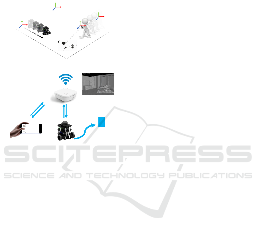
overview of the solution is depicted in Figure 1. The
system leverages several communication protocols to
manage heterogeneous data whilst keeping high effi-
ciency. Unlike other similar solutions, the initial posi-
tion of the robot relatively to the phone does not need
to be explicitly determined. Instead, a reference 3D
Fradet, M., Baillard, C., Alleaume, V., Jouet, P., Laurent, A. and Luo, T.
AR-Bot, a Centralized AR-based System for Relocalization and Home Robot Navigation.
DOI: 10.5220/0010190506370645
In Proceedings of the 16th International Joint Conference on Computer Vision, Imaging and Computer Graphics Theory and Applications (VISIGRAPP 2021) - Volume 4: VISAPP, pages
637-645
ISBN: 978-989-758-488-6
Copyright
c
2021 by SCITEPRESS – Science and Technology Publications, Lda. All rights reserved
637
model of the scene is stored on a server and used
for the respective relocalization of the robot and the
phone with respect to the environment.
MS
RS
CS
WS
(a) from a usage perspective
Phone
relocaliza�on
x
Target
posi�on
Move to
target
Target
selec�on
(b) from a communication perspective
Figure 1: Overview of the AR-Bot solution.
The paper is organized as follows. Section 2
presents some related work. In Section 3 we pro-
vide a high-level description of the AR-Bot ecosys-
tem with details on devices, architecture and robot
operating mode. In Section 4 we describe the user
interactions and the global workflow. Section 5 pro-
vides some details about the processing modules that
are involved, e.g. the coordinate system management,
the scene modeling, the robot and phone relocaliza-
tion modules. Some elements of discussion are pro-
vided in Section 6, before conclusion in Section 7.
2 RELATED WORK
Many AR-based robotic systems have been proposed
in recent years, with applications in various do-
mains such as medical robotics, robot programming,
motion planning, collaborative interfaces, or robot
swarms (Makhataeva and Varol, 2020; Piumatti et al.,
2017; Kuriya et al., 2015; Kundu et al., 2017; Guhl
et al., 2017).
An early system called TouchMe allows the user
to manipulate each part of a robot by directly touching
it on a view of the world, as seen by a camera look-
ing at the robot from a third-person view (Hashimoto
et al., 2011). Each robot is equipped with a marker
and user interactions are done through a PC.
In (Kasahara et al., 2013), the authors present Ex-
Touch, a system to control devices through an AR-
based mobile interface. When users touch a mov-
ing device shown in live video on the screen, they
can change its position and orientation through multi-
touch gestures or by physically moving the screen in
relation to the controlled object. However the target
position of the moving device can only be given with
respect to the current position.
In (Frank et al., 2017), the authors propose a mo-
bile mixed-reality interface approach to enhance HRI
in shared spaces. A common frame of reference is
created for the user and the robot to effectively com-
municate spatial information and perform object ma-
nipulation tasks. The robots are also affixed with vi-
sual markers to locate them in the environment.
A more elaborate solution called PinpointFly en-
ables users to arbitrarily position and rotate a fly-
ing drone using an AR-based interface running on
a smartphone, where the position and direction of
the drone are visually enhanced with a virtual cast
shadow (Chen et al., 2019). In this system as well,
the target position is defined with respect to the orig-
inal position. It also requires a calibration step with
a chessboard and there is no management of the sur-
rounding environment.
Recently, in (Manring et al., 2020), a Microsoft
HoloLens headset has been used to create an AR en-
vironment to control a robot: the user places a virtual
robot in 3D space, then uses the virtual robot to con-
trol the motion of the real robot. The real robot is
manually positioned in the real environment.
This type of systems offers easy ways to interact
with robots, but the initial position of the robot rela-
tively to the phone needs to be explicitely determined,
which requires manual initializations or visual mark-
ers to be set on the robot.
3 SYSTEM OVERVIEW
3.1 Devices
The system includes a robot, one or several phones,
and a central server (see Figure 1b). It also comprises
a wireless network part connecting the robot and the
mobile phone(s) to the server, as well as other wired
connection elements such as a desktop PC server do-
ing the heavy processing.
The robot is equipped with a LiDAR which is used
for the spatial registration with the real-world envi-
VISAPP 2021 - 16th International Conference on Computer Vision Theory and Applications
638
ronment. The robot navigation is achieved through
the Robot Operating System (ROS) (ROS, 2013).
The phone is used for both modeling the scene in
3D and for controlling the robot. These two tasks can
be achieved by different users with different phones.
For 3D scene reconstruction we only need an RGB
camera. In particular, we do not need any embed-
ded or external depth sensor. For the robot control-
ling interface the phone needs to support ARKit or
ARCore (ARKit, 2020; ARCore, 2019).
3.2 Server Architecture
In the AR-Bot ecosystem, the server consists of two
elements. The first one, “Robot Controller”, over-
sees the robot control. It relies on ROS, a frame-
work mostly focused on managing robot(s) in a pos-
sibly widely distributed setup. The second element,
“AR-Bot server”, embeds processing modules and a
network interface, a HTTP server, for communicat-
ing with the smartphones. To facilitate a distributed
architecture, the communication between both server
elements is based on the Message Queuing Teleme-
try Transport (MQTT) protocol, a publish-subscribe-
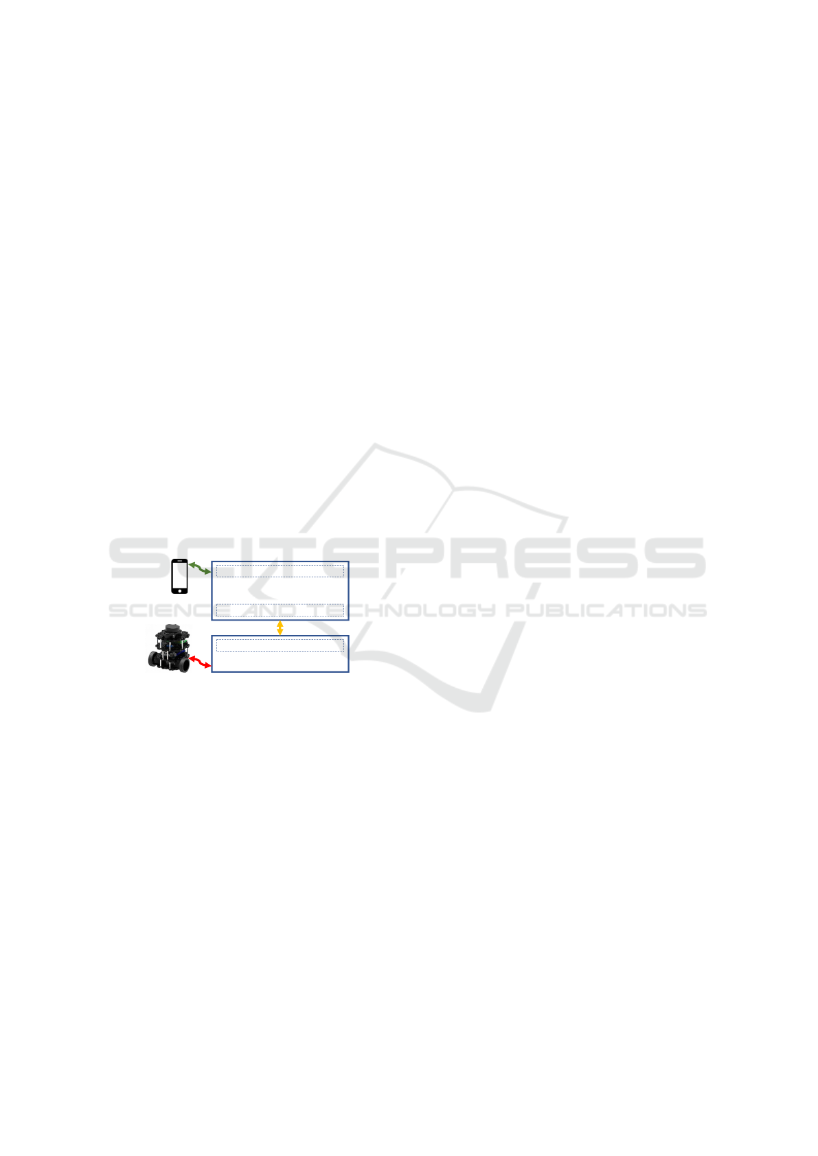
based messaging protocol (MQTT, 2016). The dia-
gram in Figure 2 depicts the high-level architecture.
AR-Bot server
MQTT client
Robot Controller (ROS)
HTTP server
MQTT client
Figure 2: High-level overview of the architecture.
3.3 ROS
The ROS framework provides libraries and tools to
help software developers create robot applications. It
combines many roles that can be hosted on one single
machine (a robot for instance), or inversely be spread
onto multiple machines communicating through a
network (ROS, 2013). The main node, the ROS Mas-
ter, provides naming and registration services to the
other nodes. Also based on a publisher/subscriber
approach, some nodes provide services, some others
generate data at various frequencies on so-called top-
ics, and some others subscribe to such topics to pro-
cess data when broadcasted, or make use of services
from other nodes.
When a ROS node is started on a machine, this
one must be properly setup regarding the ROS envi-
ronment, and specifically regarding the ROS Master
node defined by its network name or IP address. Some
nodes may also require that machines participating to
the same ROS setup share a very precise time base;
this is typically the case when the robot publishes
timestamped LiDAR data, but relies on another node
to generate its neighborhood map for moving around.
This last requirement was solved by defining a unique
local Network Time Protocol (NTP) server in the sys-
tem (NTP, 1992) that is used for the time synchro-
nization of all the devices, including the robot.
4 EXPERIENCE DESCRIPTION
4.1 User Interface
The main user interactions are related to the mobile
relocalization (to align the world reference with other
used coordinate systems) and the robot target assign-
ment.
When starting a new session, the phone is first
connected to the server. Then it is localized in the
physical world before the user can select a target lo-
cation for the robot. For this purpose, an image is cap-
tured by the user and sent to the server for relocaliza-
tion computation. The method is explained in Subsec-
tion 5.5. When the relocalization is completed, a vir-
tual planar polygon corresponding to the ground area
is displayed in semi-transparency on the top of the
camera view. This visual feedback enables the user
to qualitatively check the relocalization consistency.
The computation of the ground area is explained in
Subsection 5.3.
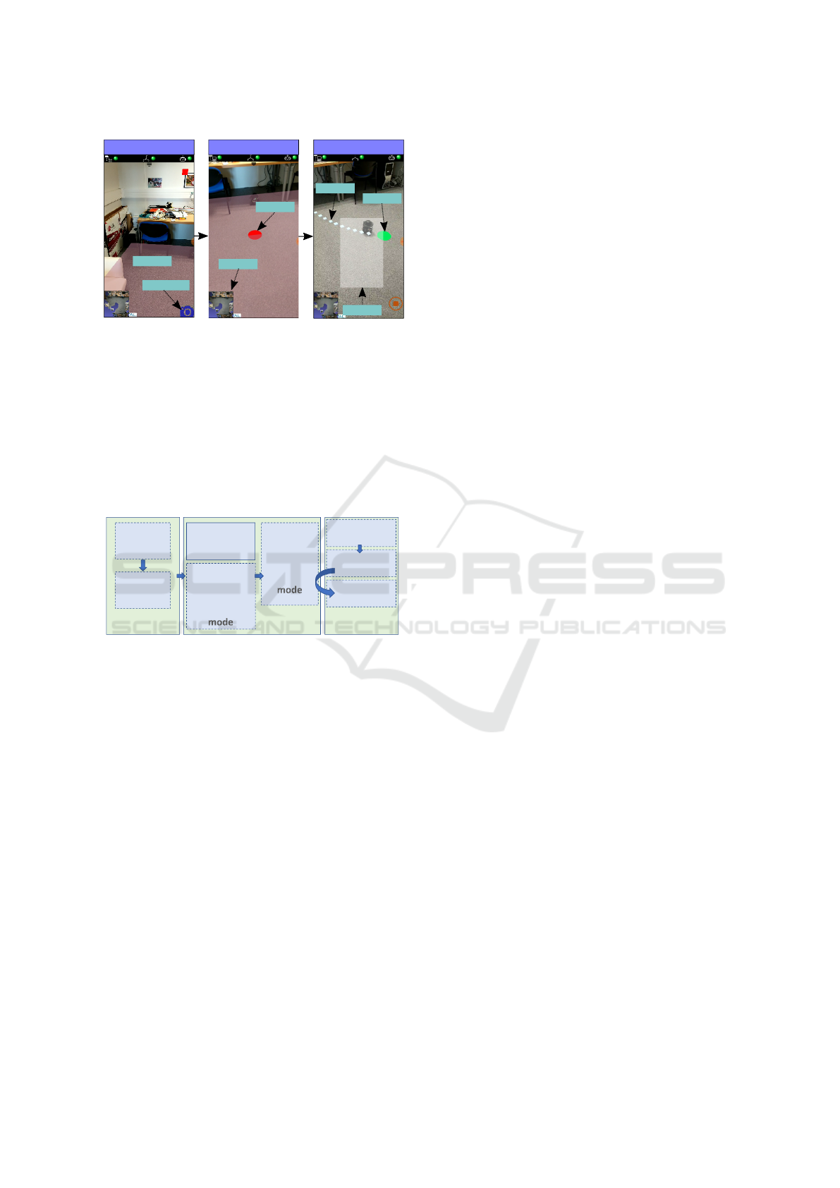
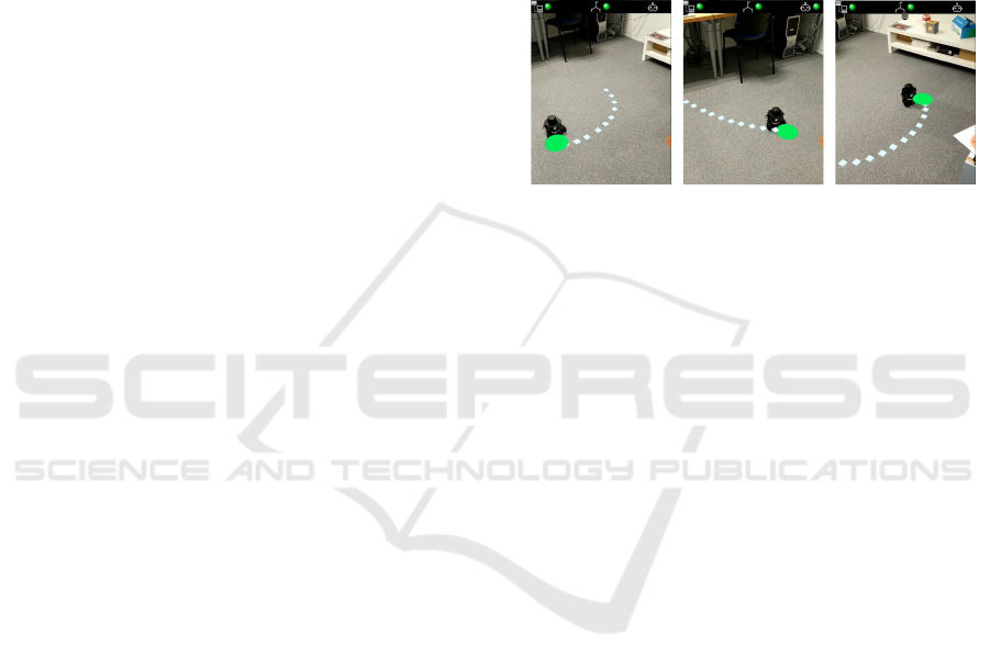
In order to summon the robot, the user simply taps
on a desired location on the visualized ground plane
(see the selection pointer as a red dot in Figure 3).
This casts a virtual ray that is thrown with respect to
the underlying scene model aligned with the location.
If a collision with the ground area is detected, the hit
point is set as the new robot target and it is rendered
in AR on the user screen via a green dot.
Finally, the “move” command is sent to the server
as a new HTTP request. The path followed by the
robot is displayed in AR on the user screen, following
the robot motion in real-time. The mobile application
also informs the user about the command result via a
textual pop up.
A top view of the scene is also rendered as a
thumbnail in the corner of the screen, to help the user
having an overview of the environment (see Figure 3).
AR-Bot, a Centralized AR-based System for Relocalization and Home Robot Navigation
639
Target Definition
Moving
Capture btn
Path
Floor
The robot has
reached the
target
successfully.
Pointer
Target
Message
Relocalization
Top view
Figure 3: Graphical User Interface of the mobile applica-
tion during three states. From left to right: relocalization
initiated using a capture button and visualized using a vir-
tual floor plane; target selection using a pointer (red circle);
robot displacement with visualization of path (white dots),
target (green circle) and end message.
4.2 Workflow
The overall workflow is presented in Figure 4 and
consists of a set of pre-processing processes followed
by a set of runtime processes.
Move-To
ac�vity
Naviga�on
Robot
Watching
ac�vity
3D scene
modeling
Scene map
genera�on
Relocaliza�on
ac�vity
Explora�on
Run�me
(ROS related)
Run�me
(Mobile related)
Phone
Relocaliza�on
Target
Selec�on
Message
Display
Pre-processing
Figure 4: Overall workflow of the sytem including several
steps, modes and activities, with runtime being detailed be-
tween ROS related tasks and mobile oriented tasks.
4.2.1 Pre-processing Processes
The scene in which the robot operates is first mod-
eled. The modeling process is twofold, including 3D
scene modeling and scene map generation, both re-
quired at runtime. The 3D scene modeling module is
described in Subsection 5.2. The scene map is a 2D
representation of the 3D scene model and it is used
in the runtime period to support robot relocalization
and navigation. The scene map computing module is
described in Subsection 5.3. This module also deter-
mines the ”ground area”. This pre-processing step is
only required once but must be performed again each
time the scene layout changes.
4.2.2 Runtime Processes
The part of the workflow dedicated to the robot in-
cludes specific elements referred as modes and ac-
tivities, which are presented in Figure 4. We have
split the robot behavior into two modes named “ex-
ploration” and “navigation”, each of them including
one or several activities corresponding to a given task
to accomplish.
At runtime period, the first activity to be launched
is the Robot Watching activity, in charge of detecting
and periodically checking the presence of the robot in
the system (connected, ready). This is also the last
activity to be stopped.
Assuming a robot is detected, the first mode to be
activated is exploration, which involves launching all
the standard ROS nodes enabling the robot building a
robot map of its surroundings. Starting with the Re-
localization activity, the robot moves a few seconds
straight forward then stops to build the robot map.
This latter is registered with the scene map generated
during pre-processing to estimate the robot pose in the
reference model (see Subsection 5.4). If the relocal-
ization request does not succeed, more time is given
to the robot to further explore and capture the envi-
ronment, then a new relocalization request is sent.
If the robot relocalization succeeds, then the ex-
ploration mode is stopped along with related ROS
nodes, and the navigation mode is launched. It starts
all the ROS nodes needed for navigation (path esti-
mation, ...) with the particularity of using the scene
map rather than the partial robot map. Obstacle de-
tection and related path computation are however dy-
namically updated using live information update, as
commonly used in ROS environment.
As for the mobile phone, it is first relocalized in
the scene (see Subsection 5.5). When the user selects
a target and requests the robot to move to this desig-
nated target, then the Move-To activity of the robot
is engaged, using the target point as a standard ROS
goal destination. The task is done by polling the vari-
ous messages related to the navigation operation: the
dynamic robot position is updated several times per
second, and the final success or failure of the robot
route is also polled, then forwarded to the system and
the user in the relevant coordinate system. Textual ex-
planations are provided to the user in all cases, using
a pop up to display the message on the screen.
5 PROCESSING MODULES
The processing modules are hosted on the system
server for performance considerations.
5.1 Coordinate System Management
The AR-Bot system maintains knowledge about the
environment of the user and the robot as a recon-
VISAPP 2021 - 16th International Conference on Computer Vision Theory and Applications
640
structed 3D model, while also getting updated infor-
mation about their respective position and orientation
within this environment. However, the mobile appli-
cation and the robot use different coordinate systems.
The server is in charge of transforming the position
data between different coordinate systems. More pre-
cisely, the 3D position of the designated target needs
to be represented within the 2D map representation
which is used by the robot for navigation; recipro-
cally, the periodically updated robot position, pro-
vided with respect to its 2D map, needs to be con-
verted back into a 3D representation compatible with
the AR-based user interface.
We distinguish the following coordinate systems
(schematically represented in Figure 1a):
• Model Space (MS): the coordinate system of the
reconstructed scene model,
• Robot Space (RS): the robot map coordinate sys-
tem used for the robot navigation,
• World Space (WS): the coordinate system of the
mobile device AR session. To track the mo-
bile device in the physical space we rely on the
world tracking concept of the AR Foundation
framework available within Unity (ARFounda-
tion, 2020), so that at every instant we get the pose
of the mobile device with respect to the so-called
“World Space” (WS), which varies for each ses-
sion since it directly depends on the real world
position that the session starts with.
• Camera Space (CS): the coordinate system at-
tached to the camera of the mobile device.
5.2 3D Modeling
Various solutions can be used for the reconstruction
of a 3D scene model, depending on available sensors
(depth sensors, color cameras). We decided to de-
velop our overall AR-Bot system without any use of
depth sensors, so that most smartphones can be used.
Importantly, the captured data must enable the subse-
quent relocalization of the phone and the robot.
For the 3D modeling of the scene, a set of im-
ages is captured and sent to a tuned photogrammetry
pipeline based on OpenMVG (Moulon et al., 2016).
This includes an important rescaling step which is in-
teractively performed by the user, once per scene re-
construction. This step ensures that the reconstructed
scene scale corresponds to the real world one. The
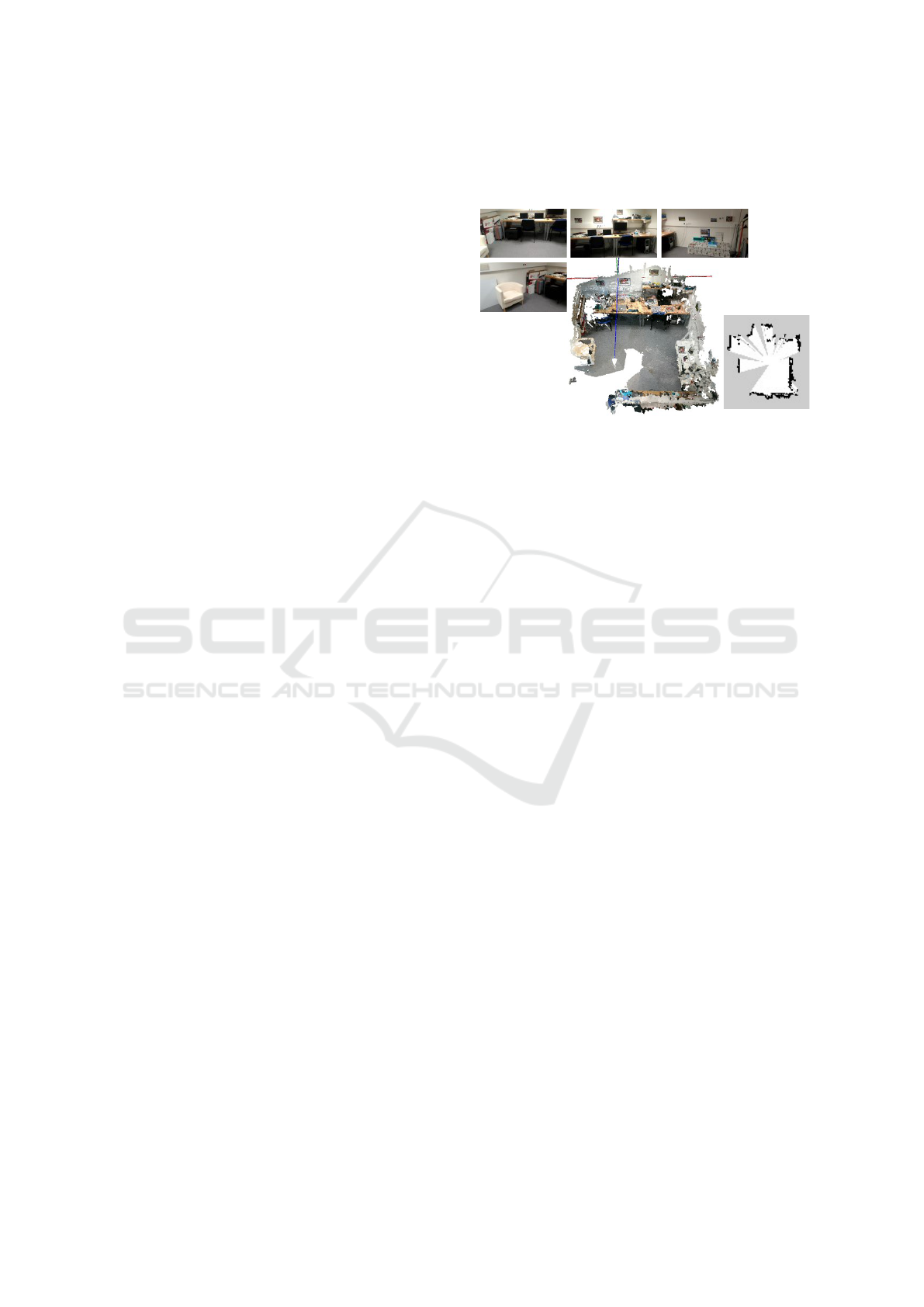
number of images depends on the complexity of the
environment (in dimension, texture, etc.). For in-
stance, the room in Figure 5 has required about 50
images to be modeled.
A 3D point cloud is generated as an output further
used to estimate the scene map and the ground area as
explained in Subsection 5.3. Along with this 3D point
cloud, the image poses and the key-points extracted
during the reconstruction are also stored.
Figure 5: 3D modeling stage: from image sequence (only 4
are shown) to dense scene point cloud (centre), allowing the
generation of a scene map at the robot height (right), which
is compatible with ROS use; occupied pixels are black, free
pixels are white, and unknown pixels are grey.
5.3 Scene Map and Ground Area
The control of the robot requires a 2D scene map,
which is computed during the pre-processing step, as
presented in Figure 4. Within this step we also deter-
mine the ground area, which is needed in the user in-
terface to provide feedback on the relocalization and
to select the target (see Subsection 4.1). The genera-
tion of both the scene map and ground area is based
on the analysis of the reconstructed 3D point cloud.
Given the height of the robot LiDAR, a slice 3D
point cloud is cropped in parallel to the ground plane
at the robot height to generate a 2D scene map. To
ensure having enough data, we also crop the partial
data above and below the slice plane with a prede-
fined margin. Then, by using the same meta-data as
the robot map (e.g. map resolution, pose of map ori-
gin, pixel values to indicate occupancy probability),
the cropped point cloud is projected onto the image
plane, whose pixels are valuated to indicate whether
they are occupied, free or unknown. An example of
2D scene map is shown in Figure 5. Note that at this
stage, the scene map must be reformatted to match the
ROS underlying map representation, hence enabling
the use of ROS navigation.
In addition, planes are extracted from the 3D point
cloud based on geometric criteria, then classified into
horizontal and vertical planes, assuming that the grav-
ity direction is the inverse direction of the Y-axis in
the Model Space. The ground plane is determined
as the furthest significant horizontal plane along the
gravity direction. The wall planes are selected among
the vertical planes that surround the scene point cloud.
AR-Bot, a Centralized AR-based System for Relocalization and Home Robot Navigation
641
Finally, ground corners are extracted as the intersec-
tion points between the wall planes and the ground
plane, which defines the ground area.
5.4 Robot Relocalization
The relocalization and navigation of a robot using
ROS is a standard use case which is commonly solved
with dedicated nodes. These nodes process data com-
ing from the robot LiDAR and from wheel sensors
(odometry). They enable the computation of a 2D
robot map around the robot, and the estimation of its
location. However, both relocalization and naviga-
tion are accomplished in the Robot Space, the coor-
dinate system attached to the robot. In order to con-
trol the motion of a robot with the AR-Bot applica-
tion, it is necessary to locate this robot in the Model
Space, with respect to the scene model. The problem
of robot relocalization is hence regarded as comput-
ing the transformation between the current robot map
and the 3D scene model. Therefore, while the tar-
get destination is first specified in the Model Space, it
must be converted into the robot map to enable the au-
tonomous navigation of the robot. Besides, the scene
map generated in Subsection 5.3 can also be trans-
formed to replace the current robot map if necessary.
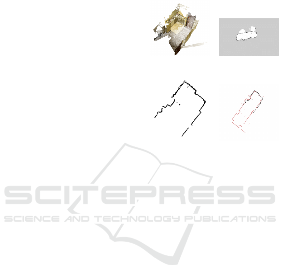
In our work, the computation of the transforma-
tion between the 2D robot map and the 3D model is
accomplished by registering their corresponding slice
point clouds. In Figure 6a, the 3D point cloud of a do-
mestic scene is reconstructed using the pipeline pro-
posed in Subsection 5.2, and the 2D robot map cap-
tured by the robot is shown in Figure 6b. These het-
erogeneous data should be converted into a consistent
representation for the registration. For the scene point
cloud in Figure 6a, a slice point cloud (Figure 6c) is
cropped in parallel to the detected ground plane with
the known height of the robot LiDAR. For the 2D
robot map, the occupied pixels (black in Figure 6b)
are converted to a slice point cloud (red in Figure 6d)
using the map meta-data (resolution, origin, etc.). The
conversion into slice point clouds constrains the relo-
calization/registration problem to 2D and reduces the
number of parameters to be optimized.
In the registration process, a coarse-to-fine strat-
egy is employed at different levels of data represen-
tation. For the two slice point clouds, the struc-
tural representations are first extracted, e.g. lines
and key points. Then an initial alignment is imple-
mented based on these structural representations to
get a coarse result using the algorithm of 4-points con-
gruent sets (Aiger et al., 2008). To refine the registra-
tion, an ICP-based method is applied to the two slice
point clouds, initialized with the coarse alignment.
(a) 3D scene model (b) 2D robot map from the
robot
(c) slice 3D point cloud
from scene model
(d) registration between
slice point clouds
Figure 6: Robot relocalization in scene model. In (d), the
slice point cloud of the scene model is in black, while the
slice point cloud of the 2D robot map is in red.
The relocalization is considered as being success-
ful when two conditions are met: 1) the ratio between
the area sizes of the partial robot map and the scene
map is above a given threshold value (set to 0.3),
which guarantees that the partial robot map contains
enough information for the registration; 2) the regis-
tration error, defined as the maximum point-to-point
distance between the corresponding points of both
slice point clouds, is below a given threshold value
(set to 15 cm). In this case, we consider that the robot
is successfully relocalized in the Model Space. An
example of registration result is shown in Figure 6d.
The transformation between the 3D scene model and
the 2D robot map is retrieved using the transformation
between these two slice point clouds. Thus, the nav-
igation to the target destination can be accomplished
by ROS nodes with obstacle avoidance using the cap-
tured robot map or the transformed scene map.
5.5 Phone Relocalization
On the mobile device side, we have developed a user-
friendly AR application powered by Unity. For the
relocalization of the mobile device in the environ-
ment, we rely on our client-server architecture: the
client mobile device captures a single camera frame
and sends it to the server for processing.
When the server receives a relocalization request,
it launches the relocalization computation based on
VISAPP 2021 - 16th International Conference on Computer Vision Theory and Applications
642
OpenMVG to relocalize the image into the scene re-
constructed during pre-processing. The output of this
relocalization computation is the camera pose in the
Model Space, at the time the request image was cap-
tured. As said earlier, we rely on AR Foundation to
track the mobile device in the World Space all along
the AR session. To bridge the gap between the World
Space and the Model Space, we transit through the
Camera Space at the time the image to be relocalized
was captured, and thus simply multiply transform ma-
trices to finally reach the Model Space. The camera
pose in the World Space is provided by AR Foun-
dation and stored when capturing the request image.
The camera pose in the Model Space is computed on
the server by the relocalization module.
6 EXPERIMENTATION AND
DISCUSSION
For our experiments, we used a TurtleBot3 BURGER
robot (TurtleBot3, 2020), for which the original low-
range LiDAR was upgraded to a LiDAR RPLIDAR
A2M8 (2D scan on 360
◦
, range up to 12 meters).
This robot is a 3-wheel low-size robot, fully con-
trolled through a multi-interface and a controller card
chained to a common Raspberry Pi 3 card. It runs a
Raspbian Linux distribution as well as ROS packages
needed for ROS environment to manage this specific
robot model and equipment.
We used two different smartphones to validate the
fact that the offline 3D reconstruction and the run-
time phone relocalization can be performed with dif-
ferent phone models. The color pictures used as input
of the 3D reconstruction pipeline were captured with
the rear high-resolution camera of an Asus ZenFone
AR (with no use of the depth sensing camera), while
the end-user mobile device was the Google Pixel 2
XL, an Android smartphone supporting ARCore.
The robot controller and the AR-Bot server were
both hosted on the same Linux PC.
We experimented the system in different rooms of
the lab, with different geometric characteristics and
different acquisition conditions. Figure 7 shows some
examples captured in our main demo room.
In our informal testing involving targeting task,
and in comparison to the traditional pointing on a
static 2D floor map, we found that our AR ap-
proach significantly improves mobile robot naviga-
tion in terms of accuracy, efficiency and user expe-
rience satisfaction. If our AR system imposes the
users to have the target in sight when selecting it, it
is not perceived as a limitation since they get the sat-
isfaction of visually perceiving live the virtual target
overlapping the desired location. Also, because our
centralized solution does not require any manual in-
tervention to designate the initial location of the robot
w.r.t. the phone, the users can start controlling it with-
out even having to think about its current location.
The navigation task is considered successful when
the robot reaches the target designated with the phone.
The quality of the experience therefore mainly de-
pends on two factors: the quality of the robot relo-
calization on one hand, and the quality of the phone
relocalization on the other hand.
Figure 7: Examples of robot final position when reaching
the target.
6.1 Robot Relocalization
The robot relocalization is mainly impacted by the
limitations in the LiDAR sensor accuracy, which gen-
erally appear in case of very poor or ambiguous geo-
metric details. For instance, if the robot is close to a
long planar wall with no geometric features, or if the
robot is located in a large room with no furniture or
wall within the LiDAR range, then the relocalization
cannot be achieved. In this case it is necessary that the
robot acquires more data before performing the relo-
calization process. In our implementation, after being
started, the robot autonomously moves for 30 seconds
for scanning its environment before sending the relo-
calization request. In case of failure, a new request
is sent 30 seconds later to enable the robot to further
capture the environment. The impact on the experi-
ence is that the user might have to wait longer for the
robot to start the task.
In some cases, although the initial relocalization
of the robot is correct, we found out that the inter-
nal robot tracking system could sometimes fail. This
typically happens when the odometry information is
taken into account whereas it should not (for instance,
wheels slipping on the floor when the robot is stuck
under furniture such as a chair). Using additional in-
formation coming from LiDAR sensor could help a
lot to detect and handle such cases.
AR-Bot, a Centralized AR-based System for Relocalization and Home Robot Navigation
643
6.2 Phone Relocalization
The computation time required for phone relocaliza-
tion (including data transfers) is about 2 seconds. We
implemented it as an asynchronous task so that the ap-
plication does not freeze during this time. Since the
relocalization approach is based on the output of the
3D reconstruction pipeline, no specific marker is re-
quired in the scene. Assuming a reasonably textured
scene, the phone relocalization can be computed from
any frame and any point of view, as long as the areas
visible from this point of view have already been ob-
served and reconstructed when modeling the environ-
ment.
The precision of the phone relocalization depends
on many factors including the precision of the 3D re-
construction, the accuracy of the intrinsic parameters
of the cameras, the image quality and the size of the
overlapping regions in the request and target images.
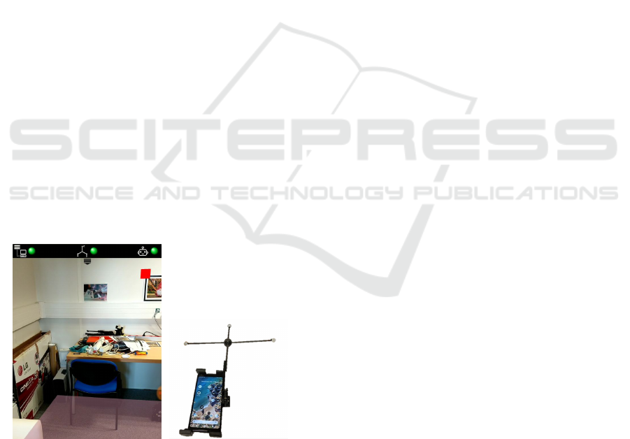
As a first experiment to qualitatively evaluate
the phone relocalization accuracy, we have displayed
small virtual objects at pre-determined locations that
correspond to locations of real physical objects (typ-
ically, a small virtual red cube on top of the ori-
gin of the reconstructed environment, or X, Y and Z
RGB axes to illustrate the basis of the environment).
Such a virtual red cube is visible in Figure 8 where
a real poster was voluntarily stuck on the wall for
this specific evaluation use (also used for the inter-
active rescaling step performed during pre-processing
as mentioned in Subsection 5.2). Please note that this
poster is NOT used for marker-based relocalization or
marker-based tracking.
Figure 8: Phone relocalization evaluation. Left: Virtual red
cube displayed on the top of the image to visually validate
the relocalization accuracy. Right: Smartphone prototype
with OptiTrack marker used during our experiments unfor-
tunately suspended due to lockdown.
From what we observed in the first tests:
• the relocalization accuracy varies between 5 and
20 cm,
• the relocalization is successful in 9 cases out of
10,
• blurry request images should be carefully
avoided, meaning that the user must pay particu-
lar attention to stabilize the device when sending
the relocalization requests,
• some new relocalization computations may be re-
quired during a session to compensate for tracking
drifts or failures (e.g. after few seconds in dark-
ness if light has been switched off/switched on).
In this type of application dedicated to robot navi-
gation within a room (for cleaning tasks for instance),
an error of twenty centimeters on the target location
remains acceptable.
The evaluation of both the robot and the phone re-
localization quality clearly deserves a significant eval-
uation study, preferably based on some ground-truth
references. We started an encouraging quantitative
evaluation involving an OptiTrack kit (Figure 8) but it
was unfortunately suspended as we could not access
our facilities anymore due to COVID-19 containment.
7 CONCLUSION
We have presented a full solution to control an au-
tonomous robot equipped with a LiDAR, using a sim-
ple and intuitive AR-based interface running on a mo-
bile device. It relies on an ecosystem comprising
the robot, the mobile device, a robot controller and
a central server. The added value of the system is
to have both phone and robot independently located
within the same 3D space. As a result, contrarily to
other comparable systems, they do not need to be ex-
plicitely spatially registered to each other nor in di-
rect line of sight, and it is possible for instance to
summon a robot which is not visible by the phone.
Furthermore, their respective positions within the 3D
scene can be accessed and displayed at any time. The
key point of the solution is the use of dedicated reg-
istration algorithms and their integration into a global
system. Experimentations have showed that the relo-
calization of both the robot and the phone is accurate
enough to achieve the desired task. The proposed so-
lution was designed to be easily extended and may be
seen as a general architecture supporting intuitive AR
interfaces for in home devices interactions. The next
step is to assess the system with a quantitative accu-
racy evaluation and a proper user study.
A valuable improvement would be the automatic
management of the image-based phone relocalization,
without having the user to explicitly send a request
image. Another point that would also deserve future
investigations is the automatic detection of erroneous
VISAPP 2021 - 16th International Conference on Computer Vision Theory and Applications
644

positioning of the robot, in order to automatically
launch the relocalization process whenever required.
This would be useful when the user takes the robot to
place it somewhere else without notifying the system
(“kidnapping” problem), or when the robot gets tem-
porarily stuck in a place (under a piece of furniture, on
a carpet...). As a longer-term work, a full home net-
work environment could be considered, with multiple
robots (possibly of different types: vacuum cleaner,
washer, domestic robot) and multiple users, each user
having different roles and rights.
REFERENCES
Aiger, D., Mitra, N., and Cohen-Or, D. (2008). 4-points
congruent sets for robust pairwise surface registration.
35th International Conference on Computer Graphics
and Interactive Techniques (SIGGRAPH’08), 27.
ARCore (2019). ARCore. https://developers.google.com/
ar/discover. Last checked on 2020-09-14.
ARFoundation (2020). ARFoundation. https:
//docs.unity3d.com/Packages/com.unity.xr.
arfoundation@4.0/manual/index.html. Last checked
on 2020-09-14.
ARKit (2020). ARKit. https://developer.apple.com/
augmented-reality/arkit/. Last checked on 2020-09-
14.
Becker, V., Rauchenstein, F., and S
¨
or
¨
os, G. (2019). Inves-
tigating Universal Appliance Control through Wear-
able Augmented Reality. In Proceedings of the 10th
Augmented Human International Conference 2019,
AH2019, New York, NY, USA. Association for Com-
puting Machinery.
Chen, L., Ebi, A., Takashima, K., Fujita, K., and Kita-
mura, Y. (2019). Pinpointfly: An egocentric position-
pointing drone interface using mobile ar. In SIG-
GRAPH Asia 2019 Emerging Technologies, SA ’19,
page 34–35, New York, NY, USA. Association for
Computing Machinery.
Frank, J., Moorhead, M., and Kapila, V. (2017). Mo-
bile Mixed-Reality Interfaces That Enhance Hu-
man–Robot Interaction in Shared Spaces. Frontiers
in Robotics and AI, 4.
Guhl, J., Tung, S., and Kruger, J. (2017). Concept and
architecture for programming industrial robots using
augmented reality with mobile devices like microsoft
HoloLens. In 2017 22nd IEEE International Confer-
ence on Emerging Technologies and Factory Automa-
tion (ETFA), pages 1–4.
Hashimoto, S., Ishida, A., and Inami, M. (2011). TouchMe:
An Augmented Reality Based Remote Robot Ma-
nipulation. In The 21st International Conference
on Artificial Reality and Telexistence, Proceedings of
ICAT2011.
Heun, V. M. J. (2017). The reality editor: an open and
universal tool for understanding and controlling the
physical world. PhD thesis, Massachusetts Institute
of Technology.
Jo and Kim (2019). AR Enabled IoT for a Smart and Inter-
active Environment: A Survey and Future Directions.
Sensors, 19(19):4330.
Kasahara, S., Niiyama, R., Heun, V., and Ishii, H. (2013).
Extouch: Spatially-aware embodied manipulation of
actuated objects mediated by augmented reality. In
Proceedings of the 7th International Conference on
Tangible, Embedded and Embodied Interaction, TEI
’13, page 223–228, New York, NY, USA. Association
for Computing Machinery.
Kundu, A., Mazumder, O., Dhar, A., Lenka, P., and Bhau-
mik, S. (2017). Scanning Camera and Augmented
Reality Based Localization of Omnidirectional Robot
for Indoor Application. Procedia Computer Science,
105:27–33.
Kuriya, R., Tsujimura, T., and Izumi, K. (2015). Aug-
mented reality robot navigation using infrared marker.
In 2015 24th IEEE International Symposium on Robot
and Human Interactive Communication (RO-MAN),
pages 450–455.
Makhataeva, Z. and Varol, A. (2020). Augmented reality
for robotics: A review. Robotics, 9:21.
Manring, L., Pederson, J., Potts, D., Boardman, B., Mas-
carenas, D., Harden, T., and Cattaneo, A. (2020).
Augmented Reality for Interactive Robot Control. In
Dervilis, N., editor, Special Topics in Structural Dy-
namics & Experimental Techniques, Conference Pro-
ceedings of the Society for Experimental Mechanics
Series, volume 5, pages 11–18. Springer, Cham.
Moulon, P., Monasse, P., Perrot, R., and Marlet, R. (2016).
Openmvg: Open multiple view geometry. In Interna-
tional Workshop on Reproducible Research in Pattern
Recognition, pages 60–74. Springer.
MQTT (2016). ISO/IEC 20922:2016 - Information
technology - Message Queuing Telemetry Transport
(MQTT) v3.1.1. https://www.iso.org/standard/69466.
html. Last checked on 2020-09-14.
NTP (1992). Network Time Protocol (Version 3) specifica-
tion. https://tools.ietf.org/html/rfc1305. Last checked
on 2020-09-14.
Piumatti, G., Sanna, A., Gaspardone, M., and Lamberti,
F. (2017). Spatial Augmented Reality meets robots:
Human-machine interaction in cloud-based projected
gaming environments. In IEEE International Con-
ference on Consumer Electronics (ICCE), pages 176–
179.
ROS (2013). About ROS. https://www.ros.org/about-ros/.
Last checked on 2020-09-14.
TurtleBot3 (2020). TurtleBot3. http://emanual.robotis.com/
docs/en/platform/turtlebot3/overview/. Last checked
on 2020-09-14.
Zaki, M., Hakro, D., Memon, M., Zaki, U., and Hameed,
M. (2019). Internet Of Things Interface Using Aug-
mented Reality: An Interaction Paradigm using Aug-
mented Reality. University of Sindh Journal of Infor-
mation and Communication Technology, 3:135 – 140.
AR-Bot, a Centralized AR-based System for Relocalization and Home Robot Navigation
645
