
Proposal of a Troposphere Model in Simulation for Automotive
Applications
Angelo Arieta
1
, Mauro Tropea
1
and Danilo Amendola
2
1
Dimes Department, University of Calabria, via P. Bucci 39/c, 87036 Rende (CS), Italy
2
University of Trieste, Piazzale Europa, 1, 34127, Trieste, FVG, Italy
Keywords:
Automotive, Troposphere Model, GNSS Simulator, GPS Receiver.
Abstract:
The Global Navigation Satellite System (GNSS) is the standard generic term for satellite navigation systems
that provide global coverage and it includes GPS, GLONASS, Galileo and other regional satellite navigational
systems. The use of simulator for performing different kinds of test is a practice largely used that provides
many advantages in different navigation systems thanks to the possibility of performing tests under controlled
and repeatable conditions in a secure laboratory. The use of GPS simulation is largely used for testing GPS
receivers. This paper presents a GNSS simulator for automotive applications, in particular the software used is
GPS-SDR-SIM, an open source simulator written in C language and it proposes a simulator improvement pro-
viding the implementation of the Troposphere Collins model in order to improve the accuracy of the simulation
experiments.
1 INTRODUCTION
The Global Navigation Satellite System (GNSS) is
the standard generic term for satellite navigation sys-
tems that provide global coverage. This term includes
GPS, GLONASS, Galileo, Beidou and other regional
satellite navigational systems (Van Sickle and Dutton,
2014; Groves, 2015).
It is a geo-radiolocation for a terrestrial, marine or
air navigation system, which uses a network of artifi-
cial satellites in orbit. Thanks to this global coverage,
the receivers that are located anywhere on the Earth’s
surface or on the atmosphere, can determine their ge-
ographic coordinates by processing the RF signals
transmitted by satellites.
The GNSS network is composed of several con-
stellations. A satellite constellation is a group of satel-
lites used in a coordinated way that they can offer
global or partial coverage. Thanks to the trilateration
operation, the receiver located on the earth’s surface
is able to obtain its position, as each satellite con-
tinuously sends information regarding the ephemeris
(Tsui, 2005).
Ephemeris are information concerning the posi-
tion of the satellites, the clock (timing) and health
(Zhang and Ji, 2015). This information is sent
through the navigation message that is transmitted by
satellites and in the case of the Global Positioning
System (GPS) constellation, it is transmitted in two
frequencies which are 1575.42MHz and 1227.6MHz.
Figure 1: GNSS in a VANET scenario.
Today the GPS is considered an integrated part
of the system that composes the Vehicular Ad-Hoc
Network (VANET) (Ghori et al., 2018). The vehi-
cles are equipped with GPS receivers and, in the next
future, all vehicles will have a GNSS receiver on
board (Hasan et al., 2018). The research in the joint
use of GNSS and VANET shows a certain conver-
gence toward a common objective: how to improve
the GNSS systems exploiting VANETs by GNSS re-
searchers and the use of GPS information to improve
Quality of Service (QoS) and scalability by VANET
ones. In Figure 1, a typical use case of global po-
120
Arieta, A., Tropea, M. and Amendola, D.
Proposal of a Troposphere Model in Simulation for Automotive Applications.
DOI: 10.5220/0009970901200127
In Proceedings of the 10th International Conference on Simulation and Modeling Methodologies, Technologies and Applications (SIMULTECH 2020), pages 120-127
ISBN: 978-989-758-444-2
Copyright
c
2020 by SCITEPRESS – Science and Technology Publications, Lda. All rights reserved

sition system in a VANET environment is shown.
The vehicular network aims to improve road safety,
traffic and energy efficiency giving also attention to
the emission issues (Santamaria et al., 2019), (Fazio
et al., 2017). Different works focuses their attention
on mechanisms for advising dangerous or emergency
situations by exploiting on-board sensors (Santamaria
et al., 2018) also using predictive mechanism as in
(De Rango et al., 2008), (Fazio et al., 2016), (Frnda
et al., 2013). Moreover, very studied aspects for the
ad-hoc network are routing issue as it is possible to
view in (Zhou et al., 2006), (Fotino et al., 2007), (So-
cievole et al., 2011), and also for VANET is an impor-
tant topic as it is possible to view in (De Rango et al.,
2009), (Fazio et al., 2013).
Moreover, in the literature a lot of works exist that
base their approach on the use of geo-localization data
for routing purpose in order to improve the scalabil-
ity of routing within vehicular networks (Devangavi
and Gupta, 2017). Incoming automatic driving ap-
plications are going to require even tighter level of
precision and security in order to guarantee the high
required standard. The aviation sector, the first one to
develop GNSS integrity solutions, analysed in a very
detailed way many important aspects concerning the
use of GNSS accuracy information.
In this paper, the proposal of a Troposphere model
for GNSS simulator in automotive field has been pre-
sented. The simulator is GPS-SDR-SIM, an open
source simulator written in C language. The proposed
module implements the Troposphere Collins model in
order to improve the accuracy of the simulation exper-
iments.
The rest of this paper is organized as follows: Sec-
tion 2 presents the related work on the considered re-
search topic. In Section 3, a description of the GNSS
applications in VANET scenario is given. In Section
4, we describe the used simulator considered for de-
veloping additional software module.The numerical
results are presented in Section 5. Finally, Section
6 concludes the paper.
2 RELATED WORK
The scientific research of last decade has been char-
acterized by a rapid evolution of GNSS software re-
ceivers. Since the first GPS Standard Positioning Ser-
vice, different new systems are arisen able to pro-
vide global coverage and, they include GLONASS,
Galileo and other regional satellite navigational sys-
tems. And, in order to perform different tests about
navigation system in a secure and repeatable way, dif-
ferent software and hardware simulators are proposed
in the scientific community. In the literature, several
works were devoted to architectural and implementa-
tion aspects of GNSS simulators.
In (Deng and Wang, 2011) the authors propose
a simulation design of digital IF signal based on the
mathematical model of digital IF GPS signals. Their
have designed a simulator and their experimental re-
sults show that the structure of simulated signals is
closer to real signals.
The TUTGNSS Reference Receiver is a fully op-
erational GPS I Galileo receiver, developed at Tam-
pere University of Technology for educational pur-
poses (Paakki et al., 2010). It provides a platform for
testing and developing new algorithms for GNSS field
without ”black boxes”, allowing developers to have
full control over its further development.
The GNSS-SDR, an open source Global Naviga-
tion Satellite System software-defined receiver is pro-
posed in (Fernandez-Prades et al., 2001). The paper
describes the software architecture design and pro-
vides details about its implementation, targeting a
multiband, multisystem GNSS receiver. The authors
have built a testbed for GNSS signal processing able
to allow any kind of customization, including inter-
changeability of signal sources, signal processing al-
gorithms, interoperability with other systems, output
formats, and the offering of interfaces to all the inter-
mediate signals, parameters and variables.
An open source implementation of a GNSS soft-
ware receiver that targets Galileo E1B and E1C sig-
nals is discussed in (Fern
´
andez-Prades et al., 2012),
where the authors provide detailed descriptions of the
main signal processing algorithms involved in acqui-
sition and tracking of such navigation signals.
An open source GPS receiver software and labora-
tory hardware that is a straightforward modification of
a COTS receiver to interface it to a PC bus are shown
in (Kelley et al., 2002). In the paper, the authors de-
scribe the hardware and software architecture, the fea-
tures added to allow debugging of the code and carrier
tracking loops.
3 GNSS APPLICATION IN A
VANET SCENARIO
The number of applications that use the Global Nav-
igation Satellite System (GNSS) technology is con-
stantly increasing. Many of these have increasingly
stringent requirements so that in some cases it is nec-
essary to integrate GNSS technology with other tech-
nologies in order to meet the requirements of a partic-
ular application.
Proposal of a Troposphere Model in Simulation for Automotive Applications
121

To ensure that GNSS technology is forefront and
reliable, the design of the various parts of the system,
in particular GNSS receivers, must respect high stan-
dards and ensure reliable performance. To enable this,
it is important that the product development process
is based on appropriate tests from the concept to the
production.
Traditionally, GNSS testing has been subdivided
into following three distinct methods:
• Live sky testing
• Record and Replay methods
• Simulators
Nowadays, the best practices for testing GNSS re-
ceivers concern tests performed in a controlled and
repeatable manner in a safe laboratory (Paakki and
Nurmi, 2014).
This kind of approach allows to test all conditions,
including tests performed to the limits of real and
theoretical performance. This also allows the devel-
opment of receivers for GNSS systems currently un-
available or able to operate also with a non-complete
constellation.
The aim is to emulate the environment of a GNSS
receiver on a dynamic platform by modeling the
movement of the vehicle, the satellite, the character-
istics of the signal, the atmospheric effects and other,
making sure that the receiver actually navigates ac-
cording to the parameters of the test scenario. Un-
like road tests, simulator tests provide full control of
simulated satellite signals and simulated environmen-
tal conditions. In this way, testers can easily gener-
ate and run many different test scenarios for different
types of tests, with complete control over all simula-
tion parameters such as date, time position, vehicle
movement and environmental conditions.
The performance of a receiver varies on the basis
of errors and effects applied to the RF signal. Figure
2 shows a representation of the signal flow through a
GNSS simulator where additional effects are added,
up to the output that represents the input signal of the
trial receiver. The analysis of the simulation results
can be done in real time or by post-test analysis of
the recorded data. The access to simulation data (the
data used to create the test signal) can be obtained in
various ways: using streaming data or recording it in
a file. This data can then be used to compare receiver
performance with ”true” simulation data.
3.1 GPS-SDR-SIM: An Open Source
Simulator to Test GPS Receivers
GPS-SDR-SIM (Hu, 2019) is an open source software
written in C language that allows to generate base-
Figure 2: Representation of the signal flow through a GNSS
simulator.
band GPS data streams, which can be converted into
RF signals using Software Defined Radio (SDR) plat-
forms such as for example ADALM-Pluto (ada, 2019)
and HackRF One (hac, 2019).
To generate a GPS signal, the GPS constellation to
be used must be specified to the software. This can be
done thanks to a file called GPS broadcast ephemeris
file, which in the case of this study was downloaded
from the site (eph, 2019) where it is possible to down-
load the daily file containing information about the
constellation at a given moment (in RINEX format
(Gurtner and Estey, 2013)).
These files are then used to generate the simu-
lated pseudorange and doppler frequency for the GPS
satellites in sight. These simulated data are then used
to generate digitized I/Q samples for the GPS signal
(Rao and Falco, 2012).
The instant of simulation starting can be specified
if the corresponding set of ephemerides is available,
otherwise the first instant of ephemerides present in
the RINEX file is selected. In addition to the RINEX
file containing the satellite broadcast ephemeris, an
National Marine Electronics Association (NMEA)
file (a text file describing the coordinates of the re-
ceiver in the form of strings) for the vehicle coordi-
nates to simulate has to be provided. These coordi-
nates must have a frequency of 10Hz, which means
that 10 NMEA strings correspond to one second of
simulation. An NMEA GGA string specifies the po-
sition of the receiver; some of the most relevant pa-
rameters are: latitude, longitude, GPS signal quality,
and so on.
4 PROPOSED SOLUTION
To improve and add novel functionality to the simu-
lator, a model that takes into account the delay of the
signal when it crosses the space portion of the tropo-
sphere has been implement. In order to realize this
purpose, a valid model was selected to calculate the
effects of the signal based on the parameters avail-
able in the simulator. In Figure 3, a scheme that sum-
marizes the simulator functionality is shown. This
scheme highlights the additional block implemented
SIMULTECH 2020 - 10th International Conference on Simulation and Modeling Methodologies, Technologies and Applications
122
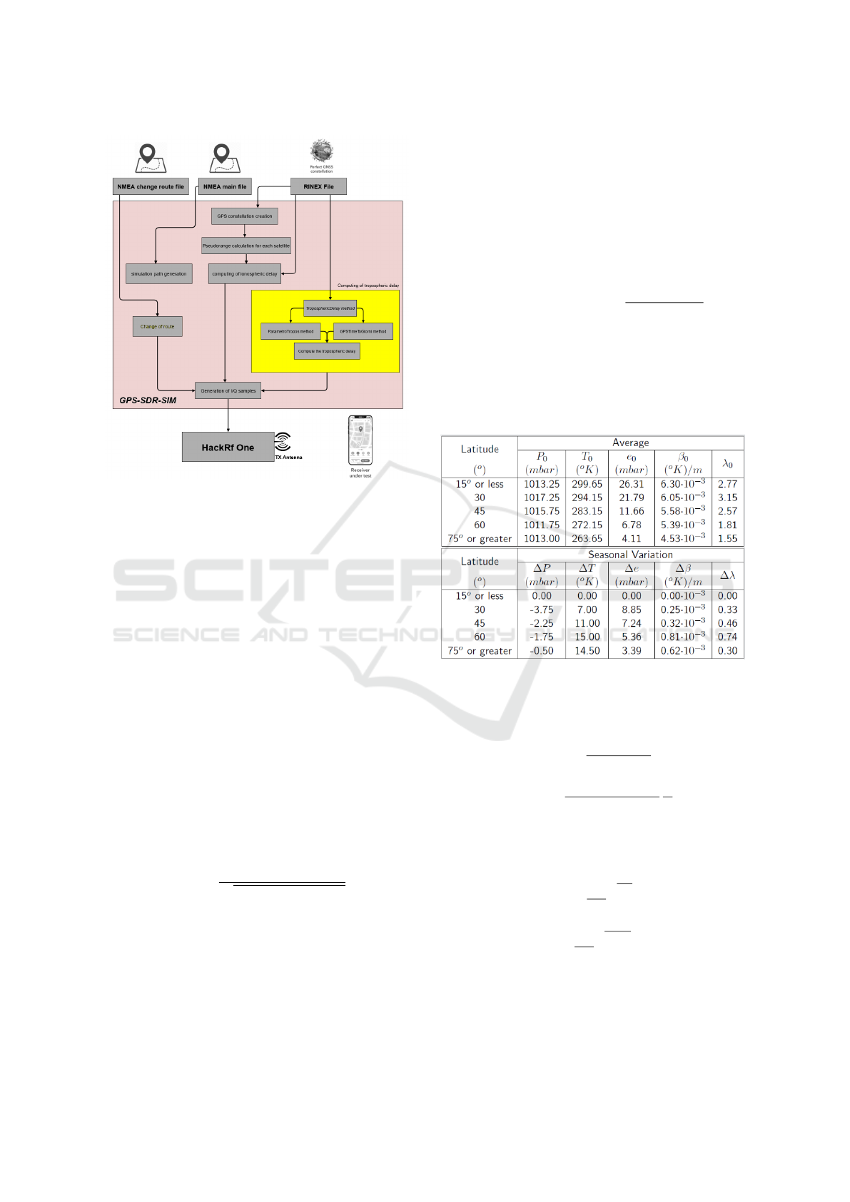
Figure 3: Simulator Block Diagram.
in the software.
In this work the Troposphere Collins model
(Collins, 1999) has been used. This model is also used
by Satellite-Based Augmentation System (SBAS)
systems for maximum precision differential correc-
tions, with the aim of increasing the accuracy and in-
tegrity of the GPS system data, such as the Wide Area
Augmentation System (WAAS) and European Geo-
stationary Navigation Overlay System (EGNOS), that
are air navigation aids developed to augment the GPS,
with the goal of improving its accuracy, integrity, and
availability.
Delays due to the troposphere can be divided into
two parts. One dues to the dry component of the at-
mosphere called T
z,dry
, the other one dues to the wet
component called T
z,wet
.
T (E) = (T
z,dry
+ T
z,wet
)M(E) (1)
T (E) is the total delay dues to the two compo-
nents, while M(E) is defined as follows:
M(E) =
1.001
p
0.002001 + sin
2
(E)
(2)
Where E represents the satellite elevation with re-
spect to the receiver, in degrees. The most difficult
part of the model regards the estimating the values of
T
z,dry
and T
z,wet
.
These two values depend on meteorological pa-
rameters such as:
• Atmospheric pressure [P (mbar)].
• Temperature [T (K)].
• Water vapor pressure [e (mbar)].
• Lapse rate temperature [β (K/m)].
• Lapse rate of water vapor [λ (adimensional)]
Since these data are not available in the simulator,
a formula was used to estimate them, based on various
factors, such as: receiver latitude and day of the year:
ξ(φ,D) = ξ
0
(φ) − ∆ξ(φ)cos
2π(D − D
min
)
365,25
(3)
Where D
min
assumes the value of 211 for the south
latitudes and the value of 28 for the north latitudes.
Values of ξ
0
(φ) and ∆ξ(φ) represent the average
seasonal variations at latitude (φ) and day of the year
(D) of the receiver, which must be linearly interpo-
lated from the table shown in Figure 4 (Collins, 1999).
Figure 4: Average environmental values.
The terms T
z,dry
and T
z,wet
at zero altitude are the
following:
T
z
0
,dry
=
10
−6
k
1
R
d
P
g
m
(4)
T
z
0
,wet
=
10
−6
k
2
R
d
P
(λ + 1)g
m
− βR
d
e
T
(5)
While, to calculate the delay taking into account
also the height of the receiver, the following equations
are used:
T
z,dry
=
1 −
βH
T
g
R
d
β
· T
z
0
,dry
(6)
T
z,wet
=
1 −
βH
T
(λ+1)g
R
d
β
−1
· T
z
0
,wet
(7)
Where H is the height of the receiver above
sea level (m), k
1
=77.604 (K/mbar), k
2
=382000
K
2
/mbar, R
d
=287.054 J/Kg/K, g
m
=9.784 m/s
2
e
g=9.80665 m/s
2
.
Proposal of a Troposphere Model in Simulation for Automotive Applications
123
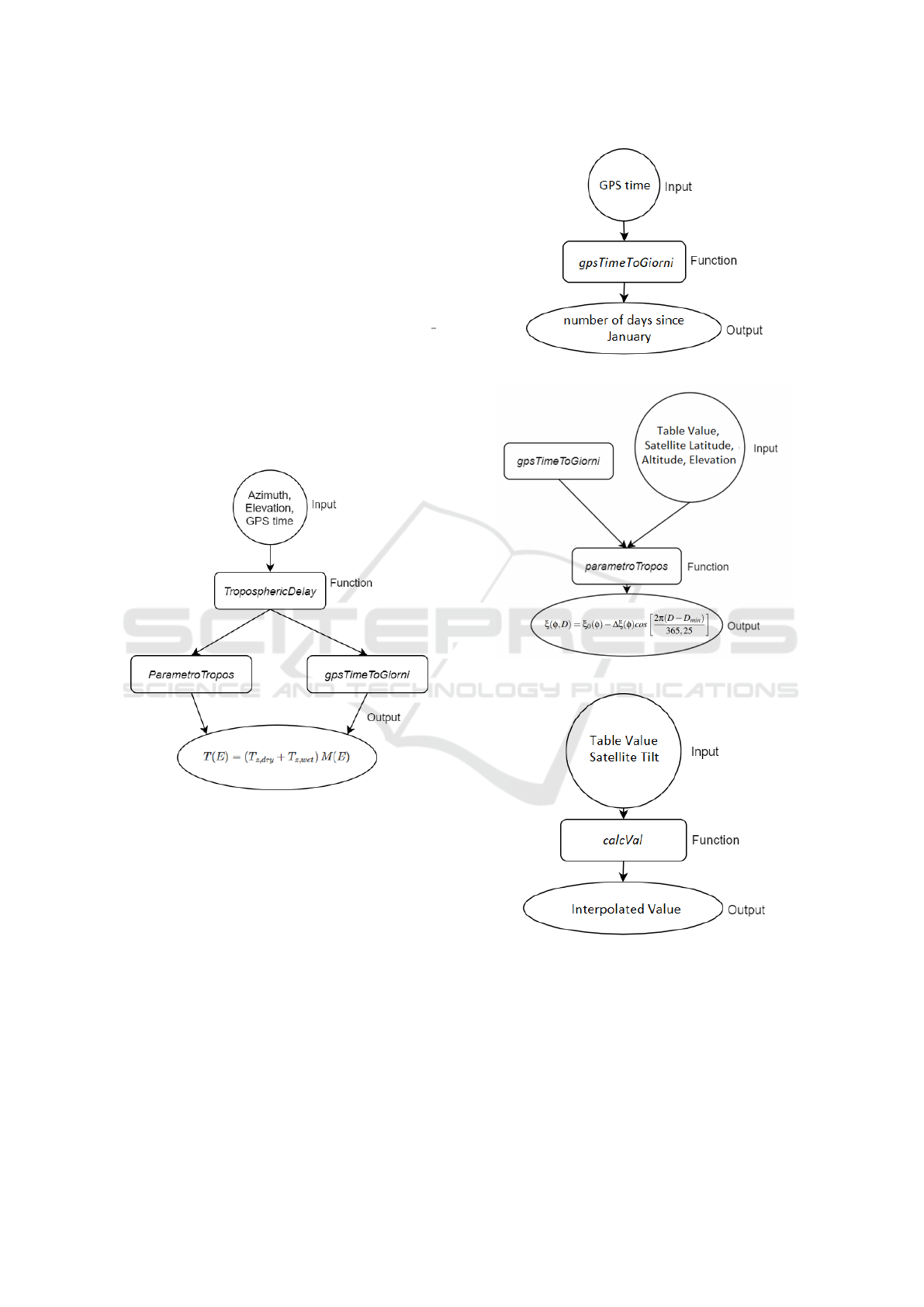
4.1 Implementation of The Model In
The Simulator
In order to develop the model in the considered simu-
lator, three functions have been created in C program-
ming language able to calculate the signal delay, and
then to add it in the pseudorange calculated for each
satellite.
The main method has been called troposphericDe-
lay, it takes as input the g variable of type gpstime t,
which is a struct that represents the GPS time in the
week-seconds format; an array of three double ele-
ments called llh which contains the latitude, longitude
and altitude of the GPS receiver and finally an array
of two double elements called azel, which indicates
azimuth and elevation of the satellite with respect to
the receiver. The diagram is shown in Figure 5:
Figure 5: troposphericDelay function.
The other two functions are: gpsTimeToGiorni
and parametroTropos.
The first has the aim of simply converting the GPS
time from the week-seconds format, to the day of the
year ranging from 1 to 365, the diagrams can be seen
in Figure 6:
The parametroTropos function, see Figure 7, has
the aim of taking the listed values and, on the basis
of the involved parameter such as latitude, satellite
elevation and day of the year, it calculates the correct
value which will then be used in the main method.
The task of the calcVal function (see Figure 8)
used in the parametroTropos function, is to interpo-
late the values taken from the table.
Figure 6: gpsTimeToGiorni function.
Figure 7: parametroTropos function.
Figure 8: calcVal function.
5 PERFORMANCE EVALUATION
In this section the simulation environment is de-
scribed and the experimental results are discussed in
order to show the behavior of the software simulator
with the adding of the proposed model based on the
Tropospheric Collins algorithm.
SIMULTECH 2020 - 10th International Conference on Simulation and Modeling Methodologies, Technologies and Applications
124
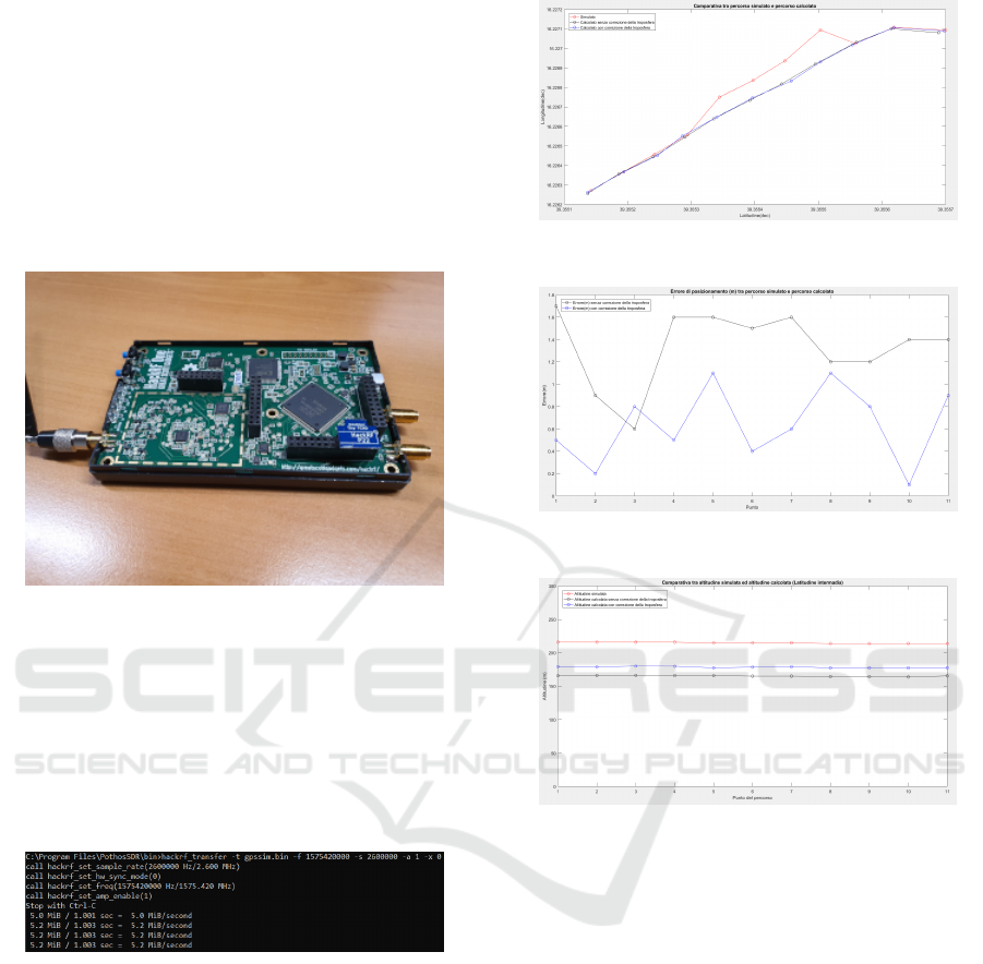
5.1 Simulation Environment
In order to test the changes introduced into the sim-
ulator, an appropriate hardware needs to be used.
The sending device uses the HackRf One card with
the ANT500 antenna and the Nooelec Module Tiny
TCXO 10Mhz module, a very precise oscillator with
very low phase noise. It was chosen from the various
options available for the HackRf One card in order to
use GPS applications (see Figure 9).
Figure 9: HackRf One with its ANT500 antenna and Tiny
TCXO 10Mhz oscillator.
Thanks to Google Earth Pro software, a path was
created consisting of eleven points on the map and
then converted into NMEA format, to be simulated
with the GPS-SDR-SIM software. Subsequently, the
output file of the simulator was transferred in input
to the HackRf One board through the Windows 10
command prompt shown in Figure 10.
Figure 10: Command used to transfer the binary file to the
HackRf One card.
Once the HackRf One hardware is transmitting the
GPS signal, the smartphone’s GPS receiver is used
to make some considerations. Two experiments were
carried out: the first by deactivating the troposphere
correction algorithm and the second one by activating
the implemented algorithm.
5.2 Experimental Results
In the following section some graphics of experimen-
tal results are shown in order to discuss the goodness
of the proposal module implemented in the software
simulator. The line called ”true” path is related to the
real coordinates given in input to the simulator.
Figure 11: Comparison of the two simulated paths with the
’true’ path (intermediate latitude).
Figure 12: Difference in meters between simulated and
’true’ path (intermediate latitude).
Figure 13: Altitude difference between the points of the
simulated and ’true’ path (intermediate latitude).
In Figure 11, it is possible to observe a comparison
between the ”true” path and the two simulated ones:
in red the coordinates given in input at the simulator
are highlighted. These coordinates represent the ref-
erence points from which a GPS receiver should not
deviate too much in order to guarantee a correct GPS
operation. The coordinates calculated by the GPS re-
ceiver are respectively shown in black, with correc-
tion algorithm disabled, and blue, with the correction
algorithm is activated. A big deviation from red line
means a big error by algorithm in calculating the cor-
rect position.
The graphic in Figure 12 shows the positioning
error committed in meters, calculated with respect to
the simulated path.
These two graphics show the results obtained
starting from a path located at an intermediate latitude
and an altitude of about 200 meters above sea level.
The graphic in Figure 13 shows the error commit-
Proposal of a Troposphere Model in Simulation for Automotive Applications
125
ted in calculating the altitude above the sea level by
the receiver.
As it is possible to observe in this Figure the error
on latitude and longitude is on average lower in the
case in which the tropospheric algorithm is activated,
for each point of the considered path.
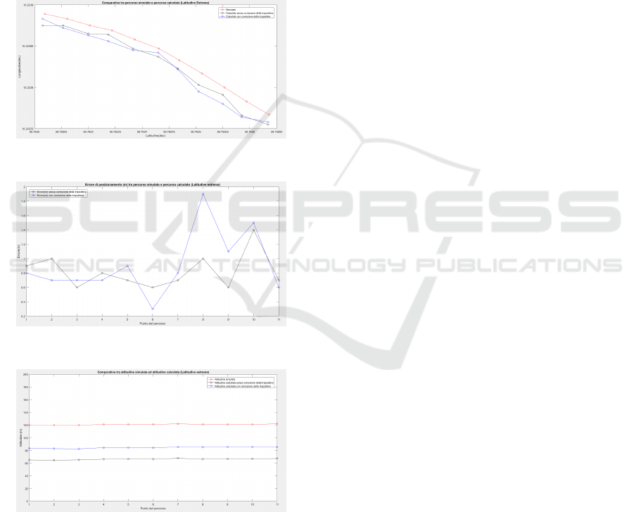
In order to verify the correct operation of the
model in different situations, experiments were also
carried out at extreme and equatorial latitudes. For
that concern the considered path at extreme latitudes,
a route in Norway was chosen by Google Earth Pro
and the coordinates were given in input to the simula-
tor.
Figure 14: Comparison of the two simulated routes with the
’true’ path (extreme latitude).
Figure 15: Difference in meters between simulated and
’true’ path (extreme latitude).
Figure 16: Altitude difference between the points of the
simulated and ’true’ path (extreme latitude).
Figure 14, 15, 16 show the same output parame-
ters illustrated above (in the case of intermediate lati-
tudes) considering the extreme latitude coordinates.
The same consideration made for the previous
case is possible to done also for this new simulative
campaign. It is possible to observe a better behav-
ior of the system when the proposed module is acti-
vated in respect to the one with troposphere module
disabled.
6 CONCLUSIONS
GNSS simulation is a widely used in practice for test-
ing GPS receivers. In this paper, a particular GPS
simulation software with the additional of a novel
Troposperic Collins model has been considered. The
improvement introduced regards the addition of the
delay of the signal transmitted in the form of a pseu-
dorange in order to simulate a very realistic scenario.
The experiments made to test the troposphere model
in the considered simulator were possible thanks to
a special hardware: Hackrf One with its original
ANT500 antenna and a very precise 10MHz nooelec
oscillator. To better evaluate the applied model, three
different tests were carried out at three different lat-
itudes and, as it can be seen from the graphics, the
main improvements in the application of the model
are in the case of intermediate and equatorial lati-
tudes. The results show how the implemented tro-
posperic software module introduces an improvement
in the system guaranteeing better performance in term
of committed errors.
REFERENCES
(2019). Adalm-pluto - active learning module (plutosdr)
- overview. https://wiki.analog.com/university/tools/
pluto.
(2019). ephemeris data information. ftp://cddis.gsfc.nasa.
gov/gnss/data/daily/.
(2019). Hackrf, open source hardware for software-defined
radio. https://greatscottgadgets.com/hackrf/.
Collins, J. P. (1999). Assessment and development of a tro-
pospheric delay model for aircraft users of the global
positioning system.
De Rango, F., Fazio, P., and Marano, S. (2008). Utility-
based predictive services for adaptive wireless net-
works with mobile hosts. IEEE Transactions on Ve-
hicular Technology, 58(3):1415–1428.
De Rango, F., Veltri, F., Fazio, P., and Marano, S. (2009).
Two-level trajectory-based routing protocol for vehic-
ular ad hoc networks in freeway and manhattan envi-
ronments. Journal of Networks, 4(9):866–880.
Deng, C. and Wang, D.-D. (2011). Study and simulation
of digital if gps signals. In 2011 International Con-
ference on Machine Learning and Cybernetics, vol-
ume 2, pages 544–547. IEEE.
Devangavi, A. D. and Gupta, R. (2017). Routing protocols
in vaneta survey. In 2017 International Conference
SIMULTECH 2020 - 10th International Conference on Simulation and Modeling Methodologies, Technologies and Applications
126

on Smart Technologies for Smart Nation (SmartTech-
Con), pages 163–167. IEEE.
Fazio, P., Sottile, C., Santamaria, A. F., and Tropea,
M. (2013). Vehicular networking enhancement and
multi-channel routing optimization, based on multi-
objective metric and minimum spanning tree. Ad-
vances in Electrical and Electronic Engineering,
11(5):349–356.
Fazio, P., Tropea, M., De Rango, F., and Voznak, M. (2016).
Pattern prediction and passive bandwidth manage-
ment for hand-over optimization in qos cellular net-
works with vehicular mobility. IEEE Transactions on
Mobile Computing, 15(11):2809–2824.
Fazio, P., Tropea, M., and Marano, S. (2017). Node re-
routing and congestion reduction scheme for wireless
vehicular networks. Wireless Personal Communica-
tions, 96(4):5203–5219.
Fernandez-Prades, C., Arribas, J., Closas, P., Aviles, C., and
Esteve, L. (2001). Gnss-sdr: An open source tool for
researchers and developers. In Proceedings of the 24th
International Technical Meeting of The Satellite Divi-
sion of the Institute of Navigation (ION GNSS 2011),
pages 780–0.
Fern
´
andez-Prades, C., Arribas, J., Esteve, L., Pubill, D., and
Closas, P. (2012). An open source galileo e1 soft-
ware receiver. In 2012 6th ESA Workshop on Satel-
lite Navigation Technologies (Navitec 2012) & Euro-
pean Workshop on GNSS Signals and Signal Process-
ing, pages 1–8. IEEE.
Fotino, M., Gozzi, A., Cano, J.-C., Calafate, C., De Rango,
F., Manzoni, P., and Marano, S. (2007). Evaluating
energy consumption of proactive and reactive routing
protocols in a manet. In IFIP Conference on Wireless
Sensor and Actor Networks, pages 119–130. Springer.
Frnda, J., Voznak, M., Rozhon, J., and Mehic, M.
(2013). Prediction model of qos for triple play ser-
vices. In 2013 21st Telecommunications Forum Telfor
(TELFOR), pages 733–736. IEEE.
Ghori, M. R., Zamli, K. Z., Quosthoni, N., Hisyam, M.,
and Montaser, M. (2018). Vehicular ad-hoc net-
work (vanet): Review. In 2018 IEEE International
Conference on Innovative Research and Development
(ICIRD), pages 1–6.
Groves, P. D. (2015). Principles of gnss, inertial, and multi-
sensor integrated navigation systems, [book review].
IEEE Aerospace and Electronic Systems Magazine,
30(2):26–27.
Gurtner, W. and Estey, U. (2013). The receiver independent
exchange format.
Hasan, K. F., Feng, Y., and Tian, Y.-C. (2018). Gnss time
synchronization in vehicular ad-hoc networks: bene-
fits and feasibility. IEEE Transactions on Intelligent
Transportation Systems, 19(12):3915–3924.
Hu, Y. (2019). Gnss sdr signal generator implementation
based on usrp n210. In Journal of Physics: Confer-
ence Series, volume 1314, page 012016. IOP Publish-
ing.
Kelley, C., Barnes, J., and Cheng, J. (2002). Opensource
gps open source software for learning about gps. In
ION GPS, volume 2002, pages 2524–2533.
Paakki, T. and Nurmi, J. (2014). Faster than real-time gnss
receiver testing. In International Conference on Lo-
calization and GNSS 2014 (ICL-GNSS 2014), pages
1–4. IEEE.
Paakki, T., Raasakka, J., Della Rosa, F., Hurskainen, H.,
and Nurmi, J. (2010). Tutgnss university based hard-
ware/software gnss receiver for research purposes. In
2010 Ubiquitous Positioning Indoor Navigation and
Location Based Service, pages 1–6. IEEE.
Rao, M. and Falco, G. (2012). How can pseudorange mea-
surements be generated from code tracking. Inside
GNSS Mag, 7:26–33.
Santamaria, A. F., Fazio, P., Raimondo, P., Tropea, M.,
and De Rango, F. (2019). A new distributed predic-
tive congestion aware re-routing algorithm for co 2
emissions reduction. IEEE Transactions on Vehicular
Technology, 68(5):4419–4433.
Santamaria, A. F., Tropea, M., Fazio, P., and De Rango,
F. (2018). Managing emergency situations in vanet
through heterogeneous technologies cooperation. Sen-
sors, 18(5):1461.
Socievole, A., De Rango, F., and Coscarella, C. (2011).
Routing approaches and performance evaluation in
delay tolerant networks. In 2011 Wireless Telecom-
munications Symposium (WTS), pages 1–6. IEEE.
Tsui, J. B.-Y. (2005). Fundamentals of global positioning
system receivers: a software approach, volume 173.
John Wiley & Sons.
Van Sickle, J. and Dutton, J. (2014). Geog 862: Gps and
gnss for geospatial professionals. Penn States Online
Master of GIS.
Zhang, S. and Ji, Z. (2015). A parallel gps satellite posi-
tioning algorithm based on broadcast ephemeris. In
2015 8th International Congress on Image and Signal
Processing (CISP), pages 7–11. IEEE.
Zhou, B., Lee, Y.-Z., Gerla, M., and De Rango, F. (2006).
Geo-lanmar: a scalable routing protocol for ad hoc
networks with group motion. Wireless Communica-
tions and Mobile Computing, 6(7):989–1002.
Proposal of a Troposphere Model in Simulation for Automotive Applications
127
