
Model Predictive Control for Cooperative Insertion or Exit of a
Vehicle in a Platoon
Simone Graffione, Chiara Bersani
a
, Roberto Sacile
b
and Enrico Zero
c
DIBRIS – Department on Informatics, Bioengineering, Robotics and Systems Engineering,
University of Genova, Genova, Italy
Keywords: Longitudinal Control, Vehicle Platoon, Model Predictive Control.
Abstract: Vehicle platooning has a central role in the road management by self-driving or autonomous vehicles (AVs).
The main issues in this context are the agreement of communication and control instructions among vehicles
in order to maintain a safe inter vehicular distance and a specific desired speed according to the planned travel.
This paper proposes a longitudinal Model Predictive Control (MPC) to carry out vehicles’ safe manoeuvres
to let an external vehicle to be inserted in the platoon or alternatively to let a vehicle of the platoon to leave
it. The control strategy considers a cooperative approach where the leader coordinates the exchange of
information with the followers and with the vehicle which notifies its intent to enter (or to leave) the platoon.
All the vehicles are equipped with technologies to monitor their own state in terms of position and speed
while the leader receives, elaborates the data and, by the control process, distributes the optimal control
decisions to the whole platoon. The proposed control algorithm minimizes the tractive forces and the square
deviations of positions and speeds in respect to predefined references. The MPC longitudinal control of the
vehicle, based on a non-linear cinematic model, provides the optimal control values related to the torques to
be applied to vehicles’ acceleration or deceleration in order to perform safe entering and exiting manoeuvring.
The results of the simulations demonstrate the effectiveness of the proposed approach with reduced execution
time.
1 INTRODUCTION
According to literature, an autonomous vehicle (AV)
is defined as a car able to acquire data and information
about the neighbour environment and it may drive for
a prolonged period without human involvement.
To collect the progresses in AV research, SAE the
Automotive Standardization Organization published
the "SAE Information report" that formally defines
six levels of automation for AV, ranging from Level
0 (fully manual) to Level 5 (fully autonomous) (SAE,
2014).
The possibility to perform automated tasks
heavily depends on the capability to get enough
correct and relevant data about the state of the
surroundings. In the context of AV, one of the main
challenges is the possibility to accurately acquire
information about the environment and correctly
a
https://orcid.org/ 0000-0002-5779-9605
b
https://orcid.org/ 0000-0003-4086-8747
c
https://orcid.org/ 0000-0002-9995-1724
represent the external conditions in which the vehicle
operates (Provine et al., 2004).
In order to enhance the safety and the efficiency
of the road traffic management, the AV may assume
a cooperative driving set up. In this case, the AVs may
proceed on the road forming a platoon. The AV
platooning is a research area of the transportation
field, which concerns the strategies to manage a group
of vehicles travelling on the roadway and keeping a
constant inter-distance among vehicles with a specific
shared speed dictated by the safety and traffic
condition. Due to those assumptions, the main
important components which allow the
implementation of a vehicle platoon is the adoption
of the Adaptive Cruise Control (ACC), the use of
reliable vehicle-to-vehicle (V2V) communication
systems, and intelligent control strategies. The ACC
has the function to maintain a constant speed and the
352
Graffione, S., Bersani, C., Sacile, R. and Zero, E.
Model Predictive Control for Cooperative Insertion or Exit of a Vehicle in a Platoon.
DOI: 10.5220/0009970703520359
In Proceedings of the 17th International Conference on Informatics in Control, Automation and Robotics (ICINCO 2020), pages 352-359
ISBN: 978-989-758-442-8
Copyright
c
2020 by SCITEPRESS – Science and Technology Publications, Lda. All rights reserved

control of the inter-distance between vehicles (Zhang,
et al., 2020). The V2V allows communication among
close vehicles according to the IEEE 802.11p
standard in order to share relevant information about
external environment and control (Gonçalves et al.,
2020).
In addition, in real time, the environmental perception
by the AV depends on the different kind of sensors
the vehicle is equipped on. Key components are the
sensors which allow to gain data and, by software
elaboration, to extract crucial information about lanes
marking, traffic signs, identifications of other vehicle
or obstacles on the path (Watzenig D. and Horn M.,
2017). In literature, different intelligent control
strategies have been studied to manage the platoon
behaviour. Recently, special interest has been
dedicated to platooning control when a vehicle
performs a “split” or “join” manoeuvres to exit from
or merge a platoon (Hall, R., & Chin, C., 2005).
Rajamani et al. (2000) proposed the design and
the implementation of lateral and longitudinal control
systems, which work independently, to manage the
request of a vehicle which makes an automated lane
change to exit or enter in the platoon.
Lu et al. (2003) considered longitudinal control
problem for automated vehicle platoon merging with
a model based on the speed of the leading vehicle in
the main lane. Graffione at al, (2020) implemented a
longitudinal control model to optimize the safe inter
vehicular distance among vehicle by operating on the
torques to make positions and speeds close to
reference values
Hussain et al. (2020) proposed a cooperative
Nonlinear Model Predictive Control (NMPC)-based
optimization method for implementing a highway
lane merge of two connected autonomous vehicles.
The authors considered three different scenarios of
merging: the presence of a parallel acceleration lane,
a tapered acceleration lane, and an auxiliary
cloverleaf lane.
In Contet et al. (2007), the authors developed a
multiagent based approach for the vehicle platooning
problem with the possibility to merge new vehicle at
the end of the platoon or exit from the train. In the
proposed approach, each vehicle, implemented as
reactive agent, relates only with the preceding one in
the platoon.
In Amoozadeh et al., (2015), the authors
developed a platoon management protocols, based on
V2V communication combined with longitudinal
control system, referred to specific operations, such
as vehicle entry, platoon leader leave, and follower
leave. The control law is computed by the leader
which transmits to the followers the throttle and/or
brake commands required to track the desired
acceleration.
In this paper, the AV cooperative platoon-driving
problem is tackled focusing on the manoeuvring for a
vehicle which merges or leaves an existing vehicle
platoon coming from an adjacent lane according to
the longitudinal control. The main contribution of this
paper refers to the specific operations, which it
considers in the platooning management and the
application of the MPC approach in order to apply the
state feedback control law. Besides, the objective
function considers different components associated to
the position: the speed, the safe inter-vehicular
distance among vehicles and to the optimal tractive
forces to be applied in order to avoid collision.
2 LONGITUDINAL CONTROL
The proposed control model aims at minimizing the
square divergence among the current value for
position 𝑟 and the speed 𝑟 in respect to the desired
reference values a priori defined in order to maintain
the safe intra-vehicular distance among vehicles in
the platoon. The cost function 𝐽 consists of quadratic
terms with the goal to minimize the use of the tractive
and brake force. Thus, this approach also implies to
decrease the fuel consumption by solving the
optimization problem (2) at each time instant. The
related cost function 𝐽
is defined as in (1).
𝐽
𝜔
𝑥
𝑥
𝐿
𝜔
𝑥
𝑥
𝐷
𝜔
𝑥
𝑟
𝜔
𝑥
𝑟
𝜔
𝑥
𝑥
𝐿
𝜔
𝑥
𝑥
𝐷
𝜔
𝑥
𝑟
𝜔
𝑥
𝑟
𝜔
Δ𝜏
(1)
In eq. (1), the objective function is minimized for the
overall fleet which consists in M vehicles in N time
intervals. The terms 𝑥
and 𝑥
indicate the
longitudinal position and the speed for the i-th
Model Predictive Control for Cooperative Insertion or Exit of a Vehicle in a Platoon
353

vehicle, with i=1..M, at time 𝑘, with k=1..N. The
objective function considers the control application in
the last time interval in the first four terms while, in
the last four terms, it applies the control to the other
time intervals. In (1), 𝐿
and 𝐷
are respectively
the desired safety distance between the vehicles 𝑖 and
𝑖1 and the distance of the vehicle 𝑖 from the leader.
The square deviation of distance among vehicles is
minimized in the first and fifth addenda in (1); the
square error in the distance among the leader of the
platoon and the i-th vehicle appear in second and in
the sixth term for the last time internal N. Also, the
deviation in respect to the reference position and
speed are minimized, respectively, in the third and
fourth terms for the last time interval, in the seventh
and eighth terms for the time horizon. The last term is
related to the minimization of the control variable 𝜏
associated to the torque applied to the vehicle i-th at
the time interval k-th.
The weight parameters 𝜔
, i=1,..,9 allow to weight
the different component in the objective function. The
longitudinal model considers the forces involved
during the acceleration and deceleration of the
vehicle. Both forces are represented by the same
control variable 𝜏 (torque) that can be both negative
(brake) and positive (tractive).
The model is defined as follows:
𝑚𝑥
𝑇
𝑟
𝜏
1
2
𝜌𝐶
𝑥
𝑎𝑏𝑥
𝑚
𝑚𝑔𝑠𝑖𝑛
𝜃
(2)
where
𝑇
is the number of tractive/braking wheels
𝑟
is the wheel radius
𝐶
is aerodynamic drag coefficient for the frontal
area 𝐴 of the vehicle
𝜌 is the air density [1.23
]
𝑎 and 𝑏 are parameters for the rolling resistance
defined as 𝑅
𝑎𝑏𝑉
𝑚 where 𝑉
is the
longitudinal speed
𝑚 is the vehicle mass
𝑔 is the gravity force
𝜃 is the road pitch
The equation (2) can be rewritten in matrix form with
the state 𝑋
𝑥𝑥
.
Given the equilibrium point 𝑋
,
𝑥
,
𝑥
,
considered in the previous time instant, computing
the Jacobian matrix and evaluating them at the point
𝑋
,
, the following linearization of the system may be
obtained:
𝑥
𝑥
1𝑇
01𝑇
𝑏
𝑇
𝜌𝐶
𝑚
𝑥
,
𝑥
𝑥
0
𝑇
𝑇
𝑚𝑟
𝜏
(3)
The overall platoon system is
𝑋
⎣
⎢
⎢
⎢
⎢
⎢
⎢
⎢
⎡
𝑥
𝑥
𝑥
𝑥
⋮
𝑥
𝑥
⎦
⎥
⎥
⎥
⎥
⎥
⎥
⎥
⎤
𝐴
⋱
𝐴
̅
𝑋
𝐵
⋱
𝐵
⎣
⎢
⎢
⎢
⎡
𝜏
𝜏
⋮
𝜏
⎦
⎥
⎥
⎥
⎤
(4)
The finite optimal control problem is defined as
follows:
min
𝐽
𝑋
,Δ𝑈
(5)
𝑠.𝑡. 𝑋
𝐴
̅
𝑋
𝐵
Δ𝑈
(5a)
𝑌
𝐶
̅
𝑋
(5b)
𝑘𝑘,…,𝑘𝑁
Δ𝑈
,
Δ𝑈
Δ𝑈
,
(5c)
𝑘𝑘,…,𝑘𝑁
𝑈
,
𝑈
𝑈
,
(5d)
𝑘𝑘,…,𝑘𝑁
𝑋
,
𝑋
𝑋
,
(5e)
𝑘𝑘,…,𝑘𝑁
where the cost function 𝐽𝑋
,Δ𝑈
in (5) is the
quadratic cost function (1) and the vector Δ𝑈
contains the torque 𝜏
for each vehicle i-th at the
instant k-th.
The constraints (5a) and (5b) linearize the platoon
model in (3) at each time step.
The constraints (5c) - (5e) give more efficiency to
the system imposing minimum and maximum values
for tractive/brake forces to be applied to each vehicle.
These constraints may be also changed during the
simulation according to the platoon state to increase
safety and versatility.
As stated before, the cost function (1) consider the
distance between two consecutive vehicles and from
the leader to ensure safety space interval. In order to
improve this aspect, a three-zone policy is
implemented, which consists of a MPC approach that
ICINCO 2020 - 17th International Conference on Informatics in Control, Automation and Robotics
354
depends on the vehicle distances. The three-zone
policy is usually used also in the rail context for the
European Rail Traffic Management System
(ERTMS) (Bersani at al., 2015).
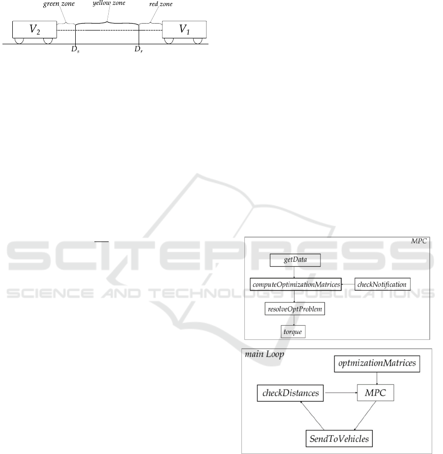
Figure 1: Three-zones distance. The space between two
vehicles is divided into three areas: green, yellow and red.
Each one consists in a different controller approaches.
The green zone represents a safe distance according
to the current speed to avoid collision among vehicles
running the roadway. The yellow zone identifies a
transition zone where the distance has to be
accurately monitored in order to prevent accidents.
Finally, the red zone means that two consecutive
vehicles are travelling too close and they have to
modify their speed in order to establish safe
condition. In the green zone, the distance 𝐷
for the
vehicle i-th is computed as:
𝐷
𝑥
10
𝑆
(6)
where 𝑥
represents the speed of the vehicle and 𝑆 is
a fixed distance from the front vehicle even when the
platoon stops. Equation (6) is a simple way to
compute the distance that lets the vehicle safely
decelerate. Moreover, it overestimates the safety
distance for higher speeds in respect to other standard
techniques such as the “2 seconds driving rule”. This
latter considers that a vehicle should ideally stay at
least two seconds behind the vehicle which precedes
and it is recognized as a valid threshold to estimate
the safety distance (Uribe, D., & Cuan, E., 2018).
This approach does not take into account fuel
consumption, which however may be enhanced by
reducing the distance between cars which favours
aerodynamic interaction. On the other hand, Equation
(6) guarantees road safety and limited consumption
thanks to the MPC which optimizes the torque forces.
Besides the safety distance criterion may be varied
according to the platoon goal.
In the red zone, the distance 𝐷
is computed as:
𝐷
0.25∗𝐷
𝑆
(7)
and it depends on 𝐷
in (6).
3 MODEL PREDICTIVE
CONTROL TO MERGE OR
EXIT THE PLATOON
The MPC approach adopts a receding horizon
approach. For each sample time, the longitudinal
control model defines the optimal matrices that
describe the state of the overall system computing the
safety distance, speed, and acceleration. In the
platooning standard configuration, according to the
measurements received by sensors allocated to the
vehicles, the MPC centralized control, managed by
the leader, check the inter vehicular distances
(checkDistance) and compute the related control
values to be sent to the vehicles’ actuators
(SendToVehicle) in order to maintain the correct
position and speed in the string formation.
The following schema (figure 2.a) represents the
diagram flow of the control system. In the proposed
approach, two different events may happen. In the
first event, the leader may accept the insertion of a
new vehicle, which notifies its intention to merge the
platoon. In the second event, the leader may allow a
vehicle to leave the platoon.
Figure 2: MPC control block diagram. In the top (a), the
MainLoop is relative the basic cyclic operations of data
acquisition – MPC controller – control application. In the
bottom (b), the MPC block specifies that if the controller
receive a specific message checkNotification, it will apply
some changes to the MPC constraints.
In this case, (see figure 2.b), after the notification
of the incoming event, the controller, by the MPC, has
Model Predictive Control for Cooperative Insertion or Exit of a Vehicle in a Platoon
355
to recompute the control values related to the torques,
for each time interval, induced by the longitudinal
control, in order to assure the correct movements of
the vehicles and to permit the new variations in the
platoon configuration.
Figure 3: Control block diagram for merging or exiting
requests.
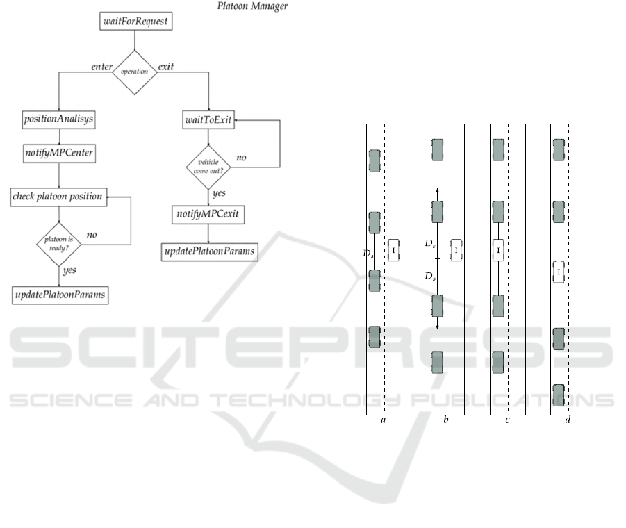
3.1 Merge Manoeuvre
The merge manoeuvre is carried out in three phases:
Request, Insert, Merge. Each phase consists of a
bidirectional communication between the
approaching vehicle and the platoon leader and
among the leader and the followers. A block diagram
that represents the operation flow is shown in the left
side of the Figure 3.
During this manoeuvre, the new vehicle I is
supposed to be equipped with appropriate sensors to
detect obstacles, check its speed and position.
However, if the vehicle is human-driven, it is
supposed that the driver has a console that
communicate to the platoon leader its purpose to be
included in the platoon.
In the first phase, the new vehicle I which is
approaching the platoon, sends a request to the
leading vehicle (waitForRequest) to enter the platoon
also transmitting information about its state such as
speed and position. Then, it waits the response while
remaining in the adjacent lane. Once the leader
receives the request and the data, it decides where
insert the vehicle I in the platoon (positionAnalisys)
by analysing the position and speed of all followers.
According to the acquired data, the leader
communicates the new safety distances, generated by
the MPC controller (notifyMPCenter) to two selected
followers which have to admit the new vehicle. The
distance requested to allow the joint is computed by
doubling the safety distance 𝐷
(equation (5)).
When the correct distance among the two vehicles
which have to admit a new element is reached, the
leader sends a signal to the waiting vehicle I and
confirms the permission. The distance for the entering
manoeuvre is allowed only if it differs from 𝐷
for a
limited error whose threshold is checked by the
checkPlatoonPosition routine.
Figure 4: The three phases of the merge manoeuvre. A new
vehicle approach the platoon (lane 4a), Request phase (lane
4b), Insert phase (lane 4c), Merge phase (lane 4d). The
white vehicle “I” merges the platoon.
In the third phase, the platoon modifies its
configuration according to the new parameters
generated by the controller after the Request phase.
Once the vehicle I is included in the formation, it
communicates to the leader that the manoeuvre was
successfully and it’s ready to follow the platoon rules.
Thus, the system will update the platoon parameters
(updatePlatoonParams) such as the number of
vehicles, their position and the optimization matrices.
At the end of this phase (Merge phase), the vehicle I
is fully included in the platoon and in the centralized
control of the leading vehicle. In case the vehicle I is
too close to a vehicle, checkDistances (figure 2.a) will
detect it and communicate to the MPC to take the
appropriate actions according to the safety green zone
(figure 1).
ICINCO 2020 - 17th International Conference on Informatics in Control, Automation and Robotics
356
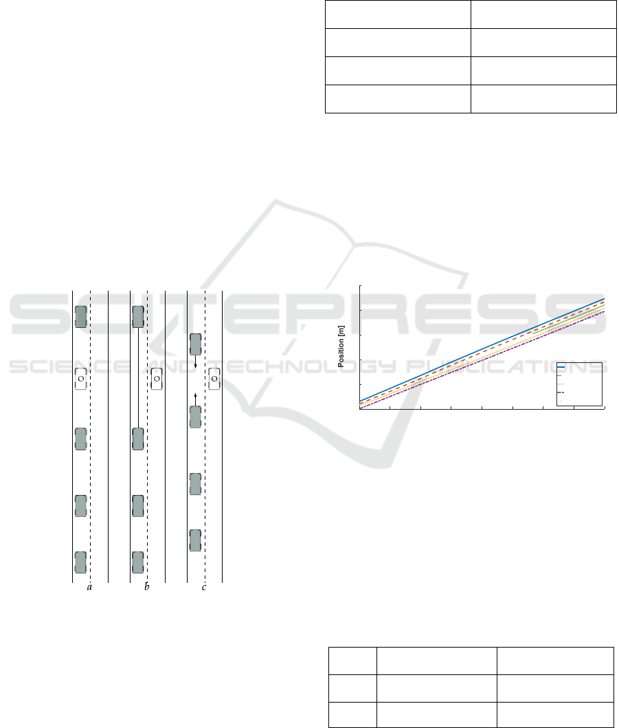
3.2 Exit Manoeuvre
In the exit manoeuvre, a member of the platoon
notifies its desire to leave the formation and to
continue on its own different path. The block
diagram, which describes this phase, is shown in the
right side of the figure 3. As in the Merge manoeuvre,
it is supposed that the vehicle O has a lateral control
that moves the vehicle away from the platoon (the
architecture of the lateral control is not shown in this
paper). Moreover, once it is disconnected from the
leader, the vehicle will use its control system or gives
the full control to the driver to continue its travel.
The first step of the algorithm consists in sending
a request to the leader, asking to exit from the
formation and from the leader control algorithm
(waitForRequest). When the vehicle O has changed
lane (waitToExit), it notifies it to the leader (Exit
phase). The leader will proceed to update the MPC
parameters to disconnect the vehicle from the control
(notifyMPCexit and updatePlatoonParams).
In the last phase, the vehicle is disconnected from
the platoon and the MPC of the platoon compute the
correct control values to its members in order to
define the new right position, speed and safe distance.
Figure 5: The three phases of the Exit manoeuvre. Request
phase (lane 5a), Exit phase (lane 5b), Platoon disconnection
(lane 5c). The white vehicle “O” leaves the platoon.
4 SIMULATIONS
The case study refers to an initial platoon of four
vehicles which cover a rectilinear path with position
and speed reference well defined. The values related
to initial states of the platoon vehicles are displayed
in the Table 1. Simulations have been performed
using MATLAB environment.
Table 1: Initial state value for position and speed for the
platoon vehicles.
Leader
Position: 30 𝑚
Speed: 10 𝑚/𝑠
Follower 1
Position: 20 𝑚
Speed: 10 𝑚/𝑠
Follower 2
Position: 15 𝑚
Speed: 10 𝑚/𝑠
Follower 3
Position: 0 𝑚
Speed: 10 𝑚/𝑠
After some instants from the simulation start, a
new vehicle I approaches the platoon and asks to enter
in the formation. The merge phase for the vehicle I
will be realized by the algorithm described in the
section 3.1.
After the merging phase of the vehicle I, the
vehicle follower 1, called O, will ask to exit the
platoon and it will use the Exit manoeuvre procedure
introduced in the section 3.2.
Figure 6: Platoon position during the Merge Manoeuvre.
Figure 6 shows the longitudinal positions of the
vehicles that are in the platoon. During the merge and
exit manoeuvres, the MPC controller has to satisfy
various constraints. As stated before, the MPC
parameters change in function of the zones where the
vehicles are located. This modification in the platoon
is subjected to the constraints related to the upper and
lower bound for the change rates of the torque.
Table 2: Upper and lower bound for control variables
(eq.5c).
Green
Zone
Δ𝑈
25𝑁/𝑚 Δ𝑈
25 𝑁/𝑚
Yellow
zone
Δ𝑈
15𝑁/𝑚 Δ𝑈
35 𝑁/𝑚
Red Zone
Δ𝑈
25𝑁/𝑚 Δ𝑈
60 𝑁/𝑚
0 5 10 15 20 25 30 35 40
Time [s
]
0
100
200
300
400
500
Platoon positions
Leader
Follower 1
Follower 2
Follower 3
New vehicle
Model Predictive Control for Cooperative Insertion or Exit of a Vehicle in a Platoon
357
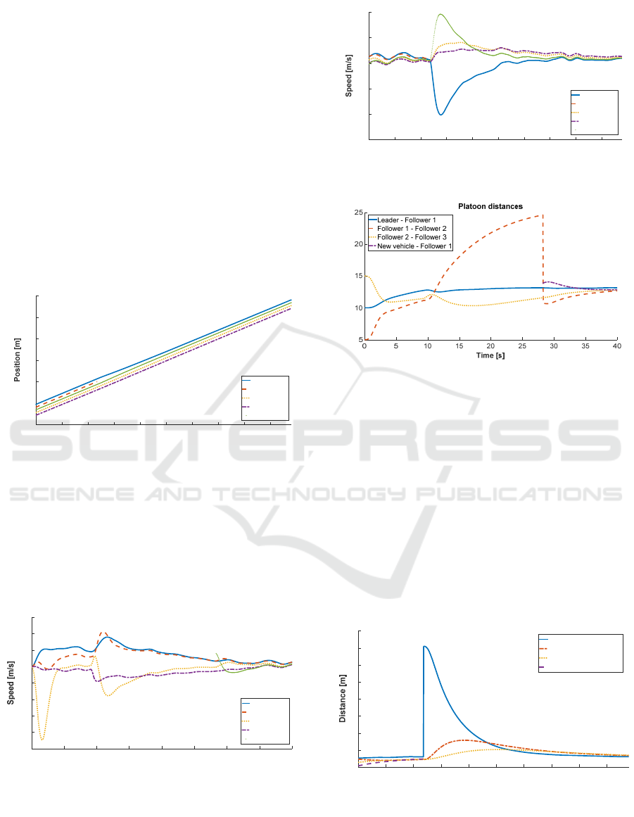
From Figure 6, it is possible to recognize each
phase of the Merge Manoeuvre.
In the time interval [10, 25] the platoon creates
space for the new vehicle, in [25, 30] the new vehicle
enters the platoon between follower 1 and 2 and, from
30
th
interval, the vehicle I is fully included in the MPC
controller.
Besides, it is possible to note that, due to the
initial condition, the follower 2 brakes to increase the
distance from the predecessor since it was in the red
zone and, thanks to the centralized control, the last
follower does not accelerate and waits for the
follower 2 to fill the distances.
In the same time intervals, the Figure 8 and 9
represent the speeds values. They show how each
vehicle adapts its speed to maintain the required
distance (Figure 8).
Figure 7: Platoon during the Exit Manoeuvre. Around 47
seconds, the follower 1 exit the platoon.
On the other hand, in Figure 7, during the exiting
phase, the platoon configuration is shown. Around
second 45, the follower 2 leaves the platoon. In 15 s,
the rear portion of the platoon recomposes the
formation assessing the correct position/speed to fill
the space generated by the exiting vehicle.
Figure 8: Platoon speeds during the Merge Manoeuvre.
Figure 9: Platoon speeds during the Exit Manoeuvre.
Figure 10: Platoon intra-vehicle distances during the Merge
Manoeuvre.
In Figure 10, the variation of the intra-vehicular
distance among vehicles is displayed. When the
merge request comes (at time 10 s), the two groups of
the platoon, in particular between follower 1 and 2,
accelerate and decelerate to create the required space
for the new vehicle I in a short time. In this case, the
leader and the follower 1 increase their speed
(follower 1 up about to 11 m/s) while follower 2 and
3 decreases it (follower 2 until 9 m/s) (See Figure 8).
After the vehicle joints the platoon, the distance
between the follower 2 and I drops since I is entered
the platoon.
Figure 11: Platoon intra-vehicle distances during the Exit
Manoeuvre. When the exit routine occurs, all vehicle
“change” role so the Follower 2 became 1, Follower 3
became 2 and Follower 4 became 3.
35 40 45 50 55 60 65 70 75 80
Time [s
]
300
400
500
600
700
800
900
Platoon positions
Leader
Follower 1
Follower 2
Follower 3
New vehicle
0 5 10 15 20 25 30 35 40
Time [s]
7.5
8
8.5
9
9.5
10
10.5
11
11.5
Platoon speeds
Leader
Follower 1
Follower 2
Follower 3
New vehicle
35 40 45 50 55 60 65 70 75 80
Time [s]
8.5
9
9.5
10
10.5
11
Platoon speeds
Leader
Follower 1
Follower 2
Follower 3
New vehicle
Distance [m]
35 40 45 50 55 60 65 70 75 80
Time [s]
12
14
16
18
20
22
24
26
28
Platoon distances
Leader - Follower 1
Follower 1 - Follower 2
Follower 2- Follower 3
Follower 3 - Follower 4
ICINCO 2020 - 17th International Conference on Informatics in Control, Automation and Robotics
358

In Figure 11, the behaviour can be analysed
during the exit manoeuvre. At time 47, the empty
space left by the follower 1 is rapidly occupied by the
leader and the rest of the platoon with the minimum
effort.
5 CONCLUSION
The paper addresses a centralized approach to model
and control two main important tasks in a vehicle
platoon management. The proposed MPC based
longitudinal control model is consistent to carry out
the specific manoeuvres for a vehicle which intends
to merge or exit the platoon. By a bidirectional
communication pattern, the control variables,
associated to the torque to be applied to the wheels,
have been transmitted, in each time interval, by the
leader to the followers and to the vehicle which
modifies the platoon assessment. In few seconds, the
completion of the manoeuvres are successfully
completed guarantying safety and avoiding
collisions. In a next phase, a lateral and longitudinal
control may be implemented by a robust distributed
control model.
REFERENCES
Amoozadeh, M., Deng, H., Chuah, C. N., Zhang, H. M., &
Ghosal, D. (2015). Platoon management with
cooperative adaptive cruise control enabled by
VANET. Vehicular communications, 2(2), 110-123.
Bersani C., Qiu S., Sacile R., Sallak M., Schön W., “Rapid,
robust, distributed evaluation and control of train
scheduling on a single line track”, Control Engineering
Practice, Vol. 35, pp. 12-21, 2015.
Bersani, C., Guerisoli, C., Mazzino, N., Sacile, R., &
Sallak, M. (2015). A multi-criteria methodology to
evaluate the optimal location of a multifunctional
railway portal on the railway network. Journal of Rail
Transport Planning & Management, 5(2), 78-91.
Contet, J. M., Gechter, F., Gruer, P., & Koukam, A. (2007,
October). Application of reactive multiagent system to
linear vehicle platoon. In 19th IEEE International
Conference on Tools with Artificial Intelligence (ICTAI
2007) (Vol. 2, pp. 67-70). IEEE.
Gonçalves, T. R., Varma, V., & Elayoubi, S. (2020, April).
Vehicle platooning schemes considering V2V
communications: A joint communication/control
approach. In IEEE Wireless Communications and
Networking Conference, WCNC 2020.
Graffione S., Bersani C., Sacile R., Zero. (2020) Model
predictive control of a vehicle platoon. System of
Systems Engineering Conference, SOSE2020, in press.
Hall, R., & Chin, C. (2005). Vehicle sorting for platoon
formation: Impacts on highway entry and throughput.
Transportation Research Part C: Emerging
Technologies, 13(5-6), 405-420.
Hussain, S. A., Shahian Jahromi, B., & Cetin, S. (2020).
Cooperative Highway Lane Merge of Connected
Vehicles Using Nonlinear Model Predictive Optimal
Controller. Vehicles, 2(2), 249-266.
Lu, X. Y., & Hedrick, J. K. (2003). Longitudinal control
algorithm for automated vehicle merging. International
Journal of Control, 76(2), 193-202.
Provine, R., Schlenoff, C., Balakirsky, S., Smith, S., &
Uschold, M. (2004). Ontology-based methods for
enhancing autonomous vehicle path planning. Robotics
and Autonomous Systems, 49(1-2), 123-133.
Rajamani, R., Tan, H. S., Law, B. K., & Zhang, W. B.
(2000). Demonstration of integrated longitudinal and
lateral control for the operation of automated vehicles
in platoons. IEEE Transactions on Control Systems
Technology, 8(4), 695-708.
SAE, Taxonomy and Definitions for Terms Related to On-
Road Motor Vehicle Automated Driving Systems,
J3016, SAE International Standard (2014)
https://www.sae.org/standards/content/j3016_201806/.
Last access April 2020.
Uribe, D., & Cuan, E. (2018). Multi-agent Approach to the
Two-Second Driving Rule. JCP, 13(2), 168-175.
Watzenig D., Horn M. (2017) Introduction to Automated
Driving. In: Watzenig D., Horn M. (eds) Automated
Driving. Springer, Cham.
Zhang, M., He, S., Yang, C., Chen, J., & Zhang, J. (2020).
VANET-Assisted Interference Mitigation for
Millimeter-Wave Automotive Radar Sensors. IEEE
Network.
Zhang, H., Liang, J., & Zhang, Z. (2020). Active Fault
Tolerant Control of Adaptive Cruise Control System
Considering Vehicle-Borne Millimeter Wave Radar
Sensor Failure. IEEE Access, 8, 11228-11240.
Model Predictive Control for Cooperative Insertion or Exit of a Vehicle in a Platoon
359
