
Evolution of Robotic Simulators: Using UE 4 to Enable Real-World
Quality Testing of Complex Autonomous Robots in Unstructured
Environments
Patrick Wolf
a
, Tobias Groll
b
, Steffen Hemer
c
and Karsten Berns
d
Robotics Research Lab, Dep. of Computer Science, TU Kaiserslautern, Kaiserslautern, Germany
Keywords:
Robotic, Simulation, Sensors, Framework, Commercial Vehicle Development.
Abstract:
Robotic simulators are essential for control development since they allow early testing. Additionally, trial
time is tremendously reduced in comparison to a real system. In the recent past, many powerful simulation
systems emerged, offering a high quality and level of realism. Still, those simulators have some shortcomings
concerning the development of complex commercial vehicles that regularly operate within extremely cluttered
and unstructured environments. This paper aims to reduce the gap occurring during the simulation and real-
world testing to increase the expressiveness of robot control software tests.
1 INTRODUCTION
Simulation engines are a powerful tool for the devel-
opment of robotic systems. They allow early testing,
design and sensor optimization, plus improved con-
troller development before tests on the physical plat-
form are performed. However, there exists a gap be-
tween testing in simulation and the real world. In the
past, complex, relevant features for robot perception
could not be completely modeled by the simulator
due to the versatility of environments. This is espe-
cially true for the development of autonomous com-
mercial vehicles which have specialized supplements
and kinematics for task fulfillment. However, the
consideration of specialized sensors, sensing distur-
bances, and the environment is essential for success-
ful control development. With the Unreal Engine 4
(UE 4), a suited framework for photorealistic render-
ing of complex scenes at the real-time performance is
available. In recent literature, many UE 4-based sim-
ulators have been proposed. Unfortunately, they do
not explicitly address the requirements for complex
commercial vehicles and sensing errors in the qual-
ity required to reduce the simulation and real-world
testing gap.
The following contribution targets the integration
a
https://orcid.org/0000-0003-2740-7655
b
https://orcid.org/0000-0002-6214-9842
c
https://orcid.org/0000-0002-8141-3434
d
https://orcid.org/0000-0002-9080-1404
of the Unreal Engine 4 into the middleware Finroc.
Based on the UE 4-Finroc-API, sensors can be mod-
eled in a more realistic way to include necessary char-
acteristics that affect the robot’s navigation and per-
ception. Robot control behavior can be tremendously
improved through the consideration of such effects.
Also, the risk of tailoring a control approach towards
(simulation) specific data decreases.
Sect. 2 describes state of the art and evolution of
robotic simulators followed by a description of the
UE 4-Finroc interface (Sect. 3). Sensors and virtual
robot setup is addressed in Sect. 4. Sect. 5 targets spe-
cialized actuation. Finally, two applications examples
are provided (Sect. 6) and a summary and conclusion
follows (Sect. 7).
2 RELATED WORK
Robotic simulators are a common tool for control de-
velopment. Depending on the application field, there
are different requirements for the simulation. Accord-
ing to (Goodin et al., 2018), these can be grouped into
three major fields:
Development Environments focus on the basic
physical modeling and environment interaction.
Test Environments detailed representation of the
environment, more realistic physics and sensor
data modeling.
Empirical/semi-empirical simulators application
tailored highly realistic physics or sensor data.
Wolf, P., Groll, T., Hemer, S. and Berns, K.
Evolution of Robotic Simulators: Using UE 4 to Enable Real-World Quality Testing of Complex Autonomous Robots in Unstructured Environments.
DOI: 10.5220/0009911502710278
In Proceedings of the 10th International Conference on Simulation and Modeling Methodologies, Technologies and Applications (SIMULTECH 2020), pages 271-278
ISBN: 978-989-758-444-2
Copyright
c
2020 by SCITEPRESS – Science and Technology Publications, Lda. All rights reserved
271

Simulation frameworks belonging to the first category
are exemplary SimVis3D (Wettach et al., 2010) or
Gazebo (Aguero et al., 2015). Both feature a 3D sim-
ulation including a physics and render framework as
well as a control API. SimVis3D, uses the Newton
Dynamics physics engine and Coin3D for visualiza-
tion while Gazebo relies on the Open Dynamics En-
gine and initially OpenGL Utility Toolkit (GLUT) but
nowadays OGRE. Also, V-REP (Freese et al., 2010)
is a multipurpose robot simulator that supports nu-
merous languages and controllers. The user inter-
face enables a simple construction of a robotic sys-
tem and offers a default sensor suite. Yet, there are
limitations when it comes to bigger environments and
photo-realistic textures. As an example of second
and, to some extent, the third category, Virtual Au-
tonomous Navigation Environment (VANE) (Goodin
et al., 2017) can be mentioned. Its focus is on mili-
tary, off-road unmanned ground vehicles (UGV) and
therefore puts strong efforts in material (reflections),
weather (sun/rain), dust/haze (atmosphere), and vege-
tation simulation. Similarly, USARSim (Carpin et al.,
2007), an urban search and rescue simulation build on
the commercially available Unreal Engine 2.0, is of
restricted use.
Unreal Engine 4 (UE 4) started to offer photo-
realistic rendering, an open-world design, and level
of detail processing for free in academic applications
in 2014. The prominent CARLA (Dosovitskiy et al.,
2017) describes itself as a “simulator for autonomous
driving research”. At its core, UE 4 does the main
physics simulation and rendering work whereas the
framework provides a whole lot of tools and resources
for testing autonomous car driving in urban scenarios.
This includes simulated sensor suites, UE 4 content
such as vehicles and urban maps as well as support for
loading OpenDrive format for map generation. Sim-
ilarly, AirSim (Shah et al., 2017), Sim4CV (M
¨
uller
et al., 2017), and Flightgoggles (Guerra et al., 2019)
were initially developed for the aim to test computer
vision algorithms within the field of drone/UAV ap-
plications and are extended for autonomous driving.
Pavilion presented by (Jiang and Hao, 2019) focuses
on combining UE 4 with an interface for ROS using
standard ROS messages, yet using no separate bridge
application and resolving the binary incompatibility
due to Run-Time Type Information (RTTI) and C++-
exceptions.
3 SIMULATION FRAMEWORK
Multiple software components are applied to imple-
ment and test robotic control systems in simulated
environments. Supplementary to a robot control soft-
ware framework, a simulation engine allows the mod-
eling of robots and environment to simulate physical
properties of those.
3.1 Finroc
The Finroc framework for robot control provides a
powerful suite for the development of robot control
systems (Reichardt et al., 2013). The central con-
cept is the decompostion of functionality into mod-
ules. A Finroc program is called part while data struc-
tures for data exchange are ports. They provide an
abstraction from the actual communication technol-
ogy, as TCP. Through information hiding, the com-
munication stack can be easily exchanged. Finroc of-
fers inter-network communication as well as shared
memory-based technologies for lock-free and zero-
copy data exchange. The Finroc-UE 4 simulation uses
Finroc data ports for communication.
3.2 Unreal Engine 4
An important criterion for selecting the best-fitted
simulation engine is a high performance in visual-
izing outdoor landscapes and representing vehicles
physically correct. Gaming engines are especially
suited for this purpose since they perform outstand-
ingly in representing very realistic environments and
have feasible realtime simulation capabilities. UE 4
offers these features in a powerful way and is there-
fore selected as simulation. Further, UE 4 provides
good support for the development of own content and
extensions. It provides multiple possibilities for soft-
ware modules development using an extensive C++
API and BLUEPRINT system. Physical effects use
NVIDIA PhysX which allows fast calculations on a
GPU. Further, the material and rendering system en-
ables a realistic visualization of the environment.
The overall performance of a robot’s sensor is
strongly influenced by the sensing quality. Conse-
quently, it is necessary to generate appropriate data
to simulate such sensors. Often applied systems are
visual sensors like cameras or laser-scanners which
especially benefit from simulation realism. UE 4 en-
ables data generation that has similar quality to the
real-world based on realistic-looking environments.
3.3 Interface Plugin
Finroc and UE 4 share data for the transmission of
sensor readings and exchange of control commands
for simulated actuators. An UE 4-Finroc plugin pro-
vides an API for both software systems using the C++
SIMULTECH 2020 - 10th International Conference on Simulation and Modeling Methodologies, Technologies and Applications
272

Figure 1: UE 4-Finroc interface and data exchange.
programming language. Port functionality of Finroc
is loaded by UE 4 due to its modular structure via a
shared object file.
The plugin provides specialized UE 4 actor com-
ponents that wrap Finroc ports (Fig. 1). Those inter-
face components assert data type compatibility and
can be attached to any actor. C++ classes and
BLUEPRINTS in the UNREAL EDITOR can send or
receive data from Finroc ports using the publish and
get mechanisms. Continuous data updates can be re-
alized using the actor tick function. Ports transmit
data of arbitrary C++ data types. To ensure data com-
patibility and reduce complexity, a generic UBUFFER
type is used for communication together with trivial
types as INT, BOOL or FLOAT. Complex data as im-
ages use this buffer to transmit a byte stream. The
API on Finroc side transforms the actual data to the
standard Finroc data type.
Through this communication system, simulation
and real hardware abstraction can be easily ex-
changed. Optimally, no control behavior change can
be observed after an abstraction layer exchange.
4 SENSORS
Robot control behavior strongly depends on the
equipped sensors and their respective data quality.
Therefore, apart from insufficient modeling of kine-
matics or robot actor’s characteristics, the absence
of sensor data characteristics prevents realistic robot
control simulations. Thereby, it is not necessarily re-
quired that the error is an exact replication of the real-
world error but a simulated sensor should have at least
the same error characteristic and quality to test the im-
pact on control.
4.1 Localization Systems
Robot localization systems determine the position and
orientation within an environment. Localization er-
rors play a critical role in task execution and robot
safety.
Interial Measurement Units. Inertial measure-
ment units (IMU) provide acceleration readings
around every translational and rotational axis of a
robot. Additionally, the 3D orientation is usually
available. IMU data is often prone to integration er-
rors over time. Also, a magnetometer may react to
(ferro-)magnetic objects nearby as the vehicle’s frame
or (electro-magnetic) motor currents.
The simulated IMU accesses the physic model of
the UE 4 robot actor and reads the linear velocity vec-
tor ~v as well as the angular accelerations. The ve-
locity is derived using the tick duration ∆t to retrieve
the linear acceleration ~a = ~v · ∆t
−1
. Next, the stan-
dard gravity is applied to simulate earth gravity. The
robot’s rotation can be directly accessed by the IMU
actor. Depended on the real IMU model, drifts or slips
over time can be added in a preprocessing step to ap-
proximate the physical sensor’s quality. This prevents
that reintegrated velocities correlate too strictly with
the relative velocity of the body to which the IMU is
mounted.
Odometry. Odometry data uses the kinematic
model of the robot to determine the robot’s motion
based on the wheel velocities and steering angle. It
is not sufficient to model odometry data by reading
the robot’s linear velocity and steering angle directly
from the physics since wheel slip is not considered.
Therefore, UE 4 odometry sensors access the
skeletal mesh of the robot and read the angular ve-
locities of the corresponding wheel bones. The calcu-
lation to determine the robot’s velocity, curvature, and
slip angle depends on the kinematic of the robot. The
values are determined in the robot specific kinematic
model within a preprocessing step.
Global Navigation Satellite Systems. A common
global localization sensor is the Global Navigation
Satellite System (GNSS). GNSS systems are heavily
affected through the environment as shadowing which
should be regarded by simulation. The visible satellite
constellation is described as the dilution of precision.
The horizontal (HDOP), vertical (VDOP), and posi-
tion (PDOP) dilution of precision calculation depends
on the geometric constellation of satellites (Santerre
et al., 2017). To save computational power, the DOP
computations of the simulated GNSS are approxi-
mated from the satellite count only. An exponential
regression was used to find constants for the approx-
imation function based on a real-world GNSS data
set. The data set was collected using a GatorX855D
robot equipped with a Starfire 3000 RTK and an u-
blox NEO-7P GNSS receiver. Due to the higher pre-
cision, the Starfire served as ground truth. The robot
Evolution of Robotic Simulators: Using UE 4 to Enable Real-World Quality Testing of Complex Autonomous Robots in Unstructured
Environments
273
traveled a closed track at the TUK campus of approx-
imately 500 m. The aim was the determination of
effects through occlusions through buildings and the
impact on the DOP value.
The approximated values for HDOP, VDOP, and
PDOP are computed as follows
DOP = max
ba
i
· rn
sat
i
· 100 + 0.5c
100
,1.02
(1)
where sat denotes the number of visible satellites and
i stands for the respective DOP. The experimentally
determined constants for the exponential regression
are depicted in Table 1 and are incorporated by the
simulated GNSS receiver.
The GNSS noise affecting latitude and longitude
depends further on the visible satellite configuration.
The amplitude of the GNSS error ε
i
is computed as
ε
i
= a
i
· rn
sat
i
(2)
where i ∈ {HDOP, VDOP, PODP} corresponds to the
previous readings. The amplitude value is multiplied
with randomly generated noise generated from the
GNSS base precision as stated in the corresponding
data sheet. Finally, it is added respectively to the lati-
tude, longitude, and altitude.
The number of visible satellites is split into the
general direction of visibility (north, south, east, and
west). The GNSS fix category is
fix =
No Fix sat ≤ 1
Bad Fix 1 < sat ≤ 2
2D Fix 2 < sat ≤ 3
3D Fix sat > 3
(3)
In the case that at least a single quadrant contains no
visible satellites, the 3D Fix degrades to a 2D Fix. It
follows, PDOP = 0 for 2D fixes. Additionally, DOP
values are not available for No Fix or Bad Fix.
The GNSS simulation realization uses raytracing
to determine the visibility of the receiver. Hereby,
a satellite manager spawns satellites which are lo-
cated and distributed above the scene. Each simulated
GNSS receiver accesses the satellite manager to get
a reference on the available satellites. Each receiver
performs a ray trace on each satellite to determine vis-
ibility. A coding example is given in Alg. 1.
Table 1: Experimentally derived constants of the DOP ap-
proximation though exponential regression.
Constant Value Constant Value
a
HDOP
5.59474 rn
HDOP
0.854736
a
VDOP
10.2524 rn
VDOP
0.858869
a
PDOP
2.63625 rn
PDOP
0.967947
Algorithm 1: Code snippet to determine satellite
visibility with UE 4 GNSS receiver.
1 FHitResult hitresult(ForceInit);
2 FCollisionQueryParams ft par =
FCollisionQueryParams(FName(TEXT("FireTrace")),
true, this);
3 ft par.bTraceComplex = true;
4 bool hit = GetWorld()->LineTraceSingleByChannel(
hitresult, satellites[i]->GetActorLocation(),
this->GetActorLocation(), ECC Pawn, ft par);
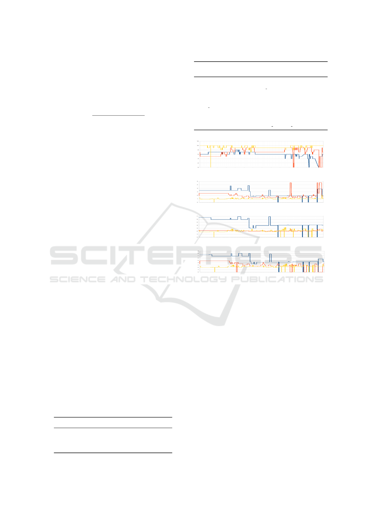
(a) Satellite count.
(b) HDOP.
(c) VDOP.
(d) PDOP.
Figure 2: Real-World data plotted against the traveled dis-
tance (blue: Starfire 3000 RTK, yellow: u-blox NEO-7P)
with comparison to the reenacted simulation trial on the vir-
tual TUK campus (red: simulated GNSS).
For validation purposes, the simulated GNSS has
been compared to the real world GNSS signals.
Therefore, a simulated data set was recorded on the
UE 4-TUK campus by replicating the initial drive.
The simulated number of GNSS satellites and DOP
values are plotted against the robot position as de-
picted in Fig. 2. It can be observed that the satellite
count of both real-world GNSS systems (blue Starfire
3000 RTK, yellow u-blox NEO-7P) differ from each
other even if there are at a similar location on top of
the robot. However, the simulated signal (red) has a
similar quality as the real systems. This is also vis-
ible for the DOP results where the simulation signal
resembles the u-blox receiver.
4.2 Vision-based Sensors
It can be distinguished between different classes of
vision sensors like cameras, depth cameras, or laser
SIMULTECH 2020 - 10th International Conference on Simulation and Modeling Methodologies, Technologies and Applications
274
scanners. Effects on the vision system as exposure, or
dust can be easily modeled using post-processing and
particle systems.
Generic Cameras. Simulated cameras utilize the
UE 4 render pipeline. Cameras properties as field of
view or resolution are defined in the respective camera
component and the corresponding render target of the
engine according to the sensors data sheet. The sim-
ulated camera enqueues a non-blocking render com-
mand and publishes the data when the rendering pro-
cess is finished. Therefore, it is possible to use a large
set of cameras in complex scenes without slowing the
tick system. Specialized cameras can be easily imple-
mented by inheriting the base class and adapting the
respective properties and post-processing materials.
The properties of the camera can be adapted through
the control software, for instance, updates can be trig-
gered by the perception system of the robot.
Stereo and Depth Cameras. Stereo or depth cam-
eras provide distance information in addition to color
data. A common approach to simulate distance sen-
sors is reading the depth buffer of the simulation ren-
der engine. However, stereo cameras rely on the
matching of a calibrated image pair. The match-
ing process introduces a backward distortion of the
point cloud resulting from the image disparity. Re-
flections, insufficient texture, and disturbances of the
device’s lenses typically cause spurious obstacles or
gaps within point data. Moreover, uncertain obstacle
boundaries are common.
A more lifelike sensor version, but also computa-
tionally more expensive, uses semi-global matching
of two rendered images (Hirschm
¨
uller, 2008) as de-
picted in Fig. 3. Accordingly, two generic camera ac-
tors with parallel arranged lenses start a simultaneous
rendering of the scene. The resulting image pair has
to be rectified and matched.
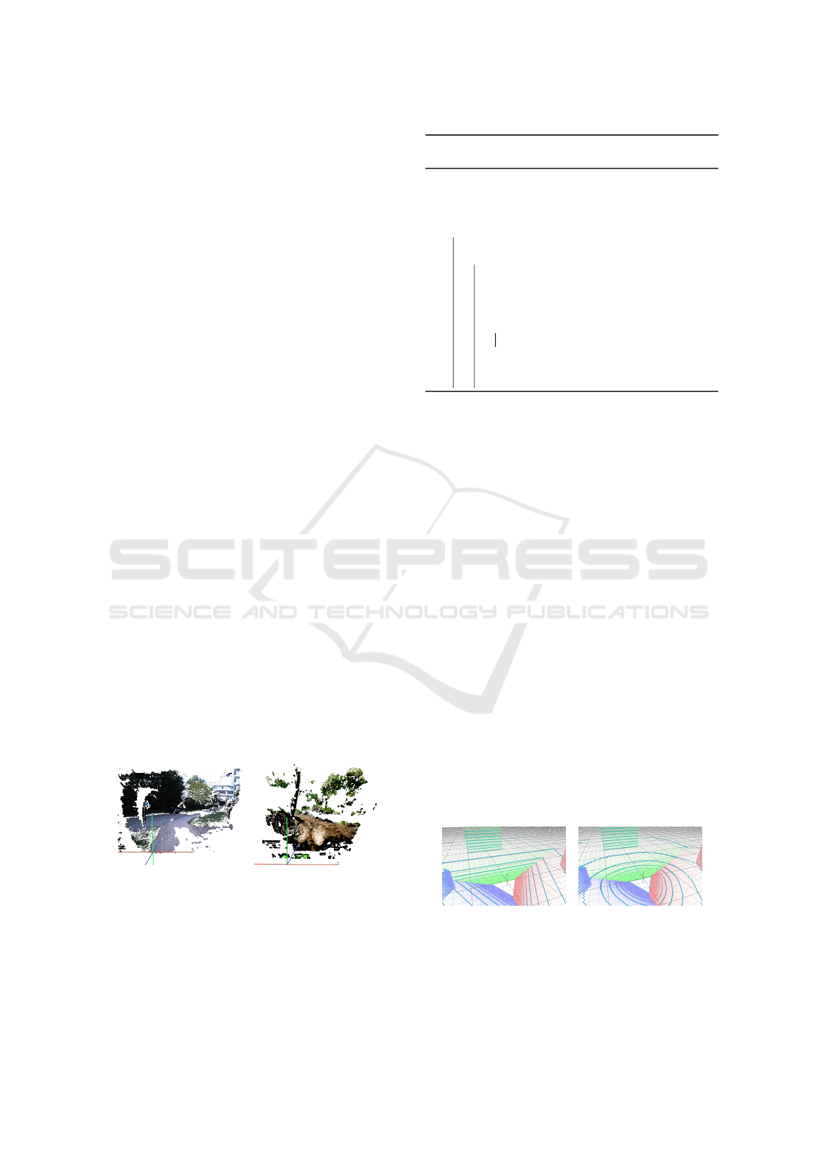
(a) Real data. (b) Simulated data.
Figure 3: Real and unreal stereo colored point cloud data
with characteristic stereo matching disturbances.
360-Degree Cameras and Laser Scanners. A
360-degree camera can be realized using multiple
generic camera actors. An orientation change is ap-
Algorithm 2: Pseduo code for hyperbolic distortion
of pixel mapping.
Data: render resolution, laser resolution, beam angles
Result: index mapping
1 determine pixels per beam;
2 determine zero angle pixel;
3 for y ∈ vertical laser resolution do
4 determine distance to zero pixel;
5 for x ∈ horizontal laser resolution do
6 hyperbola = calculate hyperbola (
7 asymptote a → distance to zero pixel
8 asymptote b → horizontal render resolution / 2
9 value → − horizontal render resolution / 2 + x);
10 if distance to zero pixel negative then
11 hyperbola = −hyperbola;
12 re-apply zero angle pixel offset to hyperbola;
13 limit hyperbola to pixel bounds;
14 index mapping(x,y) = (x, hyperbola);
plied to scan a full cylinder or respectively sphere.
Based on the UE 4 camera’s maximum FOV of 170
◦
,
three cameras are required to record a 360-degree im-
age.
In contrast to stereo cameras, lidar sensors can be
implemented using depth rendering. Since the lidar’s
precision, and range is higher than these of a stereo
camera no additional introduction of distortions is re-
quired. Simulated particle effects as dust affect the
engine’s depth buffer which corresponds to a real sen-
sor behavior that reacts strongly to environmental par-
ticles and provides spurious readings.
Often, the vertical opening angle is smaller than
the horizontal angle since the laser count is often
rather small (e.g. 16 − 128 lines). A lower vertical
resolution has to be regarded by skipping lines of the
depth image which has typically a higher resolution
due to quadratically rendered pixels. Skipping lines
under the consideration of the horizontal offset gener-
ates a linear rendered image (Fig. 4a). This rendering
is feasible for some lasers as single-line lasers. In the
case of a rotating laser scanner, a hyperbolic distor-
tion can be observed in the point cloud due to the po-
lar coordinate mapping of the rotating beam. This dis-
tortion can be approximated using a hyperbolic point
mapping in the dense depth image (Fig. 4b). The hy-
(a) Linear. (b) Hyperbolic.
Figure 4: 360 degree depth camera using three render tar-
gets (red, green, purple blue). Laser data with a lower ver-
tical resolution can be approximated (blue). The laser’s ro-
tation is approximated using hyperbolic distortions.
Evolution of Robotic Simulators: Using UE 4 to Enable Real-World Quality Testing of Complex Autonomous Robots in Unstructured
Environments
275
perbolic equation is given with
h =
r
a
2
+
x
2
· a
2
b
2
. (4)
The resulting pixel mapping is explained in Alg. 2.
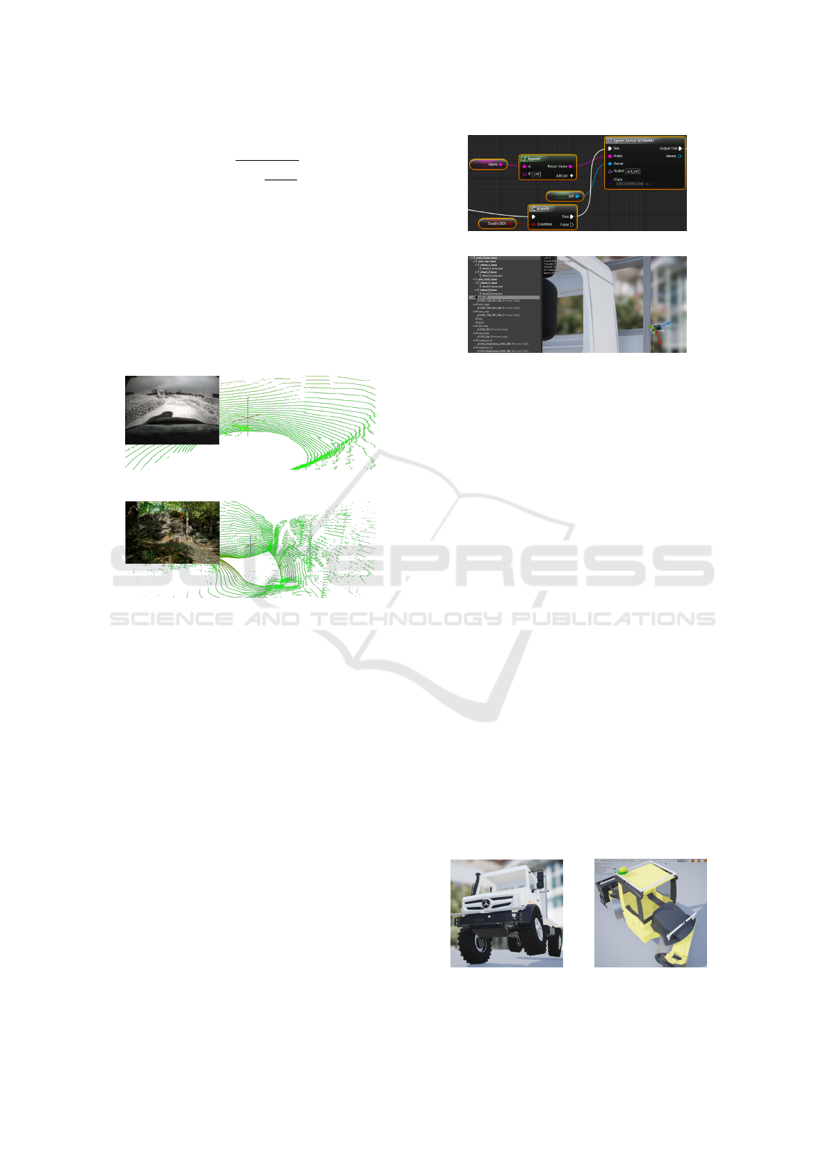
The simulated point cloud approximates well to
real point cloud data as it can be seen on the exam-
ple of a simulated Velodyne HDL-32E laser scan-
ner using 32 laser lines (Fig. 5). However, it can
be observed that the data close to the scanner built
a triangle-shaped point pattern based on the render-
ing using multiple camera frustums. This effect can
be avoided if needed using ray-based techniques or
through vertical oversampling of the depth images.
(a) Real point cloud.
(b) Simulated point cloud.
Figure 5: Real and simulated Velodyne HDL-32E point
clouds. The scanner has 32 scan lines with a vertical field
of view of 41.33
◦
and vertical offset of −20
◦
.
4.3 Robot Setup
The UE 4 editor is used for robot setup and sensor
placement. Therefore, sensor sockets are added to
the robot’s skeletal mesh. This allows a constructive
approach based on the mesh and therefore real sizes
and shape of the robot. Accordingly, optimum sen-
sor positions can be determined and the correspond-
ing best mounting position on the robot tested. De-
pending on the mesh quality, unconsidered effects as
obstructions through parts of the vehicle, blind spots,
or small building spaces can be early detected.
The robot spawns the sensor within the main
blueprint at the begin of play. Therefore, it uses a
macro blueprint for spawning and attaching the sen-
sor actor to the desired sensor socket (Fig. 6a). The
socket can be adapted in the robot’s skeleton and the
physical robot may use the layout which performed
best in the preliminary tests (Fig. 6b).
(a) Spawn sensor on socket.
(b) Skeleton and virtual sensor on socket.
Figure 6: Virtual sensor placement to determine the best
mounting position.
5 ACTUATORS
Besides the recognition of the environment, au-
tonomous systems interact through controlling the
motion or actuators of associated vehicles. Hereby,
degrees of freedom should be similar to the real ma-
chine. Some vehicles, particularly commercial or spe-
cialized vehicles, used some unique configurations.
5.1 Driving Kinematics
Commercial vehicles often consist of special driv-
ing kinematics which cannot be realized by a stan-
dard Ackermann steering. Therefore, the use of the
wheeled vehicle template class in UE 4 is strictly lim-
ited. Exemplary, an Unimog U5023 special truck has
an axle shrinking of 30
◦
front axis, and 15
◦
rear axis,
portal axles for higher ground clearance, differential
locks, 14 gears, and a tire inflation system to adapt
friction during navigation (Fig. 7a). For simulation,
additional joints were built into the skeleton of the ve-
hicle to model the additional properties. The axle can
rotate using a joint and two springs for stabilization.
The adaptable tire friction is simulated by changing
the tire’s friction parameters during runtime. Gears
and differential setup is used from the UE 4 vehicle
(a) Axle shrinking. (b) Pivot steering.
Figure 7: Ackermann-based special driving kinematics.
SIMULTECH 2020 - 10th International Conference on Simulation and Modeling Methodologies, Technologies and Applications
276
base class and parameterized according to the U5023
data sheet and adapted during runtime through Finroc
ports.
In contrast, the autonomous tandem roller BW 174
is controlled by a pivot-steering (Fig. 7b). Therefore,
a custom double Ackermann steering class was cre-
ated by implementing the bicycle kinematics. It ac-
cesses the steering joints and controls the respective
angular velocities. Supplements as edge cutters or
chip spreaders are controlled through the skeleton of
the vehicle.
5.2 Complex Body Actuation
To test control software for excavation applications,
a simulation model of an excavator requires to have
similar characteristics as the real machine. It is not
necessary to rebuild the excavator dynamics com-
pletely realistic, but it has to fit the used control al-
gorithms.
Parallel Kinematic Chains. An excavator arm has
a very characteristic kinematic. It consists of seg-
ments that are moved with hydraulic cylinders. This
hydraulic system is connected to the moving segment
in an own kinematic chain which is placed in parallel
to the actual segment (Groll et al., 2015). The excava-
tor arm is modeled as a bone structure of the physical
enabled skeleton mesh. It is organized as a tree struc-
ture and single parts can be connected by moveable
joints. For each part of the excavator arms kinematic
structure, a bone is created. Each bone has a body that
is used as a representation for the weight including
the weight distribution to allow a physical solid-body
simulation. All of the main elements of the excavator
arms are connected with a revolute joint to the previ-
ous one. A parallel kinematic chain is added to each
of the main parts which include the hydraulic drives to
move the appropriate body part. In all of these chains,
the hydraulic cylinder is modeled as a prismatic joint
with an enabled drive. Fig. 8 provides an overview to
the crowd kinematics.
It starts with the boom body at which the main
crowd’s body is connected with a revolute joint. To
Figure 8: Configuration of the hydraulic actuator.
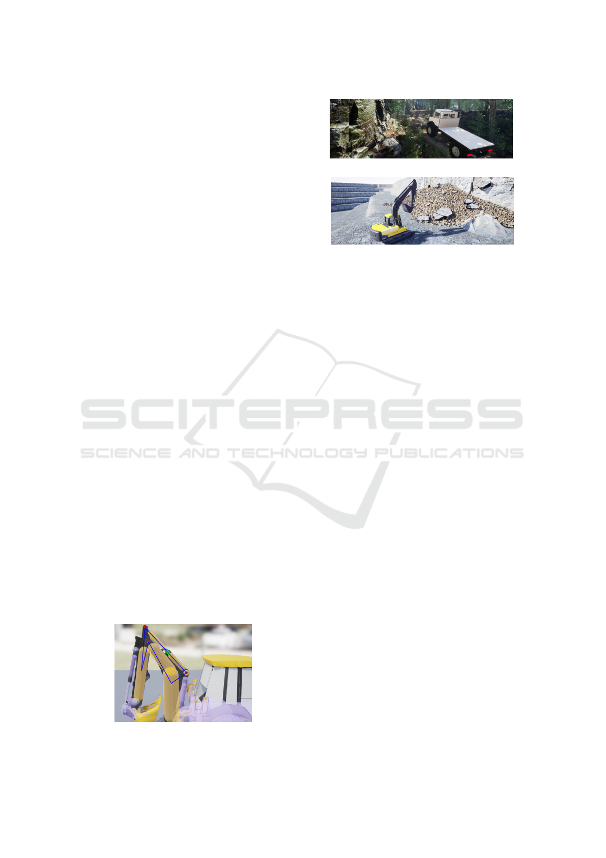
(a) Autonomous off-road navigation.
(b) Autonomous excavation.
Figure 9: Applications of commercial vehicle robots.
this body the piston rod is linked by another rotational
joint. Following by the base of the cylinder which is
connected by the driven prismatic joint. The last part
of the chain is built by a spherical body which is used
to connect the hydraulic chain back to the boom.
Hydraulic Actuators. Hydraulic cylinders produce
a movement that has a velocity proportional to the
flow rate of the hydraulic oil generated by the pump
system. This can be influenced by the opening of
a valve which is normally controlled by commands
given from the joysticks. In the autonomous control
system these joystick commands are generated by the
control software. A spring-damper system is used for
generating the forces which are used by the drives to
move the connected bodies. It uses the velocity error
as well as the position error to calculate the force:
force = spring ∗ (targetPosition − position)+
+ damping ∗ (targetVelocity − velocity) (5)
Besides the target velocity, a target position as
control input for the drive is needed as well. To
deliver this value a control system is added to the
hydraulic drive which calculates the actual expected
position depending on linear velocities and the time
which has passed.
6 APPLICATION & SCENARIOS
The presented simulation framework is used in vari-
ous scenarios and applications. In the following, two
examples are provided which benefit strongly from
the simulation.
The first example is the autonomous Unimog
U5023 (Fig. 9a). The focus of this robot is safe
and reliable off-road driving inside cluttered environ-
ments. UE 4 provides very realistic environments that
Evolution of Robotic Simulators: Using UE 4 to Enable Real-World Quality Testing of Complex Autonomous Robots in Unstructured
Environments
277

help to identify the relevant features for off-road nav-
igation. The control system of the vehicle could be
evaluated using the same simulated sensor set as the
real systems. Safety-critical navigation and inclina-
tion tests can be performed which is not possible for
the real system. The other scenario shows an excava-
tor in an open-pit mine (Fig. 9b). The evaluation of
rock recognition was done in simulation and the re-
sults transferred to the real machine. Periodical tests
with the real machine show that the developed meth-
ods are easily transferable to the real world.
7 CONCLUSION
The paper presented a simulation framework tailored
to autonomous commercial vehicles operating in clut-
tered off-road environments. For this purpose, it in-
tegrated the Unreal Engine 4 and the robot control
framework Finroc. Short-comings of current simu-
lation systems have been identified, starting with a
review of the state of the art in robot simulation.
Next, the integration of frameworks and communica-
tion were explained. Different sensors, special driv-
ing kinematics, and complex body actuation were
described and an application overview provided. It
could be observed that the simulation and real-world
testing gap could be significantly reduced.
Future and current work aims to integrate more
sensor systems, e.g. radar, and disturbances, like real-
istic ferro-magnetic behavior of vehicle frames. Fur-
ther, automated testing should be regarded that allows
a statistical evaluation of the control behavior and al-
lows unit testing of control functionality.
ACKNOWLEDGEMENTS
Thanks to A. Matheis for the project work Realis-
tic Simulation of GPS Signal Quality for Autonomous
Robots by using Virtual Satellites, Project Report,
Robotics Research Lab, TU Kaiserslautern, unpub-
lished, supervised by P. Wolf, Feb. 13, 2018.
REFERENCES
Aguero, C., Koenig, N., Chen, I., Boyer, H., Peters, S.,
Hsu, J., Gerkey, B., Paepcke, S., Rivero, J., Manzo,
J., Krotkov, E., and Pratt, G. (2015). Inside the virtual
robotics challenge: Simulating real-time robotic dis-
aster response. Automation Science and Engineering,
IEEE Transactions on, 12(2):494–506.
Carpin, S., Lewis, M., Wang, J., Balakirsky, S., and Scrap-
per, C. (2007). Usarsim: a robot simulator for re-
search and education. In Robotics and Automation,
2007 IEEE International Conference on, pages 1400
– 1405. IEEE.
Dosovitskiy, A., Ros, G., Codevilla, F., Lopez, A., and
Koltun, V. (2017). Carla: An open urban driving sim-
ulator. In 1st Conference on Robot Learning (CoRL
2017), pages 1–16, Mountain View, United States.
Freese, M., Singh, S., Ozaki, F., and Matsuhira, N. (2010).
Virtual robot experimentation platform v-rep: A ver-
satile 3d robot simulator. In N. Ando et. al., edi-
tor, International Conference on Simulation, Model-
ing and Programming for Autonomous Robots (SIM-
PAR), volume 6472 of Lecture Notes in Computer Sci-
ence, pages 51–62. Springer.
Goodin, C., Carrillo, J. T., McInnis, D. P., Cummins, C. L.,
Durst, P. J., Gates, B. Q., and Newell, B. S. (2017).
Unmanned ground vehicle simulation with the virtual
autonomous navigation environment. In 2017 Interna-
tional Conference on Military Technologies (ICMT),
pages 160–165.
Goodin, C., Doude, M., Hudson, C., and Carruth, D. (2018).
Enabling off-road autonomous navigation-simulation
of lidar in dense vegetation. Electronics, 7:154.
Groll, T., Hemer, S., and Berns, K. (2015). Autonomous
backhoe loader. In 6. Fachtagung Baumaschinen-
technik 2015: Maschinen, Prozesse, Vernetzung, vol-
ume 49 of Schriftenreihe der Forschungsvereinigung
Bau- und Baustoffmaschinen e.V., pages 351–366.
Guerra, W., Tal, E., Murali, V., Ryou, G., and Karaman, S.
(2019). Flightgoggles: Photorealistic sensor simula-
tion for perception-driven robotics using photogram-
metry and virtual reality. CoRR, abs/1905.11377.
Hirschm
¨
uller, H. (2008). Stereo processing by semiglobal
matching and mutual information. IEEE Transac-
tions on pattern analysis and machine intelligence,
30(2):328–341.
Jiang, F. and Hao, Q. (2019). Pavilion: Bridging photo-
realism and robotics. In 2019 International Con-
ference on Robotics and Automation (ICRA), pages
8285–8290.
M
¨
uller, M., Casser, V., Lahoud, J., Smith, N., and Ghanem,
B. (2017). Sim4cv: A photo-realistic simulator for
computer vision applications. International Journal
of Computer Vision.
Reichardt, M., F
¨
ohst, T., and Berns, K. (2013). On software
quality-motivated design of a real-time framework for
complex robot control systems. In Proceedings of the
7th International Workshop on Software Quality and
Maintainability (SQM), in conjunction with the 17th
European Conference on Software Maintenance and
Reengineering (CSMR), Genoa, Italy.
Santerre, R., Geiger, A., and Banville, S. (2017). Geometry
of gps dilution of precision: Revisited. GPS Solut.,
21(4):1747–1763.
Shah, S., Dey, D., Lovett, C., and Kapoor, A. (2017). Air-
sim: High-fidelity visual and physical simulation for
autonomous vehicles. In Field and Service Robotics,
pages 621–635. Springer.
Wettach, J., Schmidt, D., and Berns, K. (2010). Sim-
ulating vehicle kinematics with simvis3d and new-
ton. In Proceedings of the 2nd International Confer-
ence on Simulation, Modeling, and Programming for
Autonomous Robots (SIMPAR’10), pages 156–167,
Darmstadt, Germany. Springer-Verlag Berlin.
SIMULTECH 2020 - 10th International Conference on Simulation and Modeling Methodologies, Technologies and Applications
278
