
Real-time Prognosis of Failure of the IGBT in a Conversion Chain
Kokou Langueh, Ghaleb Hoblos and Houcine Chafouk
Normandy University, UNIROUEN, ESIGELEC, IRSEEM, 76000, Rouen, France
Keywords:
Model-based Prognostics, Degradation, Conversion Chain, Remaining-Life-Time, DC-DC Converter.
Abstract:
In this paper, the problem of prognosis of failure of Insulated Gate Bipolar Transistors (IBGT) in a DC-DC
converter is studied. Indeed, the degradation of IGBT can be caused by several factors (electrical, thermal and
mechanical stresses,aging, ...). This degradation can be assessed in relation to the variation of the internal
resistance of the IGBT. Likewise, we determined the remaining useful life (RUL) of the IGBT compared to
the variation of its internal resistance and the duty cycle of the IGBT control signal, which are both estimated
in this paper.
1 INTRODUCTION
Insulated Gate Bipolar Transistors (IBGT) are very
often used in the design of powerful energy conver-
sion chains. And these conversion chains like DC-
DC converters, choppers and inverters have very var-
ied fields of application. Among others, we can cite
the fields of aeronotics, electric vehicles, renewable
energy (Wang et al., 2012).
Static data in the literature has shown that com-
ponents with higher failure rates are semiconductors
(IGBT or Mosfet) and electrolitic capacitors. It is also
indicated in the literature (Yang et al., 2010; Langueh
et al., 2019) that most of the faults causing the un-
availability of the electrical energy conversion chains
come from around 34% of the failure of the IGBTs.
Many researchers have worked on the estimat-
ing of the remaining useful lifetime (RUL) of power
switches. The RUL methods are mostly either model-
based or data-driven approaches (Dusmez et al.,
2017). In the first case approaches (model-based),
typically junction temperature information is required
(Gillis, 1966; Bayerer et al., 2008) and allows to esti-
mate the number of cycles to failure under given junc-
tion temperature swing amplitude. The data-driven
methods involve processing experimental data to de-
rive an empirical degradation model. The degrada-
tion data is generally the variation of the internal re-
sistance at the ON-state of power MOSFETs or IG-
BTs (Zheng et al., 2014; Celaya et al., 2011). Most
of the time, the degradations observed on the IGBTs
(Mosfets) are often caused by electrical, thermal and
mechanical stresses, (Sathik et al., 2015; Celaya et al.,
2012) or by aging. The monitoring of the degradation
of the parameters of these electronic components is
therfore necessary in order to perform the faillure de-
tection and to predict the maintenance.
Several parameters can then be monitored using
different methods in order to achieve these objectives.
Among others, we can cite the estimate of the inter-
nal resistance R
on
of the IGBT (Langueh et al., 2019;
Alyakhni et al., 2019), as well as its aging monitor-
ing, the current variation in IGBTs (Mohamed-Sathik
et al., 2019) the variation of the characteristics of the
capacitors in a DC-DC converter, i.e. the estima-
tion of the variation of ESR (Equivalent Series Resis-
tance) of the capacitors (Kulkarni et al., 2011; Kulka-
rni et al., 2012).
The estimation of the parameters to be monitored
can be done using several approaches. Still in the lit-
erature, the most commonly used approach is the Ex-
tended Kalman Filter (EKF)(Singleton et al., 2015).
Other authors have proposed in (Reif et al., 1999),
an observer for nonlinear systems in continuous time
where the gain of the observer is calculated by a dif-
ferential equation of Riccati similar to the EKF. De-
spite great use, only the local convergence of the EKF
can be guaranteed. In this paper, we will use a sliding-
mode observer (Levant, 2007; Levant, 2003) to esti-
mate the internal resistance R
on
of the considered DC-
DC converter and the duty cycle of the IGBT control
signal. Then we will use these estimates to predict the
remaining useful life (RUL) of the IGBT.
This paper will be organized as follows: In the
section 2, the problem statement will be presented.
After that, the observability of the ON-state resistance
Langueh, K., Hoblos, G. and Chafouk, H.
Real-time Prognosis of Failure of the IGBT in a Conversion Chain.
DOI: 10.5220/0009896201950200
In Proceedings of the 17th International Conference on Informatics in Control, Automation and Robotics (ICINCO 2020), pages 195-200
ISBN: 978-989-758-442-8
Copyright
c
2020 by SCITEPRESS – Science and Technology Publications, Lda. All rights reserved
195

R
on
and the duty cycle of the control signal will be
studied in Section 3 and then a sliding-mode observer
is proposed. A RUL computation will be proposed
followed by an example with simulation results in
section 4 and, finally in a conclusion in the last sec-
tion.
2 PROBLEM STATEMENT
Let us consider a DC-DC converter (Al-Sheikh et al.,
2014) operating in closed loop as presented in
(Langueh et al., 2019). Denote s(t) the control sig-
nal of the IGBT and d the duty cycle of the control
signal. The IGBT is in the ON-state for a duration
T
ON
= d T
s
when s(t) = 0 and in the OFF-state for
the duration T
OFF
= (1 −d)T
s
when s(t) = 1. Figures
1 and 2 respectively show the electrical diagrams of
a DC-DC Boost converter in cases where the IGBT
is in On-State (activated) and then OFF-State (deacti-
vated).
Figure 1: DC-DC Boost converter circuit configuration
(ON-state).
Figure 2: DC-DC Boost converter circuit configuration
(OFF-state).
In the case where the IGBT is in its ON-state,
based on Ohm’s law and Thevenin’s principle, the dy-
namics of the system can be written in the following
form:
V
in
= R
in
I
in
+V
C
in
+ R
C
in
I
C
in
I
in
= I
L
+ I
C
in
V
C
in
= L
dI
L
dt
+ (R
L
+ R
on
)I
L
− R
C
in
I
C
in
I
C
in
= C
in
dV
C
in
dt
V
o
= V
C
o
− R
C
o
I
o
I
o
= −C
o
dV
C
o
dt
I
C
o
= −I
o
(1)
Similarly, in the case where the IGBT is in its OFF-
state, the dynamics of the system can be written in the
following form:
V
in
= R
in
I
in
+V
C
in
+ R
C
in
I
C
in
I
in
= I
L
+ I
C
in
V
C
in
= L
dI
L
dt
+ (R
L
+ R
C
o
)I
L
+V
C
o
− R
C
o
I
C
o
− R
C
in
I
C
in
I
C
in
= C
in
dV
C
in
dt
V
o
= V
C
o
+ R
C
o
(I
L
− I
o
)
I
o
= I
L
− I
C
o
I
C
o
= C
o
dV
C
o
dt
(2)
By denoting the state vector x, the output (measures)
vector y and the input vector u as follow:
x =
I
L
V
C
in
V
C
o
R
on
, y =
V
o
I
in
u =
V
in
I
o
,
the dynamic of the whole system can be written as a
following nonlinear system:
L ˙x
1
= V
in
−V
o
− R
in
I
in
+ R
L
x
1
+(V
o
− x
1
x
4
)s
(R
C
in
− R
in
)C
in
˙x
2
= V
in
− x
2
− R
in
x
1
R
C
o
C
o
˙x
3
= V
o
− x
3
˙x
4
= β(x
4
− R
on
init
)
d = 1 −
I
o
x
1
∀ x
1
6= 0
(3)
The aim of this article is to estimate from measured
values and known constants, the state x
1
(the current
I
L
in the inductance which is difficult to measure) and
the duty cycle d (also difficult to measure) of the con-
trol signal s(t) of the IGBT. A prognosis for converter
failure will then be proposed based on the previously
estimated states. Since the duty cycle d of the control
signal s(t) is a function of the state x
1
(t), the estima-
tion of the latter also makes it possible to obtain the
estimate of d.
3 OBSERVABILITY STUDY AND
PROPOSAL OF AN OBSERVER
In this section, the observability of the system is stud-
ied and we proposed a sliding mode observer in order
to obtain finite-time estimates of the system states.
3.1 Observability Study for DC-DC
Converter
To simplify our study, it was carried out in steady
state. Then, the average values of the variations of
voltages and currents are given by:
h
dV
C
in
dt
i
avg
= h
dV
C
o
dt
i
avg
= h
dI
L
dt
i
avg
= 0.
ICINCO 2020 - 17th International Conference on Informatics in Control, Automation and Robotics
196

Then, we have:
0 = V
in
−V
o
− R
in
I
in
+ R
L
x
1
+ (V
o
− x
1
x
4
)s
0 = V
in
− x
2
− R
in
x
1
0 = V
o
− x
3
(4)
It has been shown in (Langueh et al., 2019) that
the system (4) is observable and we obtain:
x
1
= y
2
+ (R
in
+ R
C
in
) ˙y
2
x
2
= −R
in
y
2
+ (R
in
+ R
C
in
)R
C
in
C
in
˙y
2
x
3
= y
1
x
4
=
1
x
1
RL
R
C
in
˙y
2
+
L
R
C
in
C
in
(y
2
− x
1
)
+x
2
+ R
C
in
y
2
) − R
L
d = 1 −
I
o
x
1
(5)
with R = R
in
+ R
C
in
.
The singularity problem that state x
1
could have
caused is nonexistent since, in steady state, state x
1
is
always non-zero.
A sliding mode observer can then be used to esti-
mate the states of the system considered.
3.2 Sliding Mode Observer for State
Estimation
In the literature, there exists several types of observers
to estimate the states of this class of dynamic systems.
Our choice fell on this type of observer because not
only does it make it possible to obtain convergence
in finite time but also because the chattering (Levant,
2010) generated by this type of observers coincides
with the oscillations observed in the currents and volt-
ages in the DC-DC converters.
Indeed the Levant differentiator allows to estimate
in finite-time the outputs of the consisidered system
and their successive derivatives. Then, the estimates
of the states x(t) can be obtained from the estimates of
the outputs and their successive derivatives. It there-
fore seems necessary to make a little recall on this
type of observer.
3.2.1 Recall on High Order Sliding Mode
(HOSM)
This method is based on the so-called ”real-time exact
robust HOSM differentiator” (Levant, 2003; Levant
and Livne, 2012). The design of such a observer is
recalled in the following.
Let us consider a signal y(t) ∈ C
k
(at least k times
derivable) and suppose that
(y,· ·· , y
(k)
) = (z
1
,·· · ,z
k+1
). The High Order Sliding
Mode observer proposed in (Levant, 2005) is given as
follow:
˙
ˆz
1
= −λ
0
M
1
k
|ˆz
1
− y|
k
k+1
sign(ˆz
1
− y) + ˆz
2
= v
1
;
˙
ˆz
2
= −λ
1
M
1
k−1
|ˆz
2
− v
1
|
k−1
k
sign(ˆz
2
− v
1
) + ˆz
3
= v
2
;
.
.
.
˙
ˆz
k
= −λ
k−1
M
1
2
|ˆz
k
− v
k−1
|
1
2
sign(ˆz
k
− v
k−1
) + ˆz
k+1
= v
k
;
˙
ˆz
k+1
= −λ
k
Msign(ˆz
k+1
− v
k
).
where M is chosen to be greater than the k
th
derivative
of y(t), λ
i
are positive design parameters. It should be
noted that the setting of these parameters is described
in detail in (Levant, 1998) and (Levant, 2003). Let the
estimation errors defined as: e
i
= z
i
− ˆz
i
, the estima-
tion errors’s dynamics are given by:
e
1
= ˆz
1
− y;
e
2
= ˙e
1
= λ
0
M
1
k
|e
1
|
k
k+1
sign(e
1
);
.
.
.
e
k
= ˙e
k−1
= λ
k−1
M
1
2
|e
k−1
|
1
2
sign(e
k−1
);
e
k+1
= ˙e
k
= λ
k
Msign(e
k
).
It has been proved in (Levant, 2003) that there ex-
ists a t
0
such that ∀t > t
0
, we have
e
i
= z
i
− ˆz
i
= 0 pour 1 ≤ i ≤ k + 1.
3.2.2 Application to DC-DC Boost Converter
Consider a change of variable define the following dy-
namics:
z
1
= y
2
z
2
= ˙y
2
z
3
= ¨y
2
z
4
= y
1
(6)
By applying the High Order Sliding Mode ob-
server to system (6), one obtain:
˙
ˆz
1
= −λ
0
M
1/3
|ˆz
1
− y
1
|
2/3
sign(ˆz
1
− y
1
) + ˆz
2
= v
1
˙
ˆz
2
= −λ
1
M
1/2
|ˆz
2
− v
1
|
1/2
sign(ˆz
2
− v
1
) + ˆz
3
= v
2
˙
ˆz
3
= −λ
2
M sign(ˆz
3
− v
2
)
ˆz
4
= z
4
(7)
with λ
0
= 3, λ
1
= 1.5, λ
2
= 1.1 and M is chosen
large enough to obtain a finite-time convergence of
the observer.
Real-time Prognosis of Failure of the IGBT in a Conversion Chain
197
The estimates of the states of the DC-DC Boost
converter are then given by:
ˆx
1
= ˆz
1
+ Rˆz
2
ˆx
2
= −R
in
ˆz
1
+ RR
C
in
C
in
ˆz
2
ˆx
3
= ˆz
4
ˆx
4
=
1
ˆx
1
RL
R
C
in
ˆz
2
+
L
R
C
in
C
in
(ˆz
1
− ˆx
1
)
+ ˆx
2
+ R
C
in
ˆz
1
) − R
L
ˆ
d = 1 −
I
o
ˆx
1
(8)
Now, based on the estimate of the states of the DC-
DC Boost converter and the duty cycle of the control
signal of the IGBT, we will propose in the following
section, the prognosis of the Remaining Useful Life
(RUL) of the IGBT.
4 PROGNOSIS OF THE RUL AND
SIMULATED RESULTS
In this section, we have proposed a new approach to
predicting the RUL of an IGBT in a DC-DC converter,
based on the measurements of the input voltage and
the output voltage as well as the output current.
From the results obtained by Lai et al in (Lai et al.,
2018), we can determine the fatigue degree by calcu-
lating the damage D as follow:
D =
R
on
(t) − R
on
init
R
on
max
(9)
where R
on
max
represents the maximum value of
the ON-state resistance of Mosfet before faillure and
R
on
(t) = ˆx
4
(t). On the other hand, given that the con-
verter studied is supposed to be in closed loop, we
will use the variation of the estmate duty cycle of the
IGBT to determine its RUL. Let d(t) denote the ideal
duty cycle as follows:
d(t) =
V
o
−V
in
V
o
and
ˆ
d(t) the estimate of d(t). We can therefore
determine the variation of the duty cycle as follows:
%d =
ˆ
d(t) − d(t)
100
(10)
We performed simulations using Mat-
lab/Simulink. Consider a DC-DC Boost converter
whose configuration is summarized in the following
table:
Table 1: Parameters of the DC-DC converter.
Parameters Symbols Values Units
Input capacitor C
in
80 µF
Input capacitor R
C
in
100 mΩ
ESR
Inductance L 146 µH
Inductor resistance R
L
5 mΩ
Output capacitance C
o
5 µF
Output capacitor ESR R
C
o
80 mΩ
IGBT ON-STATE R
on
1 mΩ
resistance
Switching frequency f
s
15 kH
z
The parameters of the degradation model of the
internal resistance R
ON
of the IGBT are α = 0, 001676
and β = 0,0001611.
The results of the simulations are shown in the fol-
lowing figures.
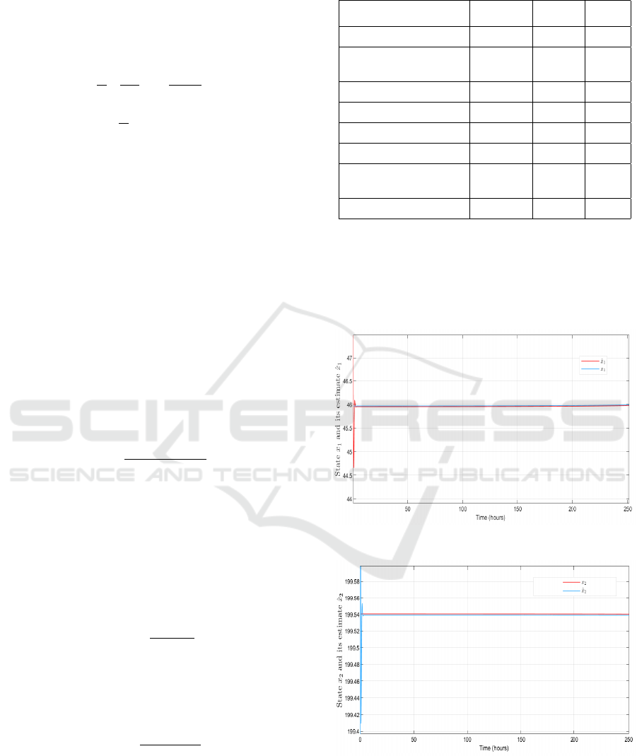
Figure 3: State x
1
and its estimate ˆx
1
.
Figure 4: State x
2
and its estimate ˆx
2
.
Figures 3, 4, 5, 6 and 7 show that the estimated
states ˆx
1
, ˆx
2
, ˆx
3
, ˆx
4
and the duty cycle
ˆ
d converge well
in finite time. Figure 8 and 9 also shows the estimates
of the IGBT’s RUL respectively according to the esti-
mations of R
ON
and the duty cycle. The RUL thresh-
ICINCO 2020 - 17th International Conference on Informatics in Control, Automation and Robotics
198
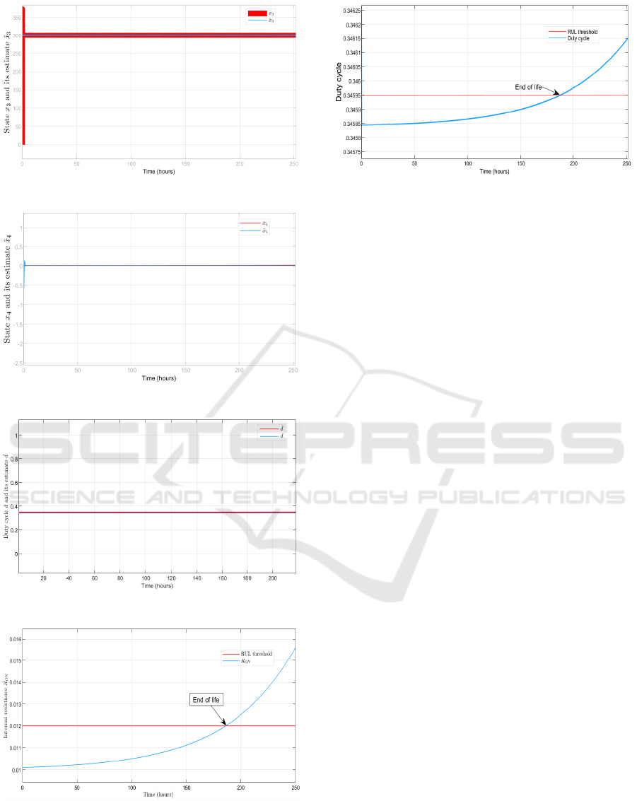
Figure 5: State x
3
and its estimate ˆx
3
.
Figure 6: State x
4
and its estimate ˆx
4
.
Figure 7: Duty cycle d and its estimate
ˆ
d.
Figure 8: RUL according to R
ON
.
old is set at 20% increase in the internal resistance
Ron of the IGBT, which corresponds to a variation of
0.4% increase in the duty cycle.
Figure 9: RUL according to duty cycle.
In this simulation case (ideal system), the end of
life of the IGBT is T = 185h. But in the real case the
end of life of the IGBT can be defined as follows:
T
End
= min
T
End
d
,T
End
Ron
(11)
where T
End
d
T
End
Ron
are respectively the end of life
calculated from the estimates of the duty cycle d and
the internal resistance R
ON
. The thresholds of vari-
ations are defined based on experiments. They can
vary depending on the authorized failure degree and
the operating time in failure mode (and therefore de-
pending on the application field).
5 CONCLUSION
In this paper, the online prognosis of RUL of IGBT
built into a DC-DC Boost converter has been pre-
sented. From the measurements of the input current
(I
IN
) and the output voltage (V
O
), we first obtained
an estimate of the current (x
1
) in the inductance and
the voltage (x
2
) in the output capacitor (voltage fil-
ter). Then these previous estimates allowed us to ob-
tain an estimate of the internal resistance of the IGBT
in its ON-state and the duty cycle of the control signal
of the IGBT. This ultimately served to predict the re-
maining useful life (RUL) of the IGBT operating on
a DC-DC converter. A simulation example has been
proposed to illustrate the results obtained. An appli-
cation on a real system (test bench) will be carried out
and the results obtained will be presented in our next
paper.
ACKNOWLEDGEMENTS
This work is co-funded by European Union and Nor-
mandy Region. Europe is involved in Normandy
through the European Funds for Regional Develop-
ment.
Real-time Prognosis of Failure of the IGBT in a Conversion Chain
199

REFERENCES
Al-Sheikh, H., Bennouna, O., Hoblos, G., and Moubayed,
N. (2014). Modeling, design and fault analysis of bidi-
rectional dc-dc converter for hybrid electric vehicles.
In 2014 IEEE 23rd International Symposium on In-
dustrial Electronics (ISIE), pages 1689–1695.
Alyakhni, A., Al-Mohamad, A., and Hoblos, G. (2019).
Estimation of mosfet degradation inside a dc dc con-
verter using joint kalman filtering. 4th International
Conference on Control and Fault-Tolerant Systems,
Sep 2019, casablanca, Morocco.
Bayerer, R., Herrmann, T., Licht, T., Lutz, J., and Feller,
M. (2008). Model for power cycling lifetime of igbt
modules - various factors influencing lifetime. In 5th
International Conference on Integrated Power Elec-
tronics Systems, pages 1–6.
Celaya, J., Saxena, A., Saha, S., and Goebel, K. (2011).
Prognostics of power mosfets under thermal stress
accelerated aging using data-driven and model-based
methodologies. Proceedings of International Confer-
ence on Prognostics and Health Management, Mon-
treal, 2.
Celaya, J. R., Saxena, A., Kulkarni, C. S., Saha, S., and
Goebel, K. (2012). Prognostics approach for power
mosfet under thermal-stress aging. In 2012 Proceed-
ings Annual Reliability and Maintainability Sympo-
sium, pages 1–6.
Dusmez, S., Heydarzadeh, M., Nourani, M., and Akin,
B. (2017). Remaining useful lifetime estimation for
power mosfets under thermal stress with ransac out-
lier removal. IEEE Transactions on Industrial Infor-
matics, 13(3):1271–1279.
Gillis, P. (1966). Manson-coffin fatigue. Acta Metallurgica,
14(12):1673 – 1676.
Kulkarni, C., Biswas, G., Celaya, J., and Goebel, K. (2011).
Prognostic techniques for capacitor degradation and
health monitoring.
Kulkarni, C., Celaya, J., Goebel, K., and Biswas, G. (2012).
Physics based electrolytic capacitor degradation mod-
els for prognostic studies under thermal overstress.
Lai, W., Zhao, Y., Chen, M., Wang, Y., Ding, X., Xu, S.,
and Pan, L. (2018). Condition monitoring in a power
module using on-state resistance and case tempera-
ture. IEEE Access, 6:67108–67117.
Langueh, K., Hoblos, G., and Chafouk, H. (2019). Online
estimation of the on-state resistance ron of a mosfet in
a conversion chain for failure prognostics. 15th Euro-
pean Conference on Advanced Control and Diagnosis,
Nov 2019, Bologna, Italy.
Levant, A. (1998). Robust exact differentiation via sliding
mode technique. Automatica, 34(3):379–384.
Levant, A. (2003). Higher-order sliding modes, differentia-
tion and output-feedback control. International Jour-
nal on automatic, 76(9/10):924–941.
Levant, A. (2005). Homogeneity approach to high-order
sliding mode design. Automatica, 41:823–830.
Levant, A. (2007). Finite differences in homogeneous dis-
continuous control. IEEE TAC, 52:1208–1217.
Levant, A. (2010). Chattering analysis. IEEE Transactions
on Automatic Control, 55(6):1380–1389.
Levant, A. and Livne, M. (2012). Exact differentiation of
signals with unbounded higher derivatives. IEEE TAC,
57(4):1076–1080.
Mohamed-Sathik, M., Prasanth, S., Sasongko, F., and Pou,
J. (2019). Online condition monitoring of igbt mod-
ules using current-change rate identification. Micro-
electronics Reliability, 92:55 – 62.
Reif, K., Sonnemann, F., and Unbehauen, R. (1999).
Nonlinear state observation using h/sub /spl infin//-
filtering riccati design. IEEE Transactions on Auto-
matic Control, 44(1):203–208.
Sathik, M., Jet, T. K., Gajanayake, C. J., Simanjorang,
R., and Gupta, A. K. (2015). Comparison of power
cycling and thermal cycling effects on the thermal
impedance degradation in igbt modules. In IECON
2015 - 41st Annual Conference of the IEEE Industrial
Electronics Society, pages 001170–001175.
Singleton, R. K., Strangas, E. G., and Aviyente, S. (2015).
Extended kalman filtering for remaining-useful-life
estimation of bearings. IEEE Transactions on Indus-
trial Electronics, 62(3):1781–1790.
Wang, H., Ma, K., and Blaabjerg, F. (2012). Design for reli-
ability of power electronic systems. In IECON 2012 -
38th Annual Conference on IEEE Industrial Electron-
ics Society, pages 33–44.
Yang, S., Xiang, D., Bryant, A., Mawby, P., Ran, L.,
and Tavner, P. (2010). Condition monitoring for
device reliability in power electronic converters: A
review. IEEE Transactions on Power Electronics,
25(11):2734–2752.
Zheng, Y., Wu, L., Li, X., and Yin, C. (2014). A relevance
vector machine-based approach for remaining useful
life prediction of power mosfets. In 2014 Prognostics
and System Health Management Conference (PHM-
2014 Hunan), pages 642–646.
ICINCO 2020 - 17th International Conference on Informatics in Control, Automation and Robotics
200
