
Design and Application of a Reconfigurable Control to a
Cyber-Physical System
Imane Tahiri
a
, Alexandre Parant
b
, François Gellot
c
, Alexandre Philippot
d
and Véronique Carré-Ménétrier
e
CReSTIC, University of Reims Champagne-Ardenne, Moulin de la Housse, Reims, France
Keywords: Discrete Event Systems, Fault Tolerant Control, Control Reconfiguration, Supervisory Control Theory,
Digital Twins, Cyber-Physical Systems.
Abstract: In the previous edition of ICINCO, authors have presented a theoretical comparison between centralized and
distributed control reconfiguration of Discrete Event Systems (DES). In this paper, we propose to enlarge the
proposition until the implementation step into a Programmable Logic Controller. The control is based on a
distributed architecture including time-delayed events and supervisory control theory. Moreover, in a context
of Industry 4.0, the verification and simulation phases are performed on a digital twin before implementation
on the real system.
1 INTRODUCTION
The continuous improvement of existing products,
the massive arrival of new ones on the market and
changes in environmental and safety legislation mean
that industries have to adapt in order to remain
competitive (Koren et al., 1999). In an Industry 4.0
context, modern manufacturing systems face an
aggressive international market composed of multiple
unpredictable changes; the paradigm of
Reconfigurable Manufacturing System has been
created to respond to these changes with limited cost.
(ElMaraghy, 2005; Koren et al., 1999).
Manufacturing systems are becoming more and
more complex with the arrival of Internet of Things
(IoT), the mass customization of products and the
increasing use of software in factories (W.
ElMaraghy et al., 2012). The increased complexity in
systems induces a large amount of information that
can lead the system to behave abnormally
(ElMaraghy et al., 2005).
Fault Tolerant Control (FTC) is intended to keep
the system available by mitigating unwanted behavior
a
https://orcid.org/0000-0003-2203-2604
b
https://orcid.org/0000-0001-8433-8671
c
https://orcid.org/0000-0001-8797-1704
d
https://orcid.org/0000-0001-5229-9452
e
https://orcid.org/0000-0002-9576-9108
that may occur when a failure happens. In case of
failure, the system must identify the resources
affected and substitute them with resources available
for reconfiguration; the system must then have
hardware and/or software redundancies (Dangoumau
et al., 2000).
Two types of FTCs are defined according to their
behaviour when a fault occurs: Passive Fault Tolerant
Control (PFTC) and Active Fault Tolerant Control
(AFTC) (Zhang & Jiang, 2008). PFTC are designed
to respond to a multitude of predefined failures, while
AFTC adapts the control to a failure actively. A
diagnostic block detects faults in the system and the
AFTC modifies the system controller to take the fault
into account. As a part of a AFTC process, (Tahiri et
al., 2019) presented an approach for reconfiguring the
control of a Cyber-Physical System (CPS).
CPS is one of the major technologies in the
evolution of industries towards the fourth industrial
revolution with IOT and cloud computing (Xu et al.,
2018). A CPS is composed of a set of virtual
computing elements interconnected and connected to
the physical world to link them together.
718
Tahiri, I., Parant, A., Gellot, F., Philippot, A. and Carré-Ménétrier, V.
Design and Application of a Reconfigurable Control to a Cyber-Physical System.
DOI: 10.5220/0009896107180725
In Proceedings of the 17th International Conference on Informatics in Control, Automation and Robotics (ICINCO 2020), pages 718-725
ISBN: 978-989-758-442-8
Copyright
c
2020 by SCITEPRESS – Science and Technology Publications, Lda. All rights reserved
In this work, CPSs were considered as discrete
event systems and are based on a comprehensive
methodology ranging from specification to
verification of the control implemented in a
controller.
This paper describes the implementation of this
approach on a flexible manufacturing system and on
its digital twin from University of Reims Champagne-
Ardenne experimental platform: Cellflex 4.0
(https://www.univ-reims.fr/meserp). Section 2 briefly
presents the methodology of (Tahiri et al., 2019). Its
implementation and the description of the platform
are introduced in Section 3. Section 4 takes the steps
of the benchmark approach practically before
concluding with a discussion.
2 PROPOSED APPROACH
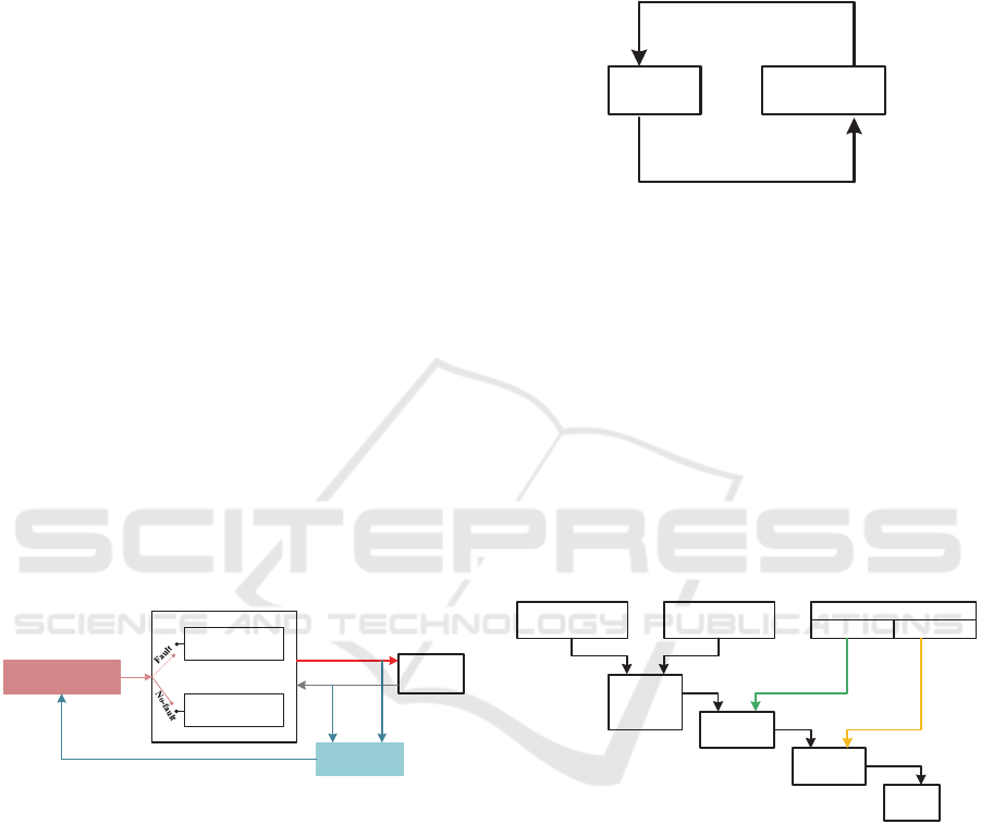
The approach used in this paper allows a system to be
reconfigured when a sensor failure occurs without
using redundant hardware. The system has a
diagnoser that detects failures and two different
controllers: one controlling the system in normal
behavior and the other taking action when a sensor
failure occurs (Figure 1). The second controller is
based on time estimation. Information lost due to
sensor malfunction are replaced by time-delayed
information to keep the system running.
Controller
(N)
Controller
(F)
Plant
Reconfiguration
Diagnoser
Control actions
Sensors signals
Sensors behaviors
Figure 1: Reconfiguration loop of the control.
2.1 Supervisory Control Theory
In this paper, we are interested in the problem of
reconfiguring the controller after a failure has
occurred in a specific class of system: Discrete Event
System (DES). The control law used is based on the
Supervisory Control Theory (SCT) introduced in
(Ramadge & Wonham, 1989). SCT allows supervisor
design that keeps the plant in a safe state of operation
according to the given control specifications.
SCT uses two separate automata (Figure 2). On
the one hand, a plant is modeled as an event generator.
On the other hand, the supervisor which receives as
input all events generated by the plant (controllable
and uncontrollable) and has the specifications
describing the desired behavior of the system. The
supervisor restricts the behavior of the system by
allowing or disallowing controllable events according
to the specifications.
Plant Supervisor
Con trol action s
Sensors signals
Figure 2: Control loop of the SCT.
The controller development is done in three steps
(Figure 3):
1. The operating part modelling of the system,
of the safety constraints (the forbidden
system behavior) and of the liveness
constraints (the authorized system
behavior);
2. The supervisor synthesis from the safety
constraints and from the operating part
model;
3. The synchronization of the supervisor with
the liveliness constraints to obtain the
controller.
S: Supervisor synthesis
| |: Synchronous composition
Actuators model
Detectors model
Specifications
Safety Liveliness
Plant
behavior
model (P)
Supervisor
(SUP)
Controller
(CONT)
PLC
| |
| |
S
Implementation
Figure 3: Controller overview steps.
2.2 Distributed Controller
Most of the approaches used for the controller
calculation are based on a centralized architecture.
The risk of these approaches is combinatorial
explosion due to the complexity of the systems. The
modelling of the operational part, of the safety and of
the liveliness constraints become laborious. To
overcome this problem, the method implemented in
this paper uses a distributed approach based on the
work of (Qamsane et al., 2017) :
1. The plant is decomposed into several plant
elements PE (n x PE);
Design and Application of a Reconfigurable Control to a Cyber-Physical System
719
2. The local safety and liveliness specifications
are modelled for each PE as well as global
specifications for the plant;
3. The local controllers for each PE are
synthesized using the local safety and
liveliness specifications;
4. The global safety and liveliness
specifications are used to synthesize the
distributed controller of each PE;
5. The distributed controllers are interpreted in
Grafcet (IEC60848 standard);
6. All the obtained grafcets are implemented in
an industrial Programmable Logic
Controller (PLC) thanks to programming
languages (IEC61131-5 standard).
The method used in (Tahiri et al., 2019b)
introduces three additional steps allowing:
- The synthesis of two controllers for each PE:
one for normal behavior and one considering
the occurrence of a fault;
- The synthesis of reconfiguration rules in
addition to the global specifications;
- The interpretation of the reconfiguration
rules in Grafcet to define the switching
between the grafcets of the two controllers
of each PE.
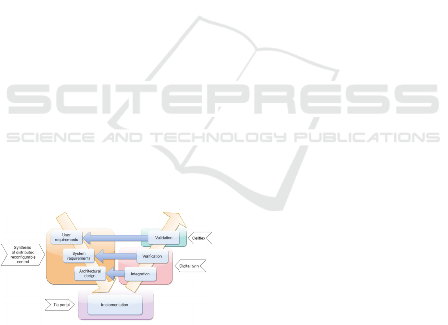
3 IMPLEMENTATIONS ON A CPS
The specification, verification and validation of the
control follow V-cycle structure (validation and
verification model), which allows a return to the
design stages if the tests performed are inconclusive
(Figure 4).
Figure 4: Control design cycle.
The design phases are performed using the
approach presented in the previous section. The
contribution of this paper is the use of a digital twin
to simulate and verificate the reconfigurable control
before its validation on real manufacturing system.
The engineer who designs the control can forget
constraints or make programming errors during
implementation. Feedback loop in the control design
cycle allows adjustments of local and global
constraints or corrections in the PLC program.
3.1 Using Digital Twins for
Development in Industry 4.0
Industry 4.0 has become a priority in research and
industry in recent years. The aims of Industry 4.0 are
to reduce development time, customize the product
on-demand, improve decision making and resources
management (Lasi et al., 2014).
All of the plant components are integrated and
connected to a central computer, the cyber-physical
system (CPS), that coordinates the whole (Rodič
Blaž, 2017). CPS forms a network of digital elements
interacting with physical inputs and outputs. CPS and
digital twin aim to bridge the physical and digital
worlds. The difference lies in the approach used: the
central components of CPS are sensors and actuators
whereas digital twins are centered on a model-
oriented approach. The digital twin can be integrated
into the CPS to improve simulation modelling (Rodič
Blaž, 2017) or to improve its management in real-
time (Tao et al., 2019).
A digital twin is a virtual representation of a real
system. It contains different models that are
interconnected to reproduce the behavior of the real
system: the physical model, the functionality model
and the communications interfaces (Schluse &
Rossmann, 2016).
Digital twins will make it possible in the coming
years to integrate simulation as an integral phase of
the life cycle and one of the main system
functionalities (Rosen et al., 2015). Their use for
development, verification and validation will reduce
development costs and enable the design of safer and
more robust systems (Schluse & Rossmann, 2016).
Digital twins can be divided into 3 sub-categories
depending on the type of exchange between the real
physical system and the digital one: the digital model,
the digital shadow and the digital twin (Kritzinger et
al., 2018). The digital twin used in this paper is
classified in the sub-category “digital model”, it
digitally represents the real system but there is no
automatic data exchange between the two systems. A
change of state in one of the systems must be
manually transferred to the other system. This level
of integration is still enough to carry out the
verification and simulation phases of the
reconfigurable control.
ICINCO 2020 - 17th International Conference on Informatics in Control, Automation and Robotics
720
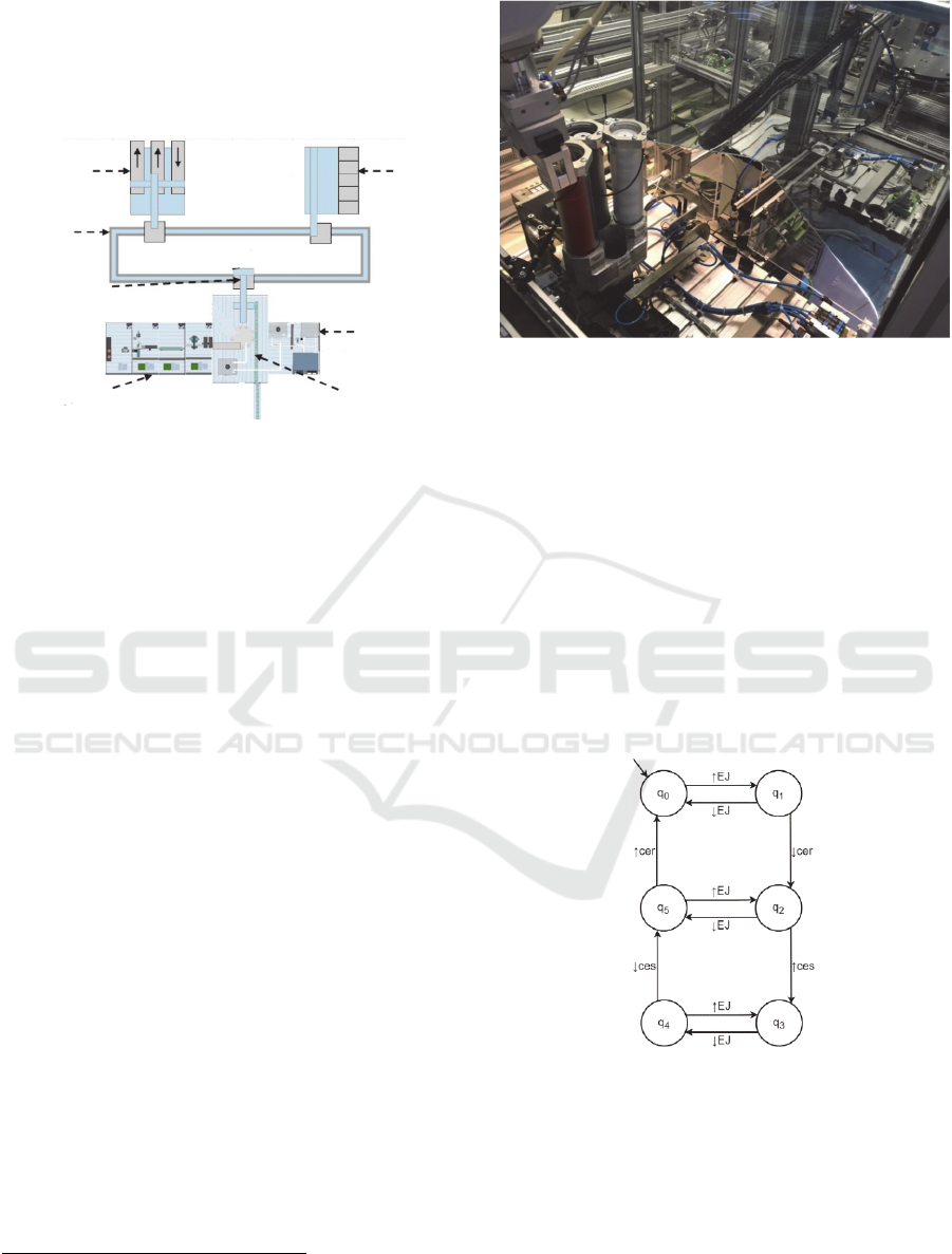
3.2 Description of the CPS
The implementation of the reconfigurable control is
carried out on the flexible manufacturing system
Cellflex 4.0.
Storage
station
Process
station
Filling and
screwing station
Cap supply
station
Transfer
station
Conveyor
Import/Export
station
Figure 5: Workstation of the Cellflex 4.0.
The aim of the system is to fill bottles to group
them in batches of six in sixpacks and finally store
them. First, the import-export station brings the
sixpacks onto the central conveyor that connects each
workstation. Each sixpack is placed on a wagon. At
the same time, caps are fed to the filling station by the
cap supply station while the bottles are being filled.
The bottles are closed in the filling station and
transported to the transfer station. When six bottles
are available, a sixpack is fed to the transfer station
and the bottles are placed three by three on it. Then,
the sixpacks returned to the import-export station for
export from the system. If the station is full, the
sixpacks are temporarily stored in the storage station
(Figure 5).
4 SYNTHESIS OF THE
RECONFIGURABLE
CONTROL
In this paper, we implement the control on the
Cellflex 4.0 cap supply station (Figure 6).
This station consists of eight actuators controlled
by various technologies and fifteen sensors. The PE
defined for the station are the cap dispenser, the
ejector cylinder, the rotary cylinder, the suction cup
of the rotary cylinder, the conveyor, the handling arm,
the gripper of the handling arm and the conveyor of
the handling arm.
1
https://www.univ-reims.fr/meserp/projets/factories-of-
future-champagne-ardenne-f.f.c.a/cper-f.f.c.a,24346,
40021.html
Figure 6: Cellflex 4.0 cap supply station.
4.1 Example of a Distributed
Controller Synthesis
We have synthesized the distributed controllers for
each PE defined previously. We will only detail the
distributed controller design of the ejector cylinder in
this article, but the design steps of each PE can be
found at the following links
1
.
4.1.1 Synthesis of the Local Controller
The first step in the synthesis of the distributed
controller is the modelling of the PE model of normal
and timed mode.
Figure 7: The ejector cylinder model of normal mode.
The ejector cylinder model of normal mode is
obtained by synchronizing the actuator model and the
sensor model (Figure 7). The ejector cylinder is
monostable; thus, it has only one actuator activated
by the action EJ and two sensors indicating if the
Design and Application of a Reconfigurable Control to a Cyber-Physical System
721
cylinder is retracted cer or if the cylinder is extended
ces. The ejector cylinder model take into account the
mutual exclusivity of ces and cer. They can’t be
active at the same time, the occurrence of this event
is the consequence of a fault (sensor stuck-on for
example).
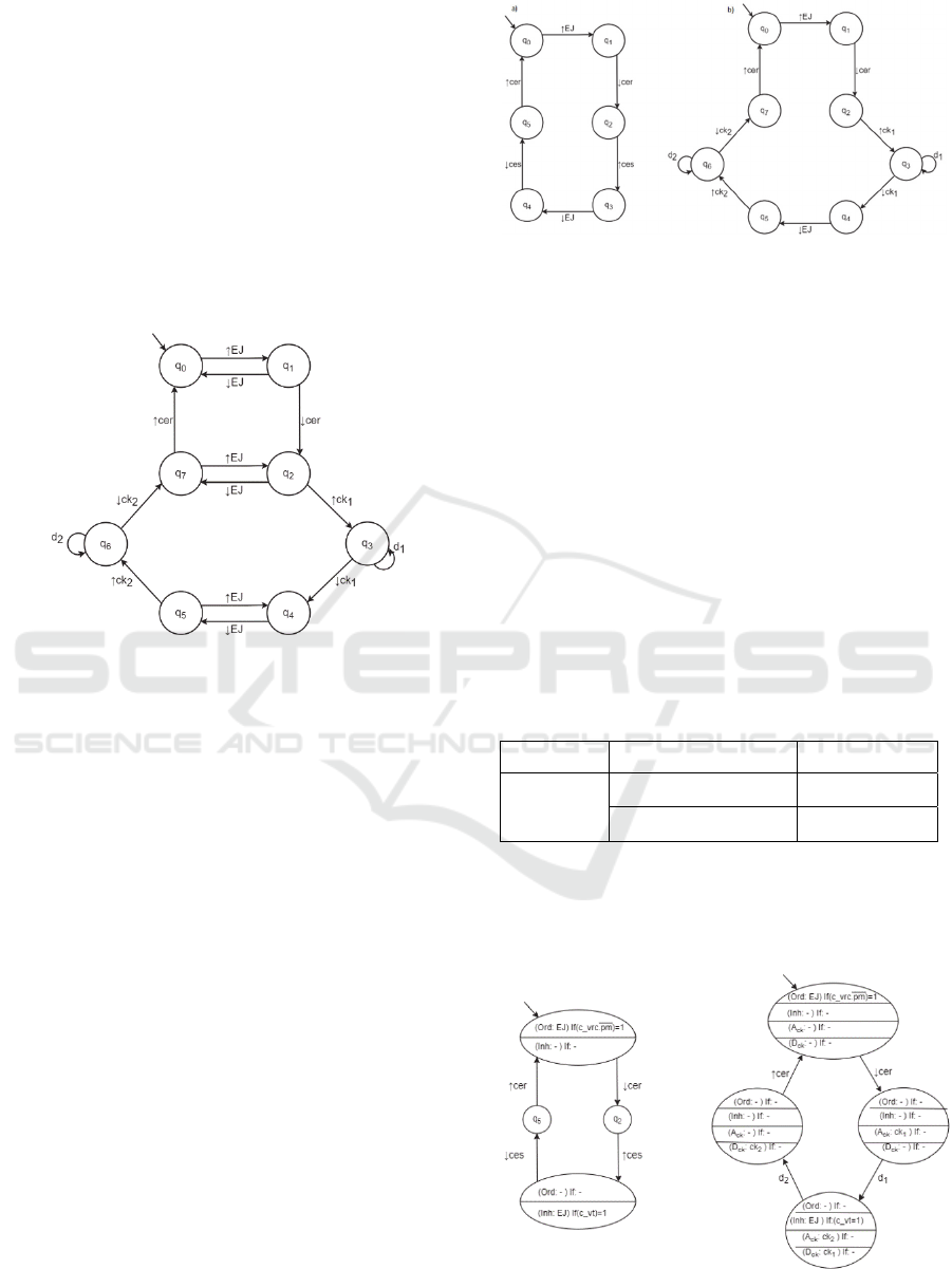
In this example, we consider that the sensor ces is
faulty and the information sent is no longer reliable.
The activation time d
1
and deactivation time d
2
of the
sensor have been estimated and measured by clock
ck
1
and ck
2
. The ejector cylinder model of timed
mode is obtained by replacing ces information by the
timed information (Figure 8).
Figure 8: The ejector cylinder model of timed mode.
The normal behavior of this element corresponds
to the output of the cylinder with the action EJ until
the sensor ces is activated; then this action must be
inhibited to retract the cylinder until the sensor cer is
activated. To prevent transitions in the model that
deviate from this behavior, the liveliness constraints
have been defined in normal mode by:
(q
1
+ q
2
) . ↓ EJ = 0 (1)
(q
4
+ q
5
) . ↑ EJ = 0 (2)
The liveliness constraints of the timed mode are
defined by:
(q
1
+ q
2
) . ↓ EJ = 0 (3)
(q
5
+ q
7
) . ↑ EJ = 0 (4)
These liveliness constraints reflect the functional
safety of the ejector cylinder: activation and
deactivation commands must be active until the
corresponding sensor is activated.
The synchronization of previous models with the
corresponding local specification equations gives the
local controllers LC
N
corresponding to the normal
behavior and LC
F
corresponding to the timed
behavior.
Figure 9: a) LC
N
, b) LC
F
of the ejector cylinder.
4.1.2 Synthesis of the Distributed Controller
The ejector cylinder has physical interfaces with the
cap dispenser and the rotary cylinder on which the
suction cup is located. The caps are ejected from the
magazine and feed the rotary cylinder.
The ejector cylinder output is conditioned by the
presence of a cap in the magazine: the sensor pm
indicating this presence is used, it is active at 0. The
rotary cylinder must be on the conveyor side (sensor
c_vrc) so that it does not block the ejector output. The
cylinder’s retraction is conditioned by the cap being
grasped by the suction cup: the sensor c_vt of the
suction cup indicating the under-pressure section cup
is used. These global liveliness constraints are
grouped in the form of equation in table 1.
Table 1: Global liveliness constraints.
PE Condition if Then
Ejector
cylinder
𝑐
_
𝑣𝑟𝑐. 𝑝𝑚
1
Ord EJ
𝑐
_
𝑣𝑡 1
Inh EJ
The synchronization of global liveliness
constraints with LC
N
and LC
F
gives the distributed
controllers DC
N
and DC
F
corresponding to normal
and to faulty behavior (Figure 10).
Figure 10: a) DC
N
, b) DC
F
of the ejector cylinder.
ICINCO 2020 - 17th International Conference on Informatics in Control, Automation and Robotics
722
The distributed controller of each mode is then
interpreted in Grafcet (Figure 11) following the
approach described in (Qamsane et al., 2017).
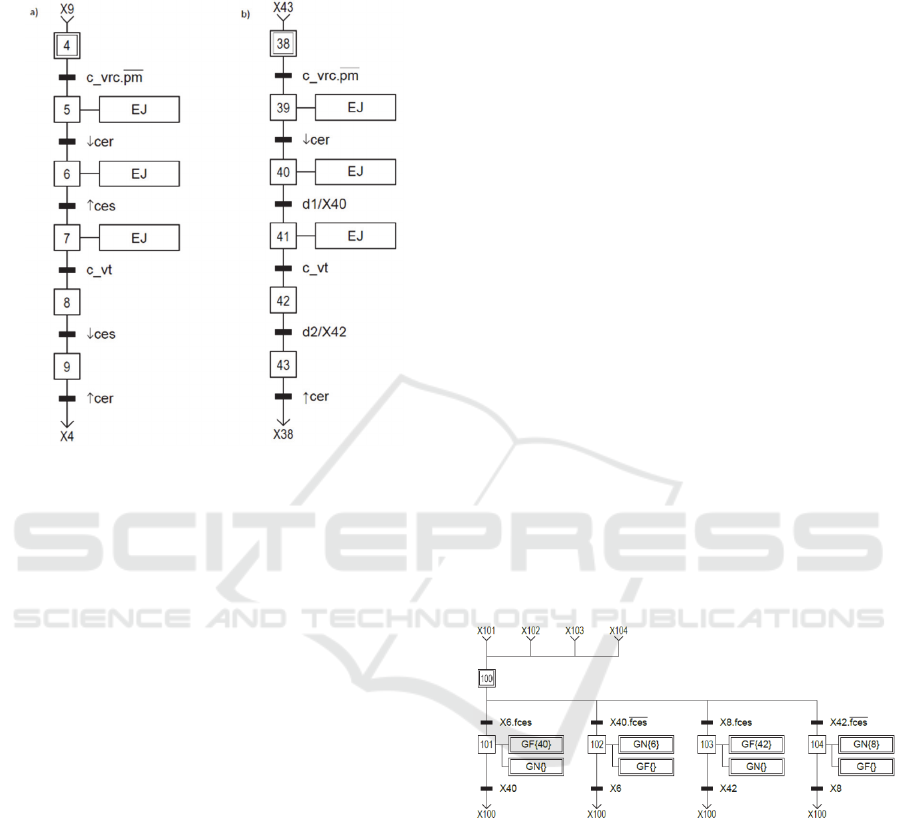
Figure 11: a) Grafcet interpretation of DC
N
, b) Grafcet
interpretation of DC
F
of the ejector cylinder.
The differences between the two grafcets are
minimal, there are only two transitions that are
modified. It is the information from the faulty sensor
that is replaced by time delays. Nevertheless, the
interest of this approach lies in the global construction
methodology which is generalizable to any type of
DES. The two grafcets allow the operator to
distinguish in which mode the system is in to detect a
sensor failure.
4.1.3 Synthesis of the Reconfiguration Rules
Last step is to synthesize the reconfiguration grafcets
from the reconfiguration rules.
The reconfiguration rules allow to switch from
normal mode to timed mode when a failure occurs or
to switch from timed mode to normal mode when the
failure is corrected.
The reconfiguration rules are defined by logical
equations such as:
RC : If X
i
and f
s
= 1 Then
(F: G
F
{X
ji
}) and (F: G
N
{})
Else If X
ji
and f
s
= 0 Then
(F: G
N
{X
i
}) and (F: G
F
{})
(5)
With:
- F: forcing operation
- G
N
: grafcet interpretation of DC
N
- G
F
: grafcet interpretation of DC
F
-
X
i
: Boolean variable associated with step “i”
of G
N
and X
ij,
corresponding variable
associated with step “ji” of G
F
.
-
f
s
: Boolean variable indicating the
occurrence of a failure on the sensor (f
s
=1).
Equation 5 defines transition from G
N
to G
F
: when
step X
i
of G
N
is active and the failure has occurred.
Then, step X
ji
of G
F
is forced and G
N
is deactivated. It
also defines the reverse switch: when X
ij
of G
F
is
active, and the failure has been repaired. Then, step
X
i
of G
N
is forced and G
F
is deactivated.
The sensor ces failure is associated with the
variable f
ces
. We have defined two reconfiguration
rules: one allowing the passage from one grafcet to
the other before ces activation and the other passage
before its deactivation. These rules are defined by:
RC
1
: If X
6
and f
ces
= 1 Then
(F: G
F
{X
40
}) and (F: G
N
{})
Else If X
40
and f
ces
= 0 Then
(F: G
N
{X
6
}) and (F: G
F
{})
(6)
RC
2
: If X
8
and f
ces
= 1 Then
(F: G
F
{X
42
}) and (F: G
N
{})
Else If X
42
and f
ces
= 0 Then
(F: G
N
{X
8
}) and (F: G
F
{})
(7)
Reconfiguration rules are interpreted in Grafcet to
obtain the reconfiguration grafcet (Figure 12).
Figure 12: Reconfiguration grafcet.
The grafcets of each PE and the reconfiguration
grafcet are translated into Ladder Diagram (LD)
language to be implemented in a PLC. We used Tia
Portal (Total Integrated Automation Portal) software
developed by Siemens to write the PLC program.
Grafcet is commonly used and well know in
industry but it is a specification tool. We illustrate our
example by ladder language but it is at the discretion
of the end user to chose the language. Other technique
using Petri net can be used. However, to our
appreciation, PN is more academic than industrial in
its use.
Design and Application of a Reconfigurable Control to a Cyber-Physical System
723

4.2 Verification and Simulation
Program verification tests is defined in two steps:
1. Verification of deadlock and liveness
properties of the code before implementation
by Model-Checking.
2. Simulation on the digital twin of the Cellflex
4.0 (Figure 13).
The contribution consists of designing two
modes: normal behavior and one tacking into account
the fault detection. The switch between them is
ensured by the set of reconfiguration rules presented
by several Grafcets. The reconfiguration Grafcets are
strongly solicitate. It is, therefore, necessary to ensure
the non-blocking of all the implanted control
Grafcets. For this, the distributed controllers are
verified through a model-checker before the
implementation in a PLC. This contribution is not
presented into the paper.
The second step is the use of the proposition in a
context of Industry 4.0. The digital twin is designed
with the Siemens NX MCD (NX Mechatronics
Concept Designer) software. The digitally designed
elements of the Cellflex are imported into NX MCD
and then, the physical interactions are defined to
replicate the behavior of the real system. The digital
twin also has the same control and command
interfaces as the Cellflex.
The program is integrated into a simulated PLC
using PLCSIM Advanced software developed by
Siemens, it allows the link to be made with the digital
twin by simulating TCP/IP communication. The input
and the output mnemonics of the digital twin and the
Figure 13: Digital twin cap supply station.
2
https://www.univ-reims.fr/meserp/projets/factories-of-
future-champagne-ardenne-f.f.c.a/cper-f.f.c.a,24346,
40021.html
simulated PLC must match to synchronize the PLC
program with the sensors and actuators of the digital
twin.
Several simulations have been performed on the
digital twin, without failure in the first instance, to
estimate the times required for the activation and
deactivation of the sensor ces.
Then, we simulated the sensor failure and
checked the system behavior with the grafcet of timed
mode. A video comparing the system behavior with
and without the failure can be find at the following
link
2
.
The system retains similar behavior and
performance despite the failure thanks to the
implementation of the reconfigurable control and
precise time estimation timed mode. The
reconfiguration grafcet allow instantaneous control
changeover without latency in the system.
5 CONCLUSIONS
We have presenting and implementing a
reconfigurable fault-tolerant control on a flexible
manufacturing system and its digital twin in this
paper.
The proposed approach uses SCT and distributed
controller synthesis to reconfigure the controller
when a failure occurs on a sensor. The control was
designed using finite state machine and interpreted
using Grafcet. The implementation has been carried
out on a simulated PLC connected to the digital twin
to check the behavior and performance of the system.
This approach can be done iteratively. In this paper,
only one failure is considered but failures of other
sensors can be easily added. When the DC
N
of each
PE are validated, it is then sufficient to repeat the
methodology of section 4 by adding only the sensor
specific timed information. The sensor information
must be replaced by a timed information and interpret
the distributed controller in grafcet. The appropriate
reconfiguration rules must be added to the
reconfiguration grafcet. The grafcets are verified by
model-checking and implemented in the PLC to
perform the simulation phases.
The digital twin used to implement the approach
was designed after the actual manufacturing system.
In this situation, the design and development of a
digital twin is an expensive and tedious phase to
obtain a reliable twin that reproduces the behavior of
ICINCO 2020 - 17th International Conference on Informatics in Control, Automation and Robotics
724

the real system as closely as possible. The digital twin
must also be kept up to date with every change in the
real system, including a new design and development
phase.
Despite these drawbacks, the use of the digital
twin reduces the cost and time of the simulation
phases while preserving the real system. Errors can
occur during the design of the reconfigurable control.
For instance, some safety or liveliness constraints
may be forgotten or may not be enough for the correct
operation of the system. Errors can also occur during
the implementation of the control in the PLC. As the
digital twin is contained in software, it cannot be
physically damaged. However, it still exposed to
software issues. Embedded software has restriction
has well and it needs high computing power to run
accurately.
ACKNOWLEDGEMENTS
This work is integrated in the project FFCA
(Factories of Futur Champagne-Ardenne). The
authors would like to thank the region Grand-Est
within the project FFCA (CPER PFEXCEL).
REFERENCES
Dangoumau, N., Toguyeni, A. K. A., Dupas, M., & Craye,
E. (2000). Reconfiguration Processes for Automated
Production Systems. 2nd IFAC Conference on
Management and Control of Production and Logistics
(MCPL 2000), Grenoble, France, 5-8 July 2000,
33(17), 843–848. https://doi.org/10.1016/S1474-
6670(17)39513-7
ElMaraghy, H.A., Kuzgunkaya, O., & Urbanic, R. J.
(2005). Manufacturing Systems Configuration
Complexity. CIRP Annals, 54(1), 445–450.
https://doi.org/10.1016/S0007-8506(07)60141-3
ElMaraghy, Hoda A. (2005). Flexible and reconfigurable
manufacturing systems paradigms. International
Journal of Flexible Manufacturing Systems, 17(4),
261–276. https://doi.org/10.1007/s10696-006-9028-7
ElMaraghy, W., ElMaraghy, H., Tomiyama, T., &
Monostori, L. (2012). Complexity in engineering
design and manufacturing. CIRP Annals, 61(2), 793–
814. https://doi.org/10.1016/j.cirp.2012.05.001
Koren, Y., Heisel, U., Jovane, F., Moriwaki, T., Pritschow,
G., Ulsoy, G., & Van Brussel, H. (1999).
Reconfigurable Manufacturing Systems. CIRP Annals,
48(2), 527–540.
Kritzinger, W., Karner, M., Traar, G., Henjes, J., & Sihn,
W. (2018). Digital Twin in manufacturing: A
categorical literature review and classification. 16th
IFAC Symposium on Information Control Problems in
Manufacturing INCOM 2018, 51(11), 1016–1022.
https://doi.org/10.1016/j.ifacol.2018.08.474
Lasi, H., Fettke, P., Kemper, H.-G., Feld, T., & Hoffmann,
M. (2014). Industry 4.0. Business & Information
Systems Engineering, 6(4), 239–242. https://doi.org/
10.1007/s12599-014-0334-4
Qamsane, Y., Tajer, A., & Philippot, A. (2017). A synthesis
approach to distributed supervisory control design for
manufacturing systems with Grafcet implementation.
International Journal of Production Research, 55(15),
4283–4303.
https://doi.org/10.1080/00207543.2016.1235804
Ramadge, P. J. G., & Wonham, W. M. (1989). The control
of discrete event systems. Proceedings of the IEEE,
77(1), 81–98. https://doi.org/10.1109/5.21072
Rodič Blaž. (2017). Industry 4.0 and the New Simulation
Modelling Paradigm. Organizacija, 50(3), 193.
https://doi.org/10.1515/orga-2017-0017
Rosen, R., von Wichert, G., Lo, G., & Bettenhausen, K. D.
(2015). About The Importance of Autonomy and
Digital Twins for the Future of Manufacturing. 15th
IFAC Symposium OnInformation Control Problems
InManufacturing, 48(3), 567–572. https://doi.org/
10.1016/j.ifacol.2015.06.141
Schluse, M., & Rossmann, J. (2016). From simulation to
experimentable digital twins: Simulation-based
development and operation of complex technical
systems. 2016 IEEE International Symposium on
Systems Engineering (ISSE)
, 1–6. https://doi.org/
10.1109/SysEng.2016.7753162
Tahiri, I., Philippot, A., Carre-Menetrier, V., & Tajer, A.
(2019). Time-Based Estimator for Control
Reconfiguration of Discrete Event Systems (DES).
2019 6th International Conference on Control,
Decision and Information Technologies (CoDIT),
1084–1089.
https://doi.org/10.1109/CoDIT.2019.8820585
Tao, F., Qi, Q., Wang, L., & Nee, A. Y. C. (2019). Digital
Twins and Cyber–Physical Systems toward Smart
Manufacturing and Industry 4.0: Correlation and
Comparison. Engineering, 5(4), 653–661.
https://doi.org/10.1016/j.eng.2019.01.014
Xu, L. D., Xu, E. L., & Li, L. (2018). Industry 4.0: State of
the art and future trends. International Journal of
Production Research, 56(8), 2941–2962.
https://doi.org/10.1080/00207543.2018.1444806
Zhang, Y., & Jiang, J. (2008). Bibliographical review on
reconfigurable fault-tolerant control systems. Annual
Reviews in Control, 32(2), 229–252. https://doi.org/
10.1016/j.arcontrol.2008.03.008
Design and Application of a Reconfigurable Control to a Cyber-Physical System
725
