
Formalization and Verification of Reconfigurable Discrete-event System
using Model Driven Engineering and Isabelle/HOL
Sohaib Soualah
1,4 a
, Yousra Hafidi
1,2,4 b
, Mohamed Khalgui
1 c
, Allaoua Chaoui
3 d
and Laid Kahloul
2
1
LISI Laboratory, National Institute of Applied Sciences and Technology, University of Carthage, Tunis 1080, Tunisia
2
LINFI Laboratory, Computer Science Department, Biskra University, Algeria
3
MISC Laboratory, Faculty of NTIC, University Constantine 2 - Abdelhamid Mehri, Constantine, Algeria
4
University of Tunis El Manar, Tunis, Tunisia
Keywords:
Reconfigurable Discrete-event Systems, Model Driven Engineering, Model Transformation, Meta-model
Formal Verification, Theorem Prover, Isabelle/HOL.
Abstract:
This paper deals with the modelling and verification of reconfigurable discrete event systems using model
driven engineering (MDE) and Isabelle/HOL. MDE is a software development methodology followed by
engineers. Isabelle/HOL is an interactive/automated theorem prover that combines the functional program-
ming paradigm with high order logic (HOL), which makes it efficient for developing solid formalizations.
We are interested in combining these two complementary technologies by mapping elements of MDE into
Isabelle/HOL. In this paper, we present a transformation process from Ecore models, to functional data struc-
tures, used in proof assistants. This transformation method is based on Model-driven engineering and defined
by a set of transformation rules that are described using formal presentations. Furthermore, in order to avoid
redundant computations in RDESs, we propose a new algorithm for improved verification. We implement the
contributions of this paper using Eclipse environment and Isabelle tool. Finally, we illustrate the proposed
approach through FESTO MPS case study.
1 INTRODUCTION
The development of safe systems in industry is con-
sidered as an important task because a failure can be
critical according to a domain for example: air and
railway traffic control (Khalgui et al., 2012), manu-
facturing systems (Khalgui et al., 2010), real time sys-
tems and intelligent control systems (Khalgui et al.,
2010). In this context, the main objective of a sys-
tem is to answer the compromise flexibility vs per-
formance (Hafidi et al., 2019), which means that new
developed systems guarantee performance by giving
response to customer’s needs. Many existing works
have been proposed in this perspective of flexibility,
which give as result new types of systems. A class
of these systems is that of reconfigurable discrete-
event systems (RDESs) which are characterized by
a
https://orcid.org/0000-0002-5162-5989
b
https://orcid.org/0000-0002-3543-6731
c
https://orcid.org/0000-0001-6311-3588
d
https://orcid.org/0000-0003-3751-8084
their discrete nature and their changeable structures.
RDESs are affected by their internal as well as ex-
ternal events. An RDES is defined as a hardware
or software automation system capable of modifying
its internal structure to adapt its answers to its envi-
ronment changes (Khalgui et al., 2019). We distin-
guish between two kinds of reconfigurations: static
and dynamic (Zhang et al., 2017). The former is
applied offline before running the system. The lat-
ter is applied automatically at run-time without any
interruption. Dynamic reconfigurations can be exe-
cuted: (1) manually by users, (2) automatically by
agents (robot, machine, schedule, etc.), and (3) in a
hybrid way which is the combination of manual and
automatic reconfigurations. To deal with the safety
of reconfigurable discrete event systems, researchers
are following many verification approaches. Model
checking (Clarke et al., 2018) is one of the most used
solutions to validate systems. It presents an automatic
verification technique to check functional properties.
Model-checking uses mathematical methods to ver-
250
Soualah, S., Hafidi, Y., Khalgui, M., Chaoui, A. and Kahloul, L.
Formalization and Verification of Reconfigurable Discrete-event System using Model Driven Engineering and Isabelle/HOL.
DOI: 10.5220/0009893602500259
In Proceedings of the 15th International Conference on Software Technologies (ICSOFT 2020), pages 250-259
ISBN: 978-989-758-443-5
Copyright
c
2020 by SCITEPRESS – Science and Technology Publications, Lda. All rights reserved

ify if a property is satisfied in a given system model.
If the property is violated, a counter example of the
system execution is provided. Authors in (Guellouz
et al., 2016) propose an extension to the IEC 61499
(Lewis, 2001) standard called Reconfigurable Func-
tion Block, encapsulating several reconfiguration sce-
narios in one function block. In order to verify the
system and to evaluate its performance, authors model
it using a class of Petri nets called GR-TNCES (Khlifi
et al., 2015). After that, PRISM is used as a model
checker to verify the safety of each reconfiguration
scenario of the system. In (Zhang et al., 2013), au-
thors propose a new extension of TNCES formalism
named reconfigurable net condition/event systems (R-
TNCESs). This last allows to deal with reconfigura-
tion and time properties with modular specification in
the same formalism. In (Hafidi et al., 2018), a new
methodology for formal verification of reconfigurable
discrete event control systems (RDECSs) is proposed
in order to ensure the correctness of systems. The
proposed contribution includes an improved model-
ing and verification of RDECSs. The main idea is
based on the checking of reconfiguration scenarios
(inter-verification) and also the checking of the inter-
nal behavior of each configuration (intra-verification).
All these research works present significant results
regarding the verification task of RDESs. However,
there has been a luck of researches about the opti-
mization of the verification task considering analysed
properties. Actually, the complexity of model check-
ing depends on two parameters: the size of the model,
and the number of properties to be verified. For in-
stance, Bounded Model Checking (BMC) is based on
a reduction of model checking to satisfiability formu-
lae (Jiang et al., 2016). We propose, in this work a
new methodology for the formalization and verifica-
tion of RDESs using theorem proving Isabelle/HOL
to overcome model checking limits. Using such a the-
orem proving has several advantages. First, it gives
a certificate to formal proof when it succeeds. Sec-
ond, when the verification of the given property fails,
it generates a counterexample as a proof to the for-
mula negation, instead of a sequence of states or trees
labeled with states, as in traditional model checkers.
To the author’s best knowledge, this is the first contri-
bution addressing this problem. This paper presents
the following contributions:
• We define a Meta-Model to model RDESs using
MDE. Which is part of the evolution by advocat-
ing the systematic use of models to facilitate un-
derstanding of a complex system and to automate
some of the development processes followed by
engineers.
• We propose a formalisation of RDESs in Isabelle,
which is equivalent to this Meta-model.
• We establish the link between MDE and Isabelle
by defining reconfiguration rules to allow auto-
matic generation of system in Isabelle.
• In order to avoid redundant computations, we pro-
pose a new algorithm for improved verification.
The remainder of this paper is organized as follows,
Section II presents background about Model Driven
Engineering (MDE), and Isabelle/HOL. Sections III
and IV involve details about the proposed approach.
Section V presents the new Algorithm of improved
verification. Section VI describes an application of
proposed contributions on a real case study: FESTO
benchmark system. Section VII illustrates perfor-
mance evaluation of the suggested approach. Finally,
Section VIII concludes this paper and highlights some
perspectives of the work.
2 BACKGROUND
In this section, we present details about Isabelle/HOL
theorem proving, and Model Driven Engineering.
2.1 Isabelle/HOL
Isabelle/HOL is an interactive/automated theorem
prover that combines the functional programming
paradigm with high order logic (HOL), which
makes it efficient for developing solid formalizations
(Meghzili et al., 2017). Using Isabelle/HOL, we can
formalize a system and prove its properties (i.e., for-
malize systems, formulating lemmas and theorems on
them) (Ali et al., 2007). Isabelle/HOL has a high de-
gree of credibility for created proofs because it allows
us to prove every step, and therefore the whole proof
is correct. Isabelle has several methods, to describe
data structures. In the following, we show the main
Isabelle concepts used in this paper.
• The theory: The main concept enveloping all ele-
ments used to write a program in Isabelle/HOL.
• Types bool, nat and list: These are the most im-
portant predefined types. Although the lists are
already predefined, and can define their own type.
• Types synonym: Synonym types are abbrevia-
tions for existing types.
• Function: In most cases, defining a recursive
function is as simple as other definitions.
• Record: A record in Isabelle is an element en-
veloping more than one type, to define another
type.
• Lemma: is used to prove a function or properties.
Formalization and Verification of Reconfigurable Discrete-event System using Model Driven Engineering and Isabelle/HOL
251
2.2 Model Driven Engineering
Model Driven Engineering (MDE) is a software
development methodology followed by engineers,
where meta-models are the central elements. A meta-
model precisely defines concepts handled in the mod-
els as well as the relationships between these con-
cepts. A model is a description, a specification of a
system. A model transformation describes the switch
from a source model to a target one. MDE is a gen-
eral and open approach following the proposal of the
MDA (Model Driven Architecture) standard proposed
by the OMG in 2000 (Djeddai et al., 2012). We ap-
ply this method to describe, specify systems, then to
define a generic transformation processe from Ecore
models (As detailed in the next subsection) to Is-
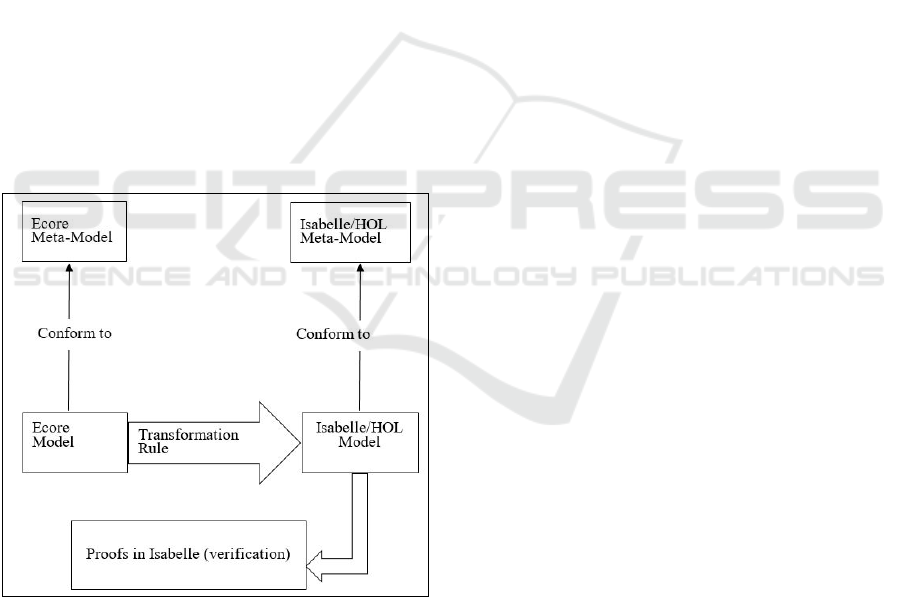
abelle/HOL. Figure 1 shows an overview of our trans-
formation. For the translation, we propose Ecore
meta-model of the system. This meta-model is the
constructor of source model of our transformation.
We also define Isabelle/HOL meta-model to be the
constructor of target model. To perform this transfor-
mation, we define a set of transformation rules (de-
tailed in Section. 4) that maps components of the in-
stance of Ecore meta-model to those instances of Is-
abelle/HOL meta-models.
Figure 1: An overview of our transformation.
• Ecore Meta-model
In this paper we use a subset of the Ecore meta-
model. This subset essentially contains the elements
we needed for translation from Ecore model to Is-
abelle/HOL. It is important to note that this subset of
Ecore allows us to define basic models validated by
Ecore. A subset of the Ecore meta-model consists of:
• The EPackage gathers all Eclasses and Edatatypes
via EClassifers. It is the root element of the Ecore
models.
• The EClass is the element that represents the
UML class in Ecore. Eclasses define the structure
of the objects that make up the instances of the
model. It contains EAttributes and EOperations.
• EReferences represent an entire/partial relation-
ship called
value aggregation
in UML.
3 METHODOLOGY
In this section, we propose the “Meta-Model” to
model RDES before transforming it in Isabelle/HOL.
A “Meta-Model” consists of the elements and rela-
tions used to describe: (1) behavior of system which
is all system configurations, and (2) Reconfigura-
tions rules allowing automatic transformations be-
tween configurations.
3.1 ECORE Meta-model
Definition 1: An RDES is composed of n Units
as follows: RDES = Unit1, Unit2, ...,Unit n and
each subset can perform behavior modes as follows
RDESmode= (mode
1
: Unit1,. . . . Unit i),(mode
2
:
Unit2,. . . U nit j),...,(mode
n
: U nit i,. . . . . . .Unit j j).
The set of allowed configurations of the RDES is de-
fined according to the communications between the
n units. Using reconfiguration rules switching auto-
matic between configurations.
Definition 2: A RDES is a structure defined as fol-
lows: RDES = (B, RR ) where: B is the behavior and
RR reconfiguration rules of system.
Definition 3: RDES Behavior. The behavior of a sys-
tem B is the union of m configurations, represented as
follows: B= Con f
0
, Con f
1
, Con f
2
, ..., Con f
i
, ...Con f
m
Where:(1) con f
0
is the initial configuration, (2) Con f
i
represented by the following tuple:
Con f
i
= (U, L)
Where:(1) U: the set of units, (2) L: the set of
links between units.
Definition 4: RDES Reconfigurations Rules. The re-
configurations rules of a system RR is a set of trans-
formations between configurations RR = r
i
,...,r
m
al-
lowing automatic transformations between configura-
tions. A reconfiguration rule of a RDES r
i
(Con f ,
Con f
0
) is a structure changing the system from a
configuration Con f to another one Con f
0
defined as
follows r
i
(Con f , Con f
0
) = (Condition, Operation,
S − Con f , D −Con f ), where: (1) Condition {True,
ICSOFT 2020 - 15th International Conference on Software Technologies
252
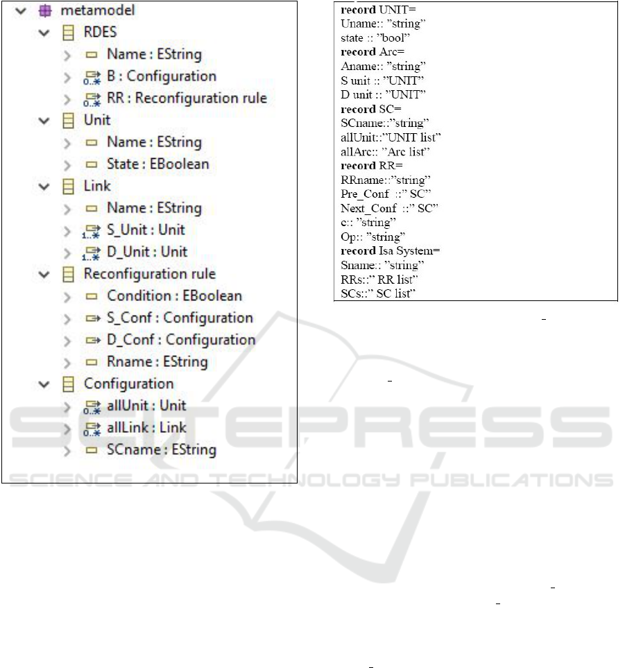
Figure 2: RDES Ecore Meta Model.
False}: the pr-condition of r
i
, (2) Operation is in-
cluding the addition/removal of units and links from a
source Con f
i
, to obtain a target Con f
j
configuration,
(3) S −Con f denotes the configuration Con f
i
before
the application of r
i
and (4) D−Con f denotes the tar-
get configuration Con f
j
after the reconfiguration rule
r
i
is applied. The reconfiguration rule r
i
for the trans-
formation from a Con f
i
to another Con f
j
configura-
tion, when we apply a reconfiguration scenario. If
Condition = True, r
i
is executable, otherwise it can-
not be executed. The transformation from Con f
i
to
Con f
j
. Figure 2 shows RDES Ecore Meta Model.
3.2 Isabelle/HOL Meta-model
An RDES consists of: a set of reconfiguration rules
to switch from a configuration to another. A con-
figuration is a stable situation that has a certain du-
ration in which a system performs an activity, i.e.,
system’s components are in a specific communication
with each other. We denote by SC: a configuration,
Figure 3: Isabelle formalization Isa System.
RR: a reconfiguration rule, and Unit: a component
of the system. We propose the Isabelle formalization
named Isa System shown in Figure 3. First, we de-
fine SC using records. SC contains: SCname is the
name of the SC, allU nit is the set of the units com-
posing the configuration (list of the type UNIT ), and
allArc is a list type Arc which represents all possi-
ble links between units. Type Arc is a record con-
tains: Aname is the name of the Arc, S − unit repre-
sents the source unit and D − unit represents the des-
tination unit, and Simple U NIT represents action in
line operation mode. The type UNIT is a record con-
sisting of: string the name of the unit and boolean
represents the state of unit. Reconfiguration rules RR
is defined by the record RR. A reconfiguration rule
consists of: the name of the rule, Pre Con f is the
precedent configuration, Next Con f is the next con-
figuration, and c is the condition and Op is the sting
represent a name of function apply to perform de next
configuration. Finally, we define FEST O MPS us-
ing Isa system record. A FESTO MPS consists of:
name of FESTO MPS, a set of RR type (reconfigu-
ration rules), and a set of SC type (system configura-
tions).
4 TRANSFORMATION FROM
ECORE MODEL TO
ISABELLE/HOL
In this section, we present the translation: from RDES
models into data structures used in Isabelle/HOL. We
Formalization and Verification of Reconfigurable Discrete-event System using Model Driven Engineering and Isabelle/HOL
253
detail one by one the different transformation rules.
Table 1 shows correspondences between ECORE and
Isabelle/HOL elements.
Table 1: Correspondences between Ecore and Isabelle/HOL
elements.
Ecore Isabelle/HOL
U={Unit i, ..., Unit j} record UNIT
L={Link ii, ..., Link j j} record Arc
B= {Con f
0
, Con f
1
, Con f
2
, record SC
..., Con f
i
, ..., Con f
n
}
RR = {r
i
,...,r
m
} record RR
RDES Ecore model record IsaSystem
• Transformation Process
The transformation consists of a set of transformation
rules. Each rule has the form:
Tr : Ecore model → Isabelle Types.
The first rule is Instance Epackage To Theory.
This rule triggers recursively other transformation
rules.
• Rule Instance EPackage To Theory
The components of the Ecore models are grouped
in EPackages. When we transform Ecore mod-
els into isabelle, we transform these packages
into theories (Theory). The name of an EPack-
age gives the name of the Theory. Additional
elements nsPrefix and nsURI are specific char-
acteristics of Ecore. They are neither translated
nor used in Isabelle. We call the rule by element
(TrMclass(),TrMAttribute(), TrMRe f erence(),
TrMgroup()) to translate type instances Eclassifiers
( Eclass, Ere f erence, EAttribute) contained in the
Epackage instance.
Tr (instance EPackage name = p
{ECl
1
... ECl
n
} = create Theory ();
set Name(p);
TrMcl (ECl
i
); / 0 i n
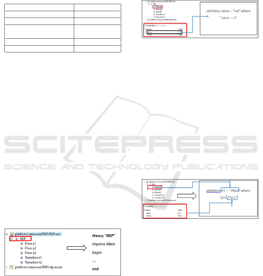
Figure 4: Rule Instance EPackage To Theory.
• Rule Instance EAttribute to Definition
If an EAttribute instance is formed of a primitive
type(int, bool, string), the transformation generates a
new definition. The name and value of this definition
are the same of EAttribute instance.
TrMAttribute (instance EAttribute name = a ,
value) =
create Type Definition () ;
set Name(a);
set Value(value)
Figure 5: Rule Instance EAttribute To Definition.
• Rule Instance EClass to Definition
The simplest case that we can face is how to trans-
form an EClass instance that is independent (i.e., not
linked with other EClasses). In this case, the EClass
is translated into a definition. The name EClass gives
the name of definition constructor. Then, for each in-
stance EStructural feature contained in the instance
EClass, we call the appropriate rule: TrMs f () to
transform the instances of the Structural Feature x
in (EAttribute, ERe f erence) type. TrMs f (x) is the
function that takes as input x and transforms it to Is-
abelle definition.
TrMclass (instance EClass name = c )
{ES f
i
...
E
S f
n
} = if (super Type = vide)
Create Definition();
set Name(c);
TrMs f (ES f
i
);/ 0 i n
Figure 6: Rule Instance EClass To Definition.
• Rule Instance EReference to Definition
In this case we use the same instructions as in the pre-
vious rule (Rule Instance EClass to definition), with a
simple modification, where the definition constructor
name will take the name of EReference Type.
TrMRe f erence (instance EReference name = c
{ES f
1
... ES f
n
}, eType =
Create Definition();
set Name(c);
TrMs f (ES f
i
);/ 0 i n
• The Regrouping Rule
This rule is made to regroup EReferences of the same
type in a single list. Therefore, we need to create a
ICSOFT 2020 - 15th International Conference on Software Technologies
254

list with the name of EReference, then we add all the
definitions of this EReference.
TrMgroup()=
List L=Create Liste();
if (containment =true or U pperBound =∗)
L.addAll (all definitions with the same construc-
tor)
When Tr() has a class instance of reconfiguration
rule, it is necessary to add complementary treatment
as follows: Create a new Isabelle function with the
reconfiguration rule name in order to make the neces-
sary changing in the system such as add/remove links
and units according to the rule.
5 VERIFICATION OF RDES
The next step after generating the RDES system in
Isabelle/HOL consists of improving the verification
by avoiding redundant computations. To this end, we
propose an algorithm that treats units and properties
to be verified. The main idea is to identify for each
configuration, related units that should be checked. A
unit should be checked only once in the proposed ver-
ification algorithm. Thus, from a configuration to an-
other, only the new unit should be verified. Mainly,
the algorithm consists of two steps:
• Step1: determines the difference between two sets
of units composing source and destination config-
urations.
• Step2: determines the properties that have rela-
tion with units selected in step1.
The Algorithm of verification (Algorithm 1) takes as
input three variables:
• PListe: represents the set of all properties to be
verified.
• Con f
i
Unit
i
(respectively Con f
j
Unit
j
):
represents the set of all units composing
con f iguration
i
(respectively con f iguration
j
).
And it gives as result two sets: set of units and set
of properties to be verified.
where,
• difference(list
1
, list
2
) is the function that takes as
inputs two lists list
1
, list
2
, and returns the differ-
ence between them;
• add(L, i) is the function that adds the item i to the
list L.
Algorithm 1: Verification Algorithm.
Input: PListe list properties,;
Con f
i
Unit
i
, Con f
j
Unit
j
: list UNIT;
Output: U,P;
U = difference (Con f
i
Unit
i
, Con f
j
Unit
j
);
/*U new set to save a result*/;
for Unit u
k
,k = 1..(U.size) do
for property p
q
,q = 1..(P.size) do
if exist a relation between: p
q
and u
k
then
add (P, item);;
/*P a new set to save a result*/;
end
end
end
6 APPLICATION TO FESTO
In this section, we apply the proposed approach to the
RDES in order to illustrate our contribution. First,
we present the production system FESTO as running
example. Second, we apply the proposed approach on
it.
6.1 Components & Working Process
FESTO consists of three stations: Distribution station,
Testing station and Processing station. The Distribu-
tion station is formed of a pneumatic feeder and a con-
verter which transmits cylindrical workpieces from a
stock to the Test station. The Test Station is composed
of a detector, a tester and an elevator. It performs tests
on workpieces for height, type of material and color.
Workpieces that satisfy these tests are transmitted to
the Processing Station, which is composed of a ro-
tating disk, a drill machine and a control machine.
The rotating disk is composed of locations to con-
tain and transport workpieces from the input position,
to the drilling position, to the control position and fi-
nally to the output position. We assume in this paper
that FESTO performs in different production modes
by using two drilling machines Driller1 and Driller2,
as follows:
• Light1 (respectively Light2): Only Driller1 (re-
spectively Driller2) is activated and used to drill
workpieces.
• Medium: Driller1 and Driller2 are activated but
used sequentially to drill workpieces (i.e., Driller1
or Driller2 works).
• High: Driller1 and Driller2 are activated and used
simultaneously to drill two pieces in the same
time.
Formalization and Verification of Reconfigurable Discrete-event System using Model Driven Engineering and Isabelle/HOL
255
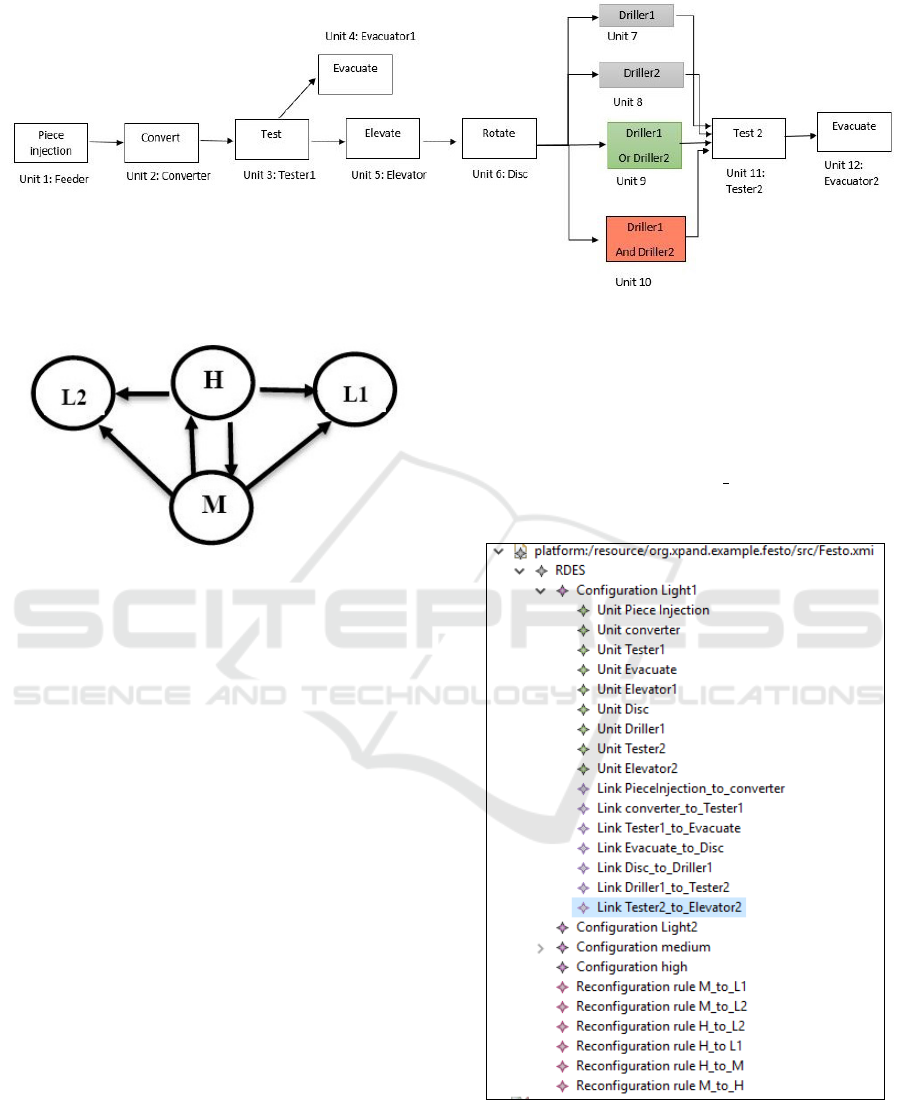
Figure 7: Working process of FESTO.
Figure 8: FESTO possible reconfiguration mode.
The system reconfigures in order to avoid any prob-
lem caused by a physical fault (i.e., when Driller1 or
Driller2 breakdown) or to answer user requirements.
The reconfiguration behavior of the studied system
loses its usefulness when both machines Driller1 and
Driller2 are broken. In the last case, the system totaly
stops. Figure 8 describes possible reconfigurations of
FESTO..
6.2 Production Lines
Based to the different production modes as shown in
Figure 7, FESTO behavior is represented by four pro-
duction lines such that each line is a list of described
as follows: Line1 represents the default production
mode Light1. After the work of Unit3, a workpiece
is moved to Unit4 or Unit5 according to the result
of the test station. Light2 is described by Line2.
Line3, line4 represent, respectively the medium and
high production modes of the FESTO system.
• Line1= Unit1; Unit2; Unit3; Unit5; Unit6;
Unit7; Unit11; Unit12.
• Line2= Unit1; Unit2; Unit3; Unit5; Unit6;
Unit8; Unit11; Unit12.
• Line3= Unit1; Unit2; Unit3; Unit5; Unit6;
Unit9; Unit11; Unit12.
• Line4= Unit1; Unit2; Unit3; Unit5; Unit6;
Unit10; Unit11; Unit12.
We denote by: L1, L2, M, and H, the four possible
system modes: Light1, Light2, Medium, and High,
respectively. As shown in Figure 8, the set of FESTO
RR are described as follow: RR
FEST O={r
1
(M,L1) ,
r
2
(M,L2) , r3(M,H), r
4
(H,L1) , r4(H,L2), r
5
(H,M)}
Figure 9: Model Ecore of our system.
ICSOFT 2020 - 15th International Conference on Software Technologies
256
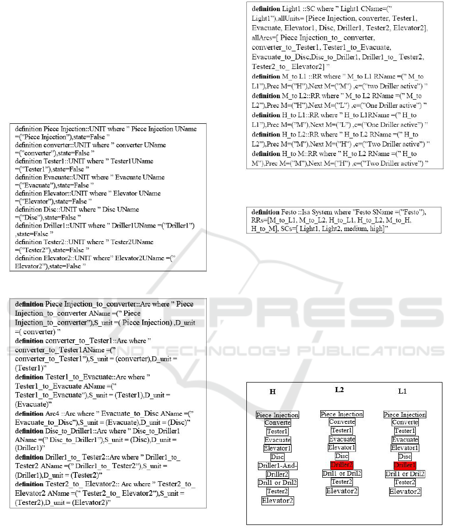
6.3 Formalization in Isabelle Tool
Figure 9 presents the Ecore model of our system in Is-
abelle tool. We apply the above transformation rules
to get the following result: the system component
(UNIT) shown in Figure 10, all possible links be-
tween units(Arc) shown in Figure 11, different con-
figurations (SC), reconfiguration rules (RR) shown in
Figure 12, and the complete system (Isa System) is
shown in Figure 13.
Figure 10: FESTO MPS Units Isabelle formalization.
Figure 11: FESTO MPS Arcs Isabelle formalization.
6.4 Verification
As shown in Figure 14, from the mode (H) to (L1)
(resp. (L2)), only Driller 1 (resp. Driller 2) need to
be checked, the unchanged units do not have to be
checked again. Furthermore, from the configuration
mode (M) to (L1) (resp. (L2)), only Driller 1 (resp.
Driller 2) need to be checked. Let us assume that
Figure 12: FESTO MPS configurations (SC), reconfigura-
tion rules (RR) Isabelle formalization.
Figure 13: FESTO MPS Isabelle formalization.
the user wants to switch the system to configuration
(H). In this case, the proposed algorithm of verifica-
tion searches in the set of the already checked units.
If a precedence relationship is found, then it is not
necessary to check it again. Otherwise, it will be for-
warded to the prover. The algorithm already deter-
mined the properties to be verified in the configura-
tion (L1), Therefore, it searches in the set of the al-
ready checked units about the properties is necessary
to verifier.
Figure 14: Verification of FESTO MPS.
Let us assume that FESTO is in Medium pro-
duction mode when the system receives requests to
change the production to Light1. If condition r (M,
L1) is satisfied, then the reconfiguration rule r(M, L1)
is executed automatically to respond to this request.
Using Isabelle tool we implement r(M, L1), where
Formalization and Verification of Reconfigurable Discrete-event System using Model Driven Engineering and Isabelle/HOL
257
we make the modification in the system, including
the remove of the unit Driller1-Or-Driller2 and add
the unit Unit7. The r (M, L1) means the switching
from Driller1 to line2. After, r (M, L1) is executed,
the workpieces are drilled by machine Driller1. In the
next, we present how to process a request, as follows:
Reconfiguration Rule M_to_L1!
If ((M_to_L1).c)then
Operation{
activated (Piece Injection)
activated (converter)
activated (Tester1)
activated (Evacuate)
activated (Elevator1)
activated (Disc)
add (Driller1)
remove (Dril1 or Dril2)
activated (Tester2)
activated (Elevator2)
}
End If
End
Where: activated (Unit i) represents the working of
the Unit i. For example, activated (Unit 2) means the
execution of the operation convert.
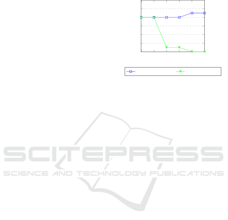
7 PERFORMANCE EVALUATION
Figure 15 shows two curves corresponding to the ver-
ification process with and without using our proposed
algorithm. The values of the abscises axis correspond
to the reconfigurations rules when the system runs two
times ((H to L1), (H to L2), (M to L1), (M to L2),
(M to H), (H to M))) in order. The ordinate axis cor-
respond to the number of checked units. The curve
in blue corresponds to the verification without pro-
posed algorithm. The curve in red corresponds to the
optimal verification using proposed algorithm. It is
important to note that the number of checked units
decreases gradually until the value zero when we use
the proposed algorithm. The reduction in the number
of units is followed by a reduction in the number of
properties.
8 CONCLUSION
This paper deals with the modeling and verification
of reconfigurable discrete event systems following
the MDE approach and using Isabelle/Hol theorem
prover. We define a Meta-Model to model RDESs
using MDE, we propose a new type Isabelle equiv-
alence to this Meta-model, and we establish the link
0 1 2 3 4
5
0
2
4
6
8
10
12
Reconfiguration rules
Number of Checked Units
without Algorithm. with Algorithm.
Figure 15: Comparison between verification process with
and without using the proposed algorithm.
between MDE and Isabelle by defining a set of re-
configurations rules to allow automatic generation of
system in Isabelle. Further more, once the system de-
scribed in Isabelle, we apply the verification process.
In order to avoid redundant computations, we propose
a new algorithm for optimal verification. In a future
work, we plan to reduce verification time of RDESs
by minimizing the number of properties. We plan also
to deal the correctness of the transformation itself by
describing both metamodels and transformation rules
in in Isabelle/HOL, then, use its theorem prover to
verify some properties that are preserved by the trans-
formation (Meghzili et al., 2019).
REFERENCES
Ali, T., Nauman, M., and Alam, M. (2007). An accessible
formal specification of the uml and ocl meta-model in
isabelle/hol. In 2007 IEEE International Multitopic
Conference, pages 1–6. IEEE.
Clarke, E. M., Henzinger, T. A., Veith, H., and Bloem, R.
(2018). Handbook of model checking, volume 10.
Springer.
Djeddai, S., Strecker, M., and Mezghiche, M. (2012). In-
tegrating a formal development for dsls into meta-
modeling. In International Conference on Model and
Data Engineering, pages 55–66. Springer.
Guellouz, S., Benzina, A., Khalgui, M., and Frey, G.
(2016). Reconfigurable function blocks: Extension to
the standard iec 61499. In 2016 IEEE/ACS 13th Inter-
national Conference of Computer Systems and Appli-
cations (AICCSA), pages 1–8. IEEE.
Hafidi, Y., Kahloul, L., Khalgui, M., Li, Z., Alnowibet, K.,
and Qu, T. (2018). On methodology for the verifica-
tion of reconfigurable timed net condition/event sys-
tems. IEEE Transactions on Systems, Man, and Cy-
bernetics: Systems.
Hafidi, Y., Kahloul, L., Khalgui, M., and Ramdani, M.
ICSOFT 2020 - 15th International Conference on Software Technologies
258

(2019). New method to reduce verification time of
reconfigurable real-time systems using r-tncess for-
malism. In International Conference on Evaluation
of Novel Approaches to Software Engineering, pages
246–266. Springer.
Jiang, Y., Liu, J., Dowek, G., and Ji, K. (2016). Sctl: To-
wards combining model checking and proof checking.
arXiv preprint arXiv:1606.08668.
Khalgui, M., Mosbahi, O., Hanisch, H.-M., and Li, Z.
(2012). Retracted article: A multi-agent architectural
solution for coherent distributed reconfigurations of
function blocks. Journal of Intelligent Manufacturing,
23(6):2531–2549.
Khalgui, M., Mosbahi, O., and Li, Z. (2019). On recon-
figuration theory of discrete-event systems: From ini-
tial specification until final deployment. IEEE Access,
7:18219–18233.
Khalgui, M., Mosbahi, O., Li, Z., and Hanisch, H.-M.
(2010). Reconfiguration of distributed embedded-
control systems. IEEE/ASME Transactions on Mecha-
tronics, 16(4):684–694.
Khlifi, O., Mosbahi, O., Khalgui, M., and Frey, G. (2015).
Gr-tnces: New extensions of r-tnces for modelling
and verification of flexible systems under energy and
memory constraints. In 2015 10th International Joint
Conference on Software Technologies (ICSOFT), vol-
ume 1, pages 1–8. IEEE.
Lewis, R. (2001). Modelling control systems using IEC
61499: Applying function blocks to distributed sys-
tems. Number 59. Iet.
Meghzili, S., Chaoui, A., Strecker, M., and Kerkouche, E.
(2017). On the verification of uml state machine di-
agrams to colored petri nets transformation using is-
abelle/hol. In 2017 IEEE International Conference on
Information Reuse and Integration (IRI), pages 419–
426. IEEE.
Meghzili, S., Chaoui, A., Strecker, M., and Kerkouche, E.
(2019). Verification of model transformations using
isabelle/hol and scala. Information Systems Frontiers,
21(1):45–65.
Zhang, J., Frey, G., Al-Ahmari, A., Qu, T., Wu, N., and
Li, Z. (2017). Analysis and control of dynamic recon-
figuration processes of manufacturing systems. IEEE
Access, 6:28028–28040.
Zhang, J., Khalgui, M., Li, Z., Mosbahi, O., and Al-Ahmari,
A. M. (2013). R-tnces: A novel formalism for recon-
figurable discrete event control systems. IEEE Trans-
actions on Systems, Man, and Cybernetics: Systems,
43(4):757–772.
Formalization and Verification of Reconfigurable Discrete-event System using Model Driven Engineering and Isabelle/HOL
259
