
Backstepping Controller Applied to a Foldable Quadrotor for 3D
Trajectory Tracking
Saddam Hocine Derrouaoui, Yasser Bouzid, Mohamed Guiatni, Halfaoui Kada, Islam Dib
and Noureddine Moudjari
Complex Systems Control & Simulators Laboratory, Ecole Militaire Polytechnique, Algiers, Algeria
Keywords:
Foldable Quadrotor, Robot, Design, Rotating Arms, Variable Geometry, Adaptive Morphology, Generic
Modeling, Control, Backstepping, PID.
Abstract:
This paper presents a novel design and architecture control of a foldable quadrotor. This design is based on
a variable geometry that can be changed during the flight. It is able to modify the orientation of its arms
independently, thanks to its special morphology. This quadrotor, exploits simple mechanisms i.e. rotating
arms. We stress that the control of this category of robots is not obvious compared to the conventional ones. So,
a detailed generic model and backstepping control that take into account the variation of the center of gravity
and the inertia are presented. Simulation results are also provided in order to illustrate the performances of
this controller.
1 INTRODUCTION
1.1 Literature Overview
Foldable quadrotors have gained extensive popularity
among scientists in recent years, thanks to their capac-
ities to adapt quickly their morphologies to different
flight conditions. They can perform critical tasks, dif-
ficult to perform with conventional quadrotors such
as, negotiation of vertical and horizontal narrow gaps,
flying in places more dangerous and difficult to ac-
cess, the inspection of sensitive points, discovery of
the caves and the transport of objects (Mintchev and
Floreano, 2016), (Floreano and Wood, 2015).
In (Ryll et al., 2015),(Nemati, 2016),(Kamel et al.,
2018), the authors concentrated their studies on mor-
phing aerial vehicles in which the propellers and ro-
tors tilt around their axes in order to overcome the
limitation of their mobility, improve their stability
and their control in flight. In works (Desbiez et al.,
2017),(Sanket et al., 2018), transformable quadro-
tors in flight were studied in order to negotiate small
openings or to transport objects. In paper (Riviere
et al., 2018), a quadrotor that can fold its structure
through a vertical or tilted window is proposed. The
PID controller was implemented to control the posi-
tion of the aerial robot. In article (Brescianini and
D’Andrea, 2016), the authors presented an omnidi-
rectional configuration allowing the quadrotor to ex-
ploit the dynamics of translation and rotation sepa-
rately. It is based on reversible actuators, which have
proven the feasibility of the design approach and the
ability of the vehicle to generate thrust and torque in-
dependently and in different directions. A multi-link
aerial robot has been presented in (Zhao et al., 2018)
where the joints are actuated slowly. A quadrotor,
with two independent rotating arms, is designed in
(Desbiez et al., 2017). A linear adaptive control is im-
plemented to deal with the changes of the inertia and
the center of mass. Bio-inspired design of quadrotors
has been investigated in reference (Mintchev et al.,
2018). This vehicle can deform during a collision
with obstacles to avoid damage by the use of specific
structural materials. Another design was presented
by (Avant et al., 2018) considering the rotation and
extension of the quadrotor arms dependently, which
hold in the event of a rotor failure in order to ensure
stable flight with three rotors. The PD and LQR con-
trollers were tested in simulation. Considering the ro-
tation of the quadrotor arms, (Xiong et al., 2019) are
interested in optimizing energy consumption during
the flight, which the attitude and the trajectory of the
prototype were controlled using two PID controllers.
The same principle is adopted in (Mintchev et al.,
2015),(Falanga et al., 2018) to focus later on special
configurations that are requested to cross vertical and
horizontal gaps. To ensure a stable flight, an adaptive
Linear Quadratic Regulation was applied in (Falanga
Derrouaoui, S., Bouzid, Y., Guiatni, M., Kada, H., Dib, I. and Moudjari, N.
Backstepping Controller Applied to a Foldable Quadrotor for 3D Trajectory Tracking.
DOI: 10.5220/0009890205370544
In Proceedings of the 17th International Conference on Informatics in Control, Automation and Robotics (ICINCO 2020), pages 537-544
ISBN: 978-989-758-442-8
Copyright
c
2020 by SCITEPRESS – Science and Technology Publications, Lda. All rights reserved
537
et al., 2018).
1.2 Contribution of This Work
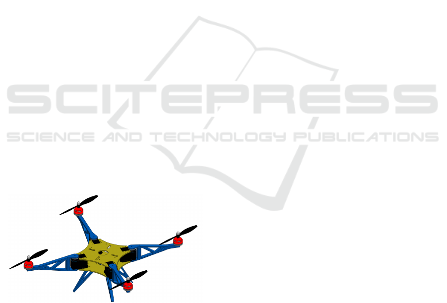
The proposed quadrotor (see Fig. 1), having for par-
ticularity the versatility in the execution of the tasks,
and especially those, which are dangerous and diffi-
cult such as, the mapping, the cross of small open-
ings, the navigation in congested spaces, the transport
objects, the inspection of cluttered environments and
for minimizing the consumed energy. This quadro-
tor, can be used also to flight with three rotors when
it has an anomaly in the one of the four rotors, which
it will be able to change quickly its configuration and
continuing the assigned mission.
We opted in the design on a simple mechanism of
rotation of the arms, which makes our quadrotor less
heavy and not complicate. The modeling and the con-
trol of this quadrotor is more challenging. Herein, we
seek to present a detailed generic model and backstep-
ping control strategy taking into account the dynam-
ics, the variation of the center of gravity, the variation
of the inertia, the variation of the allocation matrix
and aerodynamic effects during the flight.
2 MECHANICAL DESIGN AND
GEOMETRIC DESCRIPTION
As shown in Figures 1 and 2, our quadrotor is dif-
ferent to the classical platform. It can fold its arms
around a central body using very powerful and fast
servomotors, which allow a quick passage between
the various configurations.
Figure 1: Design of our proposed quadrotor, able to change
its configuration while flying. Each rotor is connected to a
rotating arm. Each rotating arm is connected to a servomo-
tor and it can rotate independently.
The chosen sequence of rotation is: the X Y Z se-
quence, meaning that the attitude is obtained first by
the roll angle ϕ, then by the pitch angle θ and then by
the yaw angle ψ. The obtained rotation matrix R is
given by:
R =
"
C
ψ
C
θ
C
ψ
S
θ
S
ϕ
− S
ψ
C
ϕ
C
ψ
S
θ
C
ϕ
+ S
ψ
S
ϕ
S
ψ
C
θ
S
ψ
S
θ
S
ϕ
+C
ψ
C
ϕ
S
ψ
S
θ
C
ϕ
−C
ψ
S
ϕ
−S
θ
C
θ
S
ϕ
C
θ
C
ϕ
#
(1)
where R ∈ SO(3) = {R ∈ R
3×3
|R
T
R = I
3×3
, det(R) =
1}. I
3×3
is the identity matrix of dimension 3 × 3.
S
(.)
and C
(.)
are abbreviations for Sin (.) and Cos (.)
respectively.
The designed quadrotor is composed of: a central
body of mass m
0
, four rotation servomotors attached
to the central body of mass m
1,i
, four rotating arms
attached to servomotors of mass m
2,i
and four rotor of
mass m
3,i
. Each component has its own body frame.
The four rotors are numbered 1, 2, 3 and 4, and
each arm is numbered according to the rotor fixed on
it. This quadrotor has two pairs of rotors, where two
rotors (2.4) spin in the clockwise direction whilst the
other two spin anticlockwise direction (1.3) (see Fig.
2). Each pair of rotors are placed on two opposite
sides of the airframe. We stress that the axes of rota-
tion of the rotors and the rotating arms are parallel to
z
b
axes (see Fig. 2). By changing the speed of the ro-
tors or the angles of the four arms, the quadrotor will
produce different motions (roll, pitch, yaw, altitude).
The throttle input M
T
is the sum of the thrusts gen-
erated by the four rotors. The direction of the thrust
produced by each rotor does not depend on the varia-
tion of the geometry. The moment around the body z
b
axis (M
z
) does not depend on the configuration, and
its expression is the same with standard quadrotor.
The main configuration leads to many other possible
configurations by changing either the angle of rotation
of the arms ψ
i
(t).
3 GENERIC MODELING
To model the foldable quadrotor, we based on multi-
body modeling approach taking into account all the
phenomena, because our system changes its morphol-
ogy while the flight according to the assigned task.
Since the majority of the configurations are not
symmetrical, so we will take into consideration that
the Center of Gravity (CoG) of the global system
moves, the global inertia matrix of the system varies,
the rotation of the arms also changes, which will push
us to develop a generic model.
The relation between the velocities and the exter-
nal forces and moments applied to center of grav-
ity, expressed in body frame, may be written using
Newton-Euler formalism as:
(2)
(
m
..
ξ
= F
T
+ F
D
+ F
G
I
Sys/O
(ψ
i
(t))
.
Ω
= −Ω ∧I
Sys/O
(ψ
i
(t))Ω +M
f
− M
a
− M
gy
ICINCO 2020 - 17th International Conference on Informatics in Control, Automation and Robotics
538
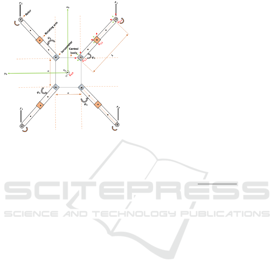
Figure 2: Schematic of our quadrotor.
where
ξ is the position of the quadrotor with respect to
the inertial frame.
m is the total mass of quadrotor structure.
Ω is the angular velocity of the airframe expressed
in b.
I
Sys/O
(ψ
i
(t)) is the quadrotor inertia during the
folding process, is calculated with respect to the geo-
metric center O of the body frame b and depends on
the variation of the rotation angle ψ
i
(t) of the arms.
F
T
is the resultant of the forces generated by the
four rotors:
F
T
= R.
0 0
4
∑
i=1
F
i
T
F
i
= K
l
ω
2
i
(3)
where K
l
is the lift coefficient and ω
i
is the angular
rotor speed.
F
D
is the resultant of the drag forces along (X, Y ,
Z) axes:
F
D
= diag
−K
Dx
−K
Dy
−K
Dz
.
ξ
(4)
where K
Dx
, K
Dy
, K
Dz
are the translation drag coeffi-
cients, respectively.
F
G
is the force of gravity:
F
G
=
0 0 −mg
T
(5)
where g is the gravity.
M
f
is the moment caused by the thrust and drag
forces. It is expressed as follows:
M
f
=
M
x
M
y
M
z
(6)
M
a
is the resultant of aerodynamic friction torques:
M
a
= diag
K
ax
K
ay
K
az
Ω
2
(7)
where K
ax
, K
ay
and K
az
are the aerodynamic friction
coefficients.
M
gy
is the resultant of torques due to the gyro-
scopic effects:
M
gy
=
4
∑
i=1
Ω ∧ J
r
0 0 (−1)
i+1
w
i
T
(8)
where J
r
is the rotor inertia.
3.1 Calculation of the Center of Gravity
The configurations of the quadrotor are not symmet-
rical. Thus, the CoG varies and has to be recomputed
when the configuration is changed. It is necessary to
put the general formula to calculate the CoG instanta-
neously, which depends on the masses and the varia-
tion of the centers of gravity of the other components
that we have mentioned before (see Fig. 2).
The formula is given as follows:
−→
OG =
4
∑
i=1
3
∑
j=1
m
j,i
−→
OG
j,i
m
0
+
4
∑
i=1
3
∑
j=1
m
j,i
(9)
with
−→
OG =
x
G
y
G
z
G
,
−→
OG
0
=
x
0
y
0
z
0
−−→
,OG
1,i
=
x
1,i
y
1,i
z
1,i
(10)
−→
OG
2,i
=
x
2,i
y
2,i
z
2,i
,
−→
OG
3,i
=
x
3,i
y
3,i
z
3,i
(11)
and
O : the geometric center (the origin of the body
frame).
−→
OG ∈ R
3×1
: the offset between the geometric
center of the system and the global center of gravity.
−→
OG
0
∈ R
3×1
: the vector of the center of gravity
of the central body which is zero.
−→
OG
1,i
∈ R
3×1
: the vector of the center of gravity
of the servomotors.
−→
OG
2,i
∈ R
3×1
: the vector of the center of gravity
of the rotating arms.
−→
OG
3,i
∈ R
3×1
: the vector of the center of gravity
of the rotors.
Backstepping Controller Applied to a Foldable Quadrotor for 3D Trajectory Tracking
539

3.2 Calculation of the Inertia
The calculation of inertia for any structure is not obvi-
ous. Therefore, some approximations should be set in
order to simplify the calculations. We assume that the
central body is a box of length and width a and height
h
0
. The servomotors are assumed rectangular cuboid
of length L
1
, width w
1
and height h
1
. The rotating
arms are also supposed rectangular cuboid of length
L, width w
2
and height h
2
. The rotors are supposed
cylinders of radius r and height h
3
.
We use the green body frame of each element (see
Fig. 2). We suppose that all the centers of gravity are
in the plan known as (O, x
b
, y
b
). The global inertia
matrix I
Sys/O
(ψ
i
(t)) depends to the angle of rotation
of each arm.
Using the parallel axis theorem, the calculation of
the inertia matrix is given as follows:
Inertia matrix of the central body:
I
(0)/O
= m
0
diag
a
2
+ h
2
0
12
,
a
2
+ h
2
0
12
,
2a
2
12
G
0
(12)
Inertia matrix of the servomotors:
I
(1,i)/O
= I
G
1,i
+ m
(1,i)
y
2
1,i
−x
1,i
y
1,i
0
−x
1,i
y
1,i
x
2
1,i
0
0 0 x
2
1,i
+ y
2
1,i
(13)
where
I
G
1,i
= m
(1,i)
diag
L
2
1
+ h
2
1
12
,
w
2
1
+ h
2
1
12
,
L
2
1
+ w
2
1
12
G
1,i
(14)
Inertia matrix of the rotating arms:
I
(2,i)/O
(Rot )
= R
z
(ψ
i
(t))I
(2,i)/O
R
z
(ψ
i
(t))
T
(15)
where
I
(2,i)/O
= I
G
2,i
+ m
(2,i)
y
2
2,i
−x
2,i
y
2,i
0
−x
2,i
y
2,i
x
2
2,i
0
0 0 x
2
2,i
+ y
2
2,i
(16)
I
G
2,i
= m
(2,i)
diag
L
2
+ h
2
2
12
,
w
2
2
+ h
2
2
12
,
L
2
+ w
2
2
12
G
2,i
(17)
and R
z
(ψ
i
(t)) ∈ R
3×3
is the rotation matrix on the z
b
axis.
Inertia matrix of the rotors:
I
(3,i)/O
(Rot )
= R
z
(ψ
i
(t))I
(3,i)/O
R
z
(ψ
i
(t))
T
(18)
where
I
(3,i)/O
= I
G
3,i
+ m
(3,i)
y
2
3,i
−x
3,i
y
3,i
0
−x
3,i
y
3,i
x
2
3,i
0
0 0 x
2
3,i
+ y
2
3,i
(19)
I
G
3,i
= m
(3,i)
diag
r
2
4
+
h
2
3
12
,
r
2
4
+
h
2
3
12
,
r
2
2
G
3,i
(20)
At the end, we get the global inertia matrix of the sys-
tem given by:
I
Sys/O
(ψ
i
(t)) = I
(0)/O
+
4
∑
i=1
I
(1,i)/O
+
4
∑
i=1
I
(2,i)/O
(Rot )
+
4
∑
i=1
I
(3,i)/O
(Rot )
(21)
3.3 Allocation Matrix
Roll and pitch moments
−→
M
x,y
are found from the cross
product. They depend on the variation of the rotation
angle ψ
i
(t) of each arm.
−→
M
x,y
=
4
∑
i=1
−→
GG
(3,i)
∧ F
i
−→
e
z
(22)
The relation between the thrust force total, the mo-
ments applied to CoG and velocities is given by:
M
T
M
x
M
y
M
z
= A
ω
2
1
ω
2
2
ω
2
3
ω
2
4
(23)
where
A =
K
l
K
l
(y
3,1
− y
G
) K
l
(−x
3,1
+ x
G
) K
d
K
l
K
l
(y
3,2
− y
G
) K
l
(−x
3,2
+ x
G
) −K
d
K
l
K
l
(y
3,3
− y
G
) K
l
(−x
3,3
+ x
G
) K
d
K
l
K
l
(y
3,4
− y
G
) K
l
(−x
3,4
+ x
G
) −K
d
T
(24)
and
x
3,1
=
a
2
+ (L + r)sinψ
1
(t)
x
3,2
=
a
2
+ (L + r)cosψ
2
(t)
x
3,3
= −
a
2
− (L + r)sinψ
3
(t)
x
3,4
= −
a
2
− (L + r)cosψ
4
(t)
y
3,1
= −
a
2
− (L + r)cosψ
1
(t)
y
3,2
=
a
2
+ (L + r)sinψ
2
(t)
y
3,3
=
a
2
+ (L + r)cosψ
3
(t)
y
3,4
= −
a
2
− (L + r)sinψ
4
(t)
(25)
M
T
is the thrust force total, M
z
is the yaw moment and
K
d
is the drag coefficient.
ICINCO 2020 - 17th International Conference on Informatics in Control, Automation and Robotics
540
4 CONTROL OF QUADROTOR
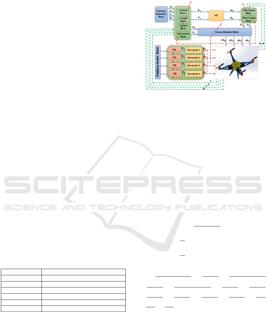
4.1 Control Architecture
In the literature, several recent works have used the
PID and LQR controllers (Desbiez et al., 2017),(Riv-
iere et al., 2018),(Avant et al., 2018),(Xiong et al.,
2019),(Falanga et al., 2018), due to the complexity
and the difficulty to control this type of quadrotors.
In this paper, our backstepping controller is de-
signed to ensure the tracking of the desired trajectory
(x
d
, y
d
, z
d
) along the three axes and the ψ
d
angle.
These reference trajectories are provided on-line by
a Trajectory Generator Block (TGB). The quadrotor
is controlled by the speeds of the four motors, these
speeds are deduced from the allocation matrix. The
CoG, the inertia matrix and the allocation matrix varie
and have to be recomputed on-line when the configu-
ration is changed.
The appropriate gains for each configuration of
the Backstepping controller are identified separately.
Then, we checked that the variation of the gains for
the intermediate configurations is not significant and
does not influence the desired dynamics. Conse-
quently, the gains change as soon as the servomotors
reach half of the desired positions. After identifica-
tion the gains, they will be injected into the different
controllers according to the current configuration.
The four servomotors are controlled indepen-
dently of the system by the PID controller (U
5
, U
6
,
U
7
, U
8
), their postions (ψ
1
(t), ψ
2
(t), ψ
3
(t), ψ
4
(t))
are sent to the control blocks and the allocation ma-
trix bloc to take them into account. The control struc-
ture scheme is shown in Figure 3. In our work, we
opted for six different configurations of the quadro-
tor, which changes them every 10 (sec) (see Table 1).
Table 1: Different configurations of our quadrotor.
Servomotors angles
Configuration 1 ψ
1
=π/4, ψ
2
=π/4, ψ
3
=π/4, ψ
4
=π/4
Configuration 2 ψ
1
=π/2, ψ
2
=0, ψ
3
=π/2, ψ
4
=0
Configuration 3 ψ
1
=π, ψ
2
=π, ψ
3
=π, ψ
4
=π
Configuration 4 ψ
1
=π/4, ψ
2
=π/4, ψ
3
=π/2, ψ
4
=0
Configuration 5 ψ
1
=π/2, ψ
2
=0, ψ
3
=π/4, ψ
4
=π/4
Configuration 6 ψ
1
=0, ψ
2
=π/2, ψ
3
=π/2, ψ
4
=0
4.2 Controller Design
In this part, we investigate the efficiency of the pro-
posed controller through and its application on our re-
configurable quadrotor, taking into account the varia-
tion of CoG, the inertia and the allocation matrix. The
controller is designed considering the model shown in
Figure 3: Control architecture.
(28) and applied to the generic model that we devel-
oped before in section 3.
The choice of the state vector is as follows:
X =
ϕ,
˙
ϕ,θ,
˙
θ,ψ,
˙
ψ,z, ˙z,x, ˙x,y, ˙y
T
(26)
such as:
X =
x
1
,x
2
,x
3
,x
4
,x
5
,x
6
,x
7
,x
8
,x
9
,x
10
,x
11
,x
12
T
(27)
˙x
1
= x
2
˙x
2
= a
1
x
4
x
6
+ a
2
x
4
Ω + b
1
U
2
+ c
1
x
2
2
˙x
3
= x
4
˙x
4
= a
3
x
2
x
6
+ a
4
x
2
Ω + b
2
U
3
+ c
2
x
4
2
˙x
5
= x
6
˙x
6
= a
5
x
2
x
4
+ b
3
U
4
+ c
3
x
6
2
˙x
7
= x
8
˙x
8
= −g +U
1
cos(x
1
)cos(x
3
)
m
+ c
4
x
8
˙x
9
= x
10
˙x
10
= U
1
U
x
m
+ c
5
x
10
˙x
11
= x
12
˙x
12
= U
1
U
y
m
+ c
6
x
12
(28)
where
a
1
=
I
yy
(ψ
i
(t))− I
zz
(ψ
i
(t))
I
xx
(ψ
i
(t))
, a
2
=
−J
r
I
xx
(ψ
i
(t))
, a
3
=
I
zz
(ψ
i
(t))− I
xx
(ψ
i
(t))
I
yy
(ψ
i
(t))
a
4
=
J
r
I
yy
(ψ
i
(t))
, a
5
=
I
xx
(ψ
i
(t))− I
yy
(ψ
i
(t))
I
zz
(ψ
i
(t))
, b
1
=
1
I
xx
(ψ
i
(t))
, b
2
=
1
I
yy
(ψ
i
(t))
b
3
=
1
I
zz
(ψ
i
(t))
, c
1
=
−K
ax
I
xx
(ψ
i
(t))
, c
2
=
−K
ay
I
yy
(ψ
i
(t))
, c
3
=
−K
az
I
zz
(ψ
i
(t))
, c
4
=
−K
Dz
m
c
5
=
−K
Dx
m
, c
6
=
−K
Dy
m
, Ω = ω
1
− ω
2
+ ω
3
− ω
4
The basic controller design procedure in our case is
performed in two steps.
Firstly:
The tracking error of the first subsystem is given:
e
1
= x
1d
− x
1
(29)
Its dynamics is described as follows:
˙e
1
= ˙x
1d
− x
2
(30)
Backstepping Controller Applied to a Foldable Quadrotor for 3D Trajectory Tracking
541

Let V
1
be a candidate positive definite Lyapunov func-
tion of the first subsystem and its derivative
˙
V
1
is neg-
ative definite:
V
1
=
1
2
e
1
2
(31)
˙
V
1
= −K
1
e
1
2
,K
1
> 0 (32)
Now, the asymptotic Lyapunov stability is guaran-
teed. For that, the virtual control law of the first sub-
system could be chosen as:
x
2d
= ˙x
1d
+ K
1
e
1
(33)
where e
2
is the tracking error of the second subsystem
given by:
e
2
= x
2d
− x
2
(34)
Secondly:
Let us augment the Lyapunov function expressed by
(31) as follows:
V
2
= V
1
+
1
2
e
2
2
(35)
where V
2
is positive definite. Its derivative:
˙
V
2
= −K
1
e
1
2
+e
2
[ ¨x
1d
+K
1
˙e
1
−a
1
x
4
x
6
−a
2
x
4
Ω−b
1
U
2
−c
1
x
2
2
]
(36)
with
˙
V
2
must be negative definite. To satisfy this con-
dition and ensure the Lyapunov stability, we choose
the control law U
2
as follows:
U
2
=
1
b
1
[ ¨x
1d
+K
1
˙e
1
−a
1
x
4
x
6
−a
2
x
4
Ω+K
2
e
2
−c
1
x
2
2
]
(37)
The next control laws U
1
, U
3
, U
4
, U
x
and U
y
, are ob-
tained by following the same steps presented above,
therefore:
U
1
=
m
cos(x
1
)cos(x
3
)
[g + ¨x
7d
+ K
7
˙e
7
+ K
8
e
8
− c
4
x
8
]
U
2
=
1
b
1
[ ¨x
1d
+ K
1
˙e
1
− a
1
x
4
x
6
− a
2
x
4
Ω + K
2
e
2
− c
1
x
2
2
]
U
3
=
1
b
2
[ ¨x
3d
+ K
3
˙e
3
− a
3
x
2
x
6
− a
4
x
2
Ω + K
4
e
4
− c
2
x
4
2
]
U
4
=
1
b
3
[ ¨x
5d
+ K
5
˙e
5
− a
5
x
2
x
4
+ K
6
e
6
− c
3
x
6
2
]
U
x
=
m
U
1
[ ¨x
9d
+ K
9
˙e
9
+ K
10
e
10
− c
5
x
10
]
U
y
=
m
U
1
[ ¨x
11d
+ K
11
˙e
11
+ K
12
e
12
− c
6
x
12
]
(38)
where K
2
, K
3
, K
4
, K
5
, K
6
, K
7
, K
8
, K
9
, K
10
, K
11
, K
12
are positive constants.
The servomotor controllers are given as follows:
U
5
= K
P5
e
5
+ K
I5
R
t
0
e
5
dt + K
D5
˙e
5
U
6
= K
P6
e
6
+ K
I6
R
t
0
e
6
dt + K
D6
˙e
6
U
7
= K
P7
e
7
+ K
I7
R
t
0
e
7
dt + K
D7
˙e
7
U
8
= K
P8
e
8
+ K
I8
R
t
0
e
8
dt + K
D8
˙e
8
(39)
where e
i
= ψ
id
− ψ
i
is the tracking error. K
Pi
,K
Ii
and
K
Di
denote the usual proportional integral derivative
tuning gains. They are positive constants.
where i=5,..,8.
4.3 Results and Discussion
We have developed a Matlab simulation environment
to evaluate the effectiveness of the proposed control
strategy applied to the quadrotor.
The results are displayed in Figures 4-5-6-7. We
have ploted separately, the tracking errors, the outputs
along x, y,z-axes, the attitude angles ϕ,θ, ψ, the ser-
vomotors outputs ψ
1
(t), ψ
2
(t), ψ
3
(t), ψ
4
(t) and the
control inputs U
1
, U
2
, U
3
, U
4
.
The effectiveness of this controller is investigated
in the variation of the geometry of the quadrotor each
10 (sec) while flying.
From the graphics shown in Figures 4-5, the
quadrotor follows its reference trajectory in a good
manner and satisfactory accuracy. The overshoot is
smallest on the ψ response. Moreover, it is clear that,
the backstepping controller ensures the continuity of
the control when switching between the different con-
figurations, with less consumed energy (see Fig. 4-6).
From Figure 7, the outputs of the four servomo-
tors follow the desired angles with some errors in the
descent and ascent.
Through the simulation results, we note that the
Backstepping controller adapts quickly to the varia-
tion of the configurations. It has proven its effective-
ness taking into account the variation of the CoG, the
variation of the inertia and the allocation matrix.
5 PROTOTYPE PLATFORM
In this section, we present the quadrotor platform that
we made in our laboratory (see Fig. 8). This proto-
type is under flight testing. To have a reconfigurable
structure, the quadrotor must rotate its arms. The ro-
tation of these arms is ensured by four servomotors
of type Dynamixel (see Fig. 8), which are controlled
in position and speed at the same time. The body an-
gular velocities are presented as p, q and r, which are
physically measured by three gyroscopes sensors in-
tegrated in the Pixhawk flight controller. To avoid the
collision of the propellers, we have proposed a solu-
tion to shift slightly each two adjacent rotors so that
the propellers never coincide.
ICINCO 2020 - 17th International Conference on Informatics in Control, Automation and Robotics
542
Figure 4: Quadrotor outputs.
Figure 5: Quadrotor errors.
Figure 6: Control inputs.
Figure 7: Servomotors outputs.
The realized quadrotor is characterized as follows
(see Table 2):
Table 2: Characteristics of our prototype.
Parameters Value
Global platform weight 1500 g
Arm lenght 21 cm
Central body length 12 cm
Central body width 12 cm
6 CONCLUSIONS AND FUTURE
WORK
We have presented a new architecture control and
generic modeling of a foldable quadrotor and its ap-
plications. This system has the ability to control the
orientation of its four arms independently. A new con-
Figure 8: Realized prototype. (1) Propeller. (2) Rotating
arm. (3) GPS. (4) Battery. (5) Pixhawk flight controller.
(6) Junction servo-arm. (7) Rotor. (8) Arduino card. (9)
Servomotor.
Backstepping Controller Applied to a Foldable Quadrotor for 3D Trajectory Tracking
543

trol strategy was applied taking into account the cal-
culation of the CoG, the inertia and the allocation ma-
trix instantaneously. The simulations have shown sat-
isfactory results of the Backstepping controller. The
flight test and implementation of the control laws are
in the final phase.
Adaptive control laws and optimization of the en-
ergy consumption will be treated in our future works.
REFERENCES
Avant, T., Lee, U., Katona, B., and Morgansen, K. (2018).
Dynamics, hover configurations, and rotor failure
restabilization of a morphing quadrotor. In 2018
Annual American Control Conference (ACC), pages
4855–4862.
Brescianini, D. and D’Andrea, R. (2016). Design, modeling
and control of an omni-directional aerial vehicle. In
2016 IEEE international conference on robotics and
automation (ICRA), pages 3261–3266.
Desbiez, A., Expert, F., Boyron, M., Diperi, J., Viollet, S.,
and Ruffier, F. (2017). X-morf: A crash-separable
quadrotor that morfs its x-geometry in flight. In 2017
Workshop on Research, Education and Development
of Unmanned Aerial Systems (RED-UAS), pages 222–
227.
Falanga, D., Kleber, K., Mintchev, S., Floreano, D., and
Scaramuzza, D. (2018). The foldable drone: A mor-
phing quadrotor that can squeeze and fly. IEEE
Robotics and Automation Letters, 4(2):209–216.
Floreano, D. and Wood, R. J. (2015). Science, technology
and the future of small autonomous drones. Nature,
521(7553):460–466.
Kamel, M., Verling, S., Elkhatib, O., Sprecher, C., Wulkop,
P., Taylor, Z., Siegwart, R., and Gilitschenski, I.
(2018). The voliro omniorientational hexacopter: An
agile and maneuverable tiltable-rotor aerial vehicle.
IEEE Robotics & Automation Magazine, 25(4):34–44.
Mintchev, S., Daler, L., L’Eplattenier, G., Saint-Raymond,
L., and Floreano, D. (2015). Foldable and self-
deployable pocket sized quadrotor. In 2015 IEEE In-
ternational Conference on Robotics and Automation
(ICRA), pages 2190–2195.
Mintchev, S. and Floreano, D. (2016). Adaptive morphol-
ogy: A design principle for multimodal and multi-
functional robots. IEEE Robotics & Automation Mag-
azine, 23(3):42–54.
Mintchev, S., Shintake, J., and Floreano, D. (2018).
Bioinspired dual-stiffness origami. Science Robotics,
3(20):eaau0275.
Nemati, A. (2016). Designing, modeling and control of a
tilting rotor quadcopter. PhD thesis, University of
Cincinnati.
Riviere, V., Manecy, A., and Viollet, S. (2018). Ag-
ile robotic fliers: A morphing-based approach. Soft
Robotics, 5(5):541–553.
Ryll, M., Bülthoff, H. H., and Giordano, P. R. (2015). A
novel overactuated quadrotor uav: Modelling, con-
trol and experimental validation. IEEE Transactions
on Control Systems Technology, Institute of Electrical
and Electronics Engineers, 23(2):510–556.
Sanket, N. J., Singh, C. D., Ganguly, K., Fermüller, C., and
Aloimonos, Y. (2018). Gapflyt: Active vision based
minimalist structure-less gap detection for quadro-
tor flight. IEEE Robotics and Automation Letters,
3(4):2799–2806.
Xiong, H., Hu, J., and Diao, X. (2019). Optimize energy
efficiency of quadrotors via arm rotation. Journal of
Dynamic Systems, Measurement, and Control, 141(9).
Zhao, M., Anzai, T., Shi, F., Chen, X., Okada, K., and
Inaba, M. (2018). Design, modeling, and control of
an aerial robot dragon: A dual-rotor-embedded multi-
link robot with the ability of multi-degree-of-freedom
aerial transformation. IEEE Robotics and Automation
Letters, 3(2):1176–1183.
ICINCO 2020 - 17th International Conference on Informatics in Control, Automation and Robotics
544
