
Survey and Preliminary Results on the Design of a Visual Light
Communication System for Radioactive and Underwater Scenarios
Giovanni Napoli
a
, Jos
´
e Vicente Mart
´
ı Avil
´
es
b
, Ra
´
ul Mar
´
ın Prades
c
and Pedro J. Sanz Valero
d
Interactive and Robotic Systems Lab, Jaume I University, Avda. Vicente Sos Baynat s/n, Castellon, Spain
Keywords:
Networked Robots, Communications, Visual Light Communications, Visual Feedback.
Abstract:
The use of radio-frequency communication systems is very well known and also it is broadly used in the
design of mobile robotics. In fact, it can be very well applied in rescue robotic systems, such as the ones
that present smoke and fire. In radioactivity scenarios the robot might get problems to communicate, in
the presence for example of magnets. Also, in underwater fields radio-frequency solutions need to improve
the communication distance, while sonar systems present variable delays and limited bandwidth, which are
difficulties to provide remote visual feedback to the operator. This paper states that field robotic systems,
such as the ones in radioactivity and underwater scenarios, need to complement the current communication
systems with multi-modal solutions, in order to enhance operation safety and reliability, while better adapting
to the mission unexpected situations. For this, Visual Light Communication solutions have been studied in
detail and a preliminary prototype, which is presented in this paper, has been designed. This prototype would
need further work to be applied successfully in real radioactive and underwater scenarios, as stated in the
conclusions.
1 INTRODUCTION
The TWINBOT project is a spanish research per-
formed in collaboration between the Girona Univer-
sity, University of Balearic Island, and Jaume I Uni-
versity of Castellon. The main focus of the project
is to go beyond the state of the art of mobile under-
water cooperative robots for manipulation, in order to
be able to solve robotic interventions which require
more than one robot at a time (e.g. transporting and
assembling big objects).
In order to be able to perform such a coopera-
tive interventions, it is necessary to work in order to
improve the way the robots communicate as a team,
and also to the surface. One of the communication
improvements to be faced is the use of wireless un-
derwater links. Previous experiences in this subject
(Centelles et al., 2020) demonstrated that radio fre-
quency modems can help to create a wireless com-
munication between the robots at a few meters, with
constant time-delay, and sonar system for linking to
the surface. These experiments demonstrated that it
a
https://orcid.org/0000-0003-2292-2260
b
https://orcid.org/0000-0001-9922-5733
c
https://orcid.org/0000-0002-2340-4126
d
https://orcid.org/0000-0003-3382-1553
is possible to send image feedback over these links
by using very specific communication protocols (Ru-
bino et al., 2017), and using a supervised control tech-
nique.
Sonar and radio-frequency channels offer limited
bandwidth (around 1-60 kbps), while being able to
transmit under low visibility conditions. Also, in or-
der to be able to transmit more information at short
distances, under good visibility conditions, the use of
Visual Light Communications has been studied and
experimented.
This paper is organized as follows. First of all a
survey on Visual Light Communication Systems for
underwater applications is presented. Secondly, the
design of a preliminar VLC prototype is presented,
which has as objective the demonstration of the con-
cept by using a low power laser, for safety reasons.
Third, the experiments with the VLC system are de-
scribed, presenting the low level protocol and the re-
sults of sending a dataset of 100 underwater images.
Finally, next steps on the design of the underwater
VLC system are presented.
Napoli, G., Avilés, J., Prades, R. and Valero, P.
Survey and Preliminary Results on the Design of a Visual Light Communication System for Radioactive and Underwater Scenarios.
DOI: 10.5220/0009889805290536
In Proceedings of the 17th International Conference on Informatics in Control, Automation and Robotics (ICINCO 2020), pages 529-536
ISBN: 978-989-758-442-8
Copyright
c
2020 by SCITEPRESS – Science and Technology Publications, Lda. All rights reserved
529

2 STATE OF THE ART
Emerging underwater communication technology de-
veloped for commercial sea resource exploration,
military warship-to-submarine communication, and
satellite-to-submarine communication is a challeng-
ing field of research. In fact, with the rapid ad-
vancement of technologies, different ways to com-
municate in an underwater environment have been in-
vestigated. Acoustic waves, radio-frequency electro-
magnetic (EM) waves, and visible EM waves are all
applicable for underwater communication. In partic-
ular, the first type suffers of high latency and low data
transmission rate (DTR) but has a very long range.
The second type has a very short range, up to meters,
and a quite good DTR, and the last has a very high
DTR and a range of tens of meters. These last two
suffer of absorption, which causes the low range, but
have almost no latency, and low signal-to-noise ratio
(SNR).
To have a better comprehension of the motivations
of this project, in the next sections there is a review
of related surveys about Underwater Optical Wire-
less Communication (UOWC) (Zeng et al., 2016) and
some background knowledge that could be useful for
the lasts sections.
2.1 Review of Related UOWC Surveys
In the last years, research has faced many challenges
in the UOWC field, and several articles have been
published to survey the subject. Khalighi et al. pre-
sented a brief review of some recent works on UOWC
in channel models, modulation and coding schemes,
and experimental works (Khalighi et al., 2014). Start-
ing from this analysis, they show the performance
study of a typical UOWC system with several simpli-
fied assumptions. Another study on UOWC channel
models has been carried on by Johnson et al. (John-
son et al., 2013a). Different typical UOWC modeling
methods such as Beer Lambert’s law, radiative trans-
fer function, and Monte-Carlo approach have been
discussed. Johnson et al. (Johnson et al., 2014) in-
troduced UOWC with a particular focus on aquatic
optical properties. Arnon (Arnon, 2010) analyzed the
link performance of a typical UOWC system and in-
troduced a number of challenging issues associated
with UOWC systems.
2.2 Background of UOWC
In this section, there are some background informa-
tion which constitute the basis of UOWC research.
First, the link configurations of UOWC will be pre-
sented. Second, the advantages and challenges of
UOWC will be highlighted. In the end, we summa-
rize the main works related to UOWC channel modu-
lations in [Table 1].
2.2.1 Link Configuration of UOWC
Based on link configurations, UOWC can be classi-
fied into four categories (Johnson et al., 2014): 1)
Point-to-point line-of-sight (LOS) configuration, 2)
Diffused LOS configuration, 3) Retroreflector-based
LOS configuration, and 4) Non-line-of-sight (NLOS)
configuration.
• Point-to-point LOS configuration is the most
commonly used in UOWC (Arnon, 2010). In
this configuration, the receiver detects the direc-
tion of the transmitter. It commonly employs light
sources, such as lasers with narrow divergence an-
gle, and so it requires a precise pointing between
transmitter and receiver which limits the perfor-
mance in turbulent water environments.
• Diffused LOS configuration employs diffused
light sources, such as high-power light-emitting
diodes (LEDs), with large divergence angle to ac-
complish broadcasting UOWC from one node to
multiple nodes. Broadcasting method can relax
the requirement of precise pointing. However,
compared with the point-to-point LOS configu-
ration, this link suffers from aquatic attenuation
due to the large interaction area with water. Rel-
atively short communication distances and lower
data rates are the two major limitations.
• Retro-reflector-based LOS configuration can be
seen as one special implementation of the point-
to-point LOS configuration. It is suitable for
duplex UOWC systems with underwater sensor
nodes having limited power and weight budget.
There is no laser or other light sources in the retro-
reflector end, and so, its power consumption, vol-
ume and weight are reduced. One limitation of
this configuration is that the back-scatter of the
transmitted optical signal may interfere with the
reflected signal, thus degrading the system signal-
to-noise ratio (SNR) and bit-error rate (BER).
Moreover, since the optical signals go through the
underwater channel twice, received signal will ex-
perience additional attenuation.
• NLOS configuration overcomes the alignment re-
striction of LOS UOWC. In this case, the trans-
mitter projects the light beam to the sea surface
with an angle of incidence greater than the criti-
cal angle. Therefore the light beam experiences a
total internal reflection (Arnon and Kedar, 2009).
ICINCO 2020 - 17th International Conference on Informatics in Control, Automation and Robotics
530

The receiver should keep facing the sea surface in
a direction parallel with the reflected light to en-
sure proper signal reception. The main challenge
of NLOS links is the random sea surface slopes in-
duced by wind or other turbulence sources (Tang
et al., 2013). These phenomena will reflect light
back to the transmitter implying severe signal dis-
persion.
2.2.2 Advantages and Challenges of UOWC
UOWC is characterised by many advantages over the
acoustic and RF methods, but achieving UOWC re-
mains as a challenging task. The main challenges of
UOWC are listed as follows.
• Optical signal suffers from severe absorption and
scattering. The wavelength of transmission light
has been selected in the blue and green spec-
trum to minimize the transmission attenuation ef-
fect (Duntley, 1963). This is due to the inevitable
photon interactions with the water molecules and
other particulate matters in water. Absorption and
scattering still severely attenuate the transmitted
light signal and cause multi-path fading. UOWC
suffers from poor BER performance over a few
hundred meters link distance in turbid water envi-
ronment. This is due to the impact of absorption
and scattering. In underwater environment, mat-
ters such as chlorophyll are capable of absorbing
the blue and red lights. These matters and other
colored dissolved organic material (CDOM) can
increase the turbidity and shrink the propagation
distance of the light. Moreover, the concentra-
tion of CDOM will also change with ocean depth
variations, thus modifying the corresponding light
attenuation coefficients (Johnson et al., 2013b).
These undesirable impacts will increase the com-
plexity of UOWC systems.
• Underwater optical links will be temporarily
disconnected due to misalignment of optical
transceivers. In many UOWC systems, blue/green
lasers or LEDs have been implemented as the
light sources for their narrow divergence fea-
ture. However, a precise alignment condition
is needed (Arnon, 2010). Since the underwa-
ter environment is turbulent at relatively shal-
low depths, link misalignment will take place
frequently, especially in the vertical buoy-based
surface-to-bottom UOWC applications (Johnson
et al., 2013b), (Yi et al., 2015). Random move-
ments of sea surface will cause serious connectiv-
ity loss problem (Dong et al., 2013a).
• The implementation of UOWC systems needs re-
liable underwater devices. The underwater envi-
ronment is complex: the flow, pressure, temper-
ature and salinity of seawater will strongly im-
pact the performance and lifetime of UOWC de-
vices (Pompili and Akyildiz, 2009). Furthermore,
if we consider that no solar energy can be ex-
ploited undersea and extended undersea operation
time of UOWC devices, the reliability of device
batteries and efficiency of device power consump-
tion are critical (Pompili and Akyildiz, 2009).
3 METHODS AND MATERIAL
This section is dedicated to the physical implementa-
tion of the prototype discussed previously.
The main instruments needed for the project are
two microprocessors whose interface is implemented
in Arduino code. We are going to describe in detail
why we have chosen these components and how we
have built the circuits. In the last part we will describe
more specifically the idea behind the software and the
protocols used.
3.1 Hardware Realisation
In this section we will analyse specifically the hard-
ware used. The main components are:
• Sipeed Maixduino
• Photo-diode
• Laser
Sipeed Maixduino. Maixduino (Figure 1) makes
the Arduino IDE and libraries support the Maix series
of development boards, making it easy to use a large
number of existing open source Arduino libraries for
rapid development and prototyping. We decided to
use this micro-controller because it is cheap, fast and
has a relatively large memory.
Photo-diode. Figure 2 shows the circuits needed to
develop a photo-diode receiver. It requires at least a
3.3V voltage supply, which can be performed by the
Maixduino board, and has as output a square wave.
Further information can be found here
1
.
Laser. We used an already implemented red-laser
diode (Figure 3) which has a power < 0.9mW and a
1
https://www.ebay.es/itm/EL0505-Receptor-
Detector-Laser-Arduino-modulo-sensor-no-modulado-
Rapsberry/331867336776
Survey and Preliminary Results on the Design of a Visual Light Communication System for Radioactive and Underwater Scenarios
531
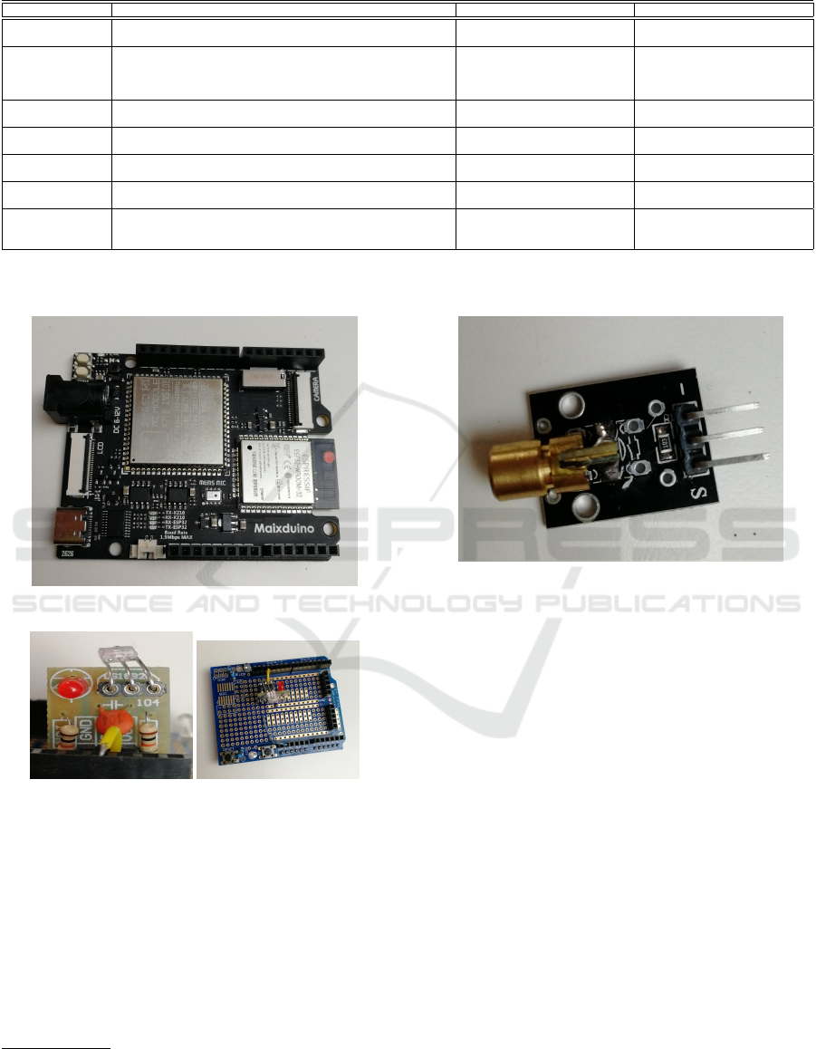
Table 1: Summary of Literature on UOWC Modulation Scheme.
UOWC modulations Literature Benefits Limitations
OOK
(Jaruwatanadilok, 2008),(Akhoundi et al., 2015), (Ahmad and Green,
2012), (Wang et al., 2012)
Simple and low cost Low energy efficency
PPM
(He and Yan, 2012), (Meihong et al., 2009), (Sari and Woodward,
1998), (Chen et al., 2006), (Anguita et al., 2010b), (Anguita et al.,
2010a), (Tang et al., 2012), (Swathi and Prince, 2014), (Hagem et al.,
2012)
High power efficency
High requirements on timing
Low bandwidth utilization rate
More complex transceivers
DPIM
(Gabriel et al., 2012), (Doniec et al., 2010a), (Doniec and Rus, 2010),
(Doniec et al., 2010b), (Mi and Dong, 2016)
High bandwidth efficency
Error spread in demodulation
Complex modulation devices
PSK (Cochenour et al., 2007), (Sui et al., 2009), (Cox et al., 2011) High receiver sensitivity
High implementation complexity
High cost
QAM (Cochenour et al., 2007)
High system spectral efficiency
Better rejection on noise
High implementation complexity
High cost
PolSK (Cox et al., 2009), (Dong et al., 2013b), (Zhang et al., 2012)
High tolerance to
underwater turbulence
Short transmission distance
Low data rate
SIM (Cox et al., 2011), (Cossu et al., 2013)
Increase system capacity
Low cost
Complex modulation/demodulation
devices and suffers from poor
average power efficiency
OOK - On-Off Keying; PPM - Pulse Position Modulation; DPIM - Digital Pulse Interval Modulation; PSK - Phase-Shift Keying; QAM - Quadrature Amplitude
Modulation; PolSK - Polarization Shift Keying; SIM - Subcarrier Intensity Modulation
Figure 1: Maixduino board.
Figure 2: On the left, the photo-diode and his shield; on the
right, the receiver’s shield.
voltage range between 0V and 5V. More information
can be found here
2
.
3.2 Software Implementation
The main structure of the project is shown in (Figure
4).
A computer controls the first Arduino that sends
messages using the laser to the second Arduino. This
2
https://www.ebay.es/itm/EL0478-Modulo-
Transmisor-LASER-5V-Rojo-650-nm-5mW-6mm-Diodo-
Arduino/231695187553
Figure 3: Laser.
one, through a serial communication, sends back to
the computer the information received via laser.
More specifically, a Python script has been created
to select an image from a dataset of size 100. Then, it
sends the image to Arduino through a serial port. This
Arduino unpacks the image and sends the information
to a second Arduino. This last channel is managed
via laser communication. The second Arduino has
the task of sending the received data to the computer
which analyses the final information.
3.2.1 Protocol
In this part we are going to describe specifically the
protocols used in our prototype. For sake of simplic-
ity we are going to refer to Figure 5.
• Firstly the transmitter and the receiver must syn-
chronise;
• The transmitter wakes up the Python program;
• The laptop sends the size of the images that must
be sent and waits for the same message to come
back to check it, then sends the data;
ICINCO 2020 - 17th International Conference on Informatics in Control, Automation and Robotics
532
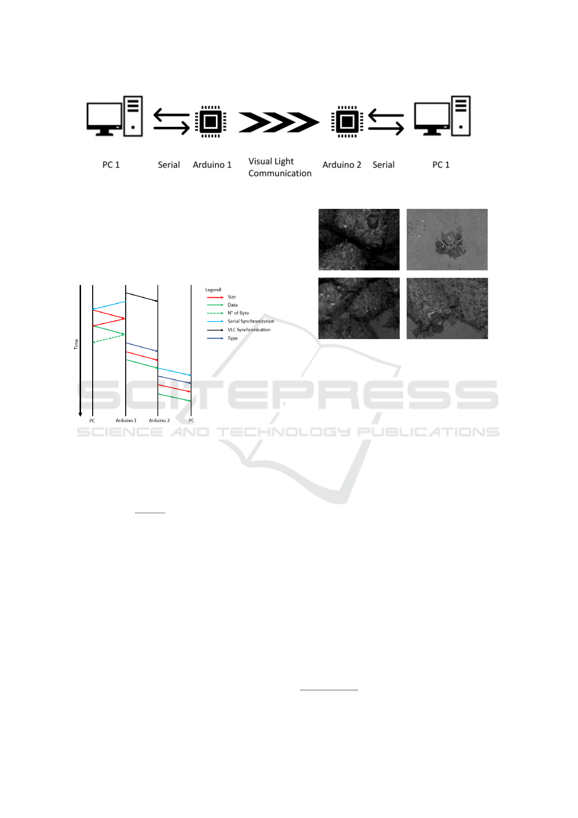
Figure 4: This is the setup scheme.
• The Arduino 1 sends the number of bytes received
to the laptop and then sends via VLC the type of
the message, its size and finally the data;
• The Arduino 2 receives the information and, once
the synchronisation with the laptop is done, sends
to it all the information;
Figure 5: Protocol.
3.2.2 Morse
We used the Morse Code as method to encode the
bit that must be sent via VLC. Specifically, we used
only a fraction of the sample, given by the equa-
tion sample =
1
f requency
, to identify zeros or ones.
So we used sample × 0.3 to identify a zero, and
sample × 0.7 to identify a one. This choice allowed
us to avoid many synchronisation problems but de-
creased the useful bandwidth.
4 EXPERIMENTAL SETUP
The following sections focus on the discussion, in-
terpretation and evaluation of the results obtained
through this study. The setup of the experiments can
be seen in Figure 7: the laptop is connected to the
Maixduino through a USB cable which sends via laser
the information received; in the other side of the alu-
minium bar there is the second Maixduino which re-
ceives the information via laser and sends them to the
Figure 6: Four images taken by the dataset Scott Reef 25.
laptop to check the data.
The data is composed of 100 images taken from
the dataset Scott Reef 25
3
(Figure 6), compressed and
resized to have different amount of Bytes. Finally
they have been converted in .txt file. This process,
useful for the data preparation, has been performed
using a Matlab script. The experiments have been
done in air and have been performed at four differ-
ent distances, using the six different sizes of images
(Table 2).
5 PRELIMINARY RESULTS
In this section we explain the results achieved through
the experiments described above. Using this proto-
type we reached a frequency of communication via
VLC of 2500 bit/s without losing big amount of data.
The experiments have been conducted for six differ-
ent cases, one for each size of the images, in which we
varied the distance between the laser and the photo-
diode, as can be observed in Figure 2. It is possible to
note that there are not significant differences between
the results obtained through the six experiments con-
ducted, meaning that the data received has not been
compromised by a variation of the distance between
the transmitter and the receiver. Moreover, it can be
noticed that also the size of the message does not im-
3
http://marine.acfr.usyd.edu.au/datasets/
Survey and Preliminary Results on the Design of a Visual Light Communication System for Radioactive and Underwater Scenarios
533
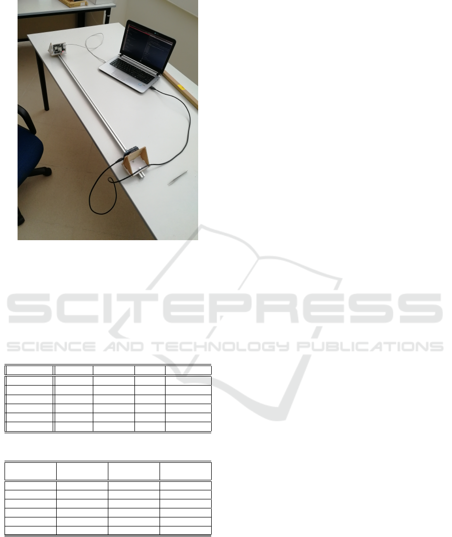
Figure 7: Experimental setup.
ply a loss of precision in the data received.
Another important consideration regards the time
it took for the receiver to get the messages. Re-
sults about the time variation for each experiments
are shown in Table 3: larger the size of the image,
the longer it takes.
Table 2: Percentage of errors for each size of each image
and distance (D).
Size (Bytes) D = 0 cm D = 25 cm D = 50 D = 100 cm
588 0 0 0 1
884 0 1 0 1
1610 1 0 1 1
2255 0 0 0 0
3536 1 0 0 1
6279 0 1 1 0
Table 3: Time spent to send a dataset of 100 images.
Size per
image (Bytes)
Total number
of Bytes sent
Time
Duration (s)
Bytes sent
per second
588 59300 500 118.6
884 88900 605 146.9
1610 161500 871 185.4
2255 226000 1109 203.8
3536 354100 1580 224.1
6279 628400 2689 233.7
6 CONCLUSION
In this paper the study of Visual-Light Communi-
cation methods for future underwater robotic appli-
cations have been presented. In fact, the paper fo-
cuses mostly on the presentation of the state of the
art, considering that wireless underwater communica-
tions need to be faced in a multimodal way. For exam-
ple, for long distances in open sea sonar is preferred,
while short distances can be faced via radio-frequency
links, which give constant time-delays, and laser-
based Visual-Light Communications under good vis-
ibility conditions.
Moreover, the paper shows a simple low-cost
method to implement a VLC system, which still needs
improvement in order to provide remote visual feed-
back. Further work will be focused on improving
the communication protocol in order to maintain the
reliability of the the system while obtaining greater
bandwidth for the transmission of real-time underwa-
ter images.
6.1 Further Steps in Underwater and
Radioactive Scenarios
In order to improve this system and apply it in under-
water scenarios it would be necessary to use a more
powerful laser, usually in the green band which, for
security reasons, must only be used inside the water,
confined in a sealed cylinder. The IRS Lab at UJI
have used similar lasers for underwater experiments
before, specially to create 3D maps from vision.
Also, for radioactive scenarios, the sealing is also
required in order to avoid the radioactive dust to get
into the electronics. These scenarios can use laser in
the red band for short distances.
In both cases it is mandatory to assure the align-
ment of the transmitter and receiver, so they have to
be mounted in a motorised pan-tilt device.
Further experiments will focus on this direction.
ACKNOWLEDGEMENT
It has been partially funded by the Spanish Govern-
ment under grants DPI2017-86372-C3 (TWINBOT),
Generalitat Valenciana under IDIFEDER/2018/013,
H2020 EU Peacetolero, and Jaume I University un-
der NEPTUNO project. The authors would like to ac-
knowledge the Australian Centre for Field Robotics’
marine robotics group for providing the data.
REFERENCES
Ahmad, Z. and Green, R. (2012). Link design for multi-hop
underwater optical wireless sensor network. In Proc.
Int. Conf. Syst. Netw. Commun.(IARIA), pages 65–70.
ICINCO 2020 - 17th International Conference on Informatics in Control, Automation and Robotics
534

Akhoundi, F., Salehi, J. A., and Tashakori, A. (2015). Cellu-
lar underwater wireless optical cdma network: Perfor-
mance analysis and implementation concepts. IEEE
Transactions on Communications, 63(3):882–891.
Anguita, D., Brizzolara, D., and Parodi, G. (2010a). Optical
wireless communication for underwater wireless sen-
sor networks: Hardware modules and circuits design
and implementation. In OCEANS 2010 MTS/IEEE
SEATTLE, pages 1–8. IEEE.
Anguita, D., Brizzolara, D., and Parodi, G. (2010b). Vhdl
modeling of phy and mac layer modules for under-
water optical wireless communication. In Proceed-
ings of Papers 5th European Conference on Circuits
and Systems for Communications (ECCSC’10), pages
185–188. IEEE.
Arnon, S. (2010). Underwater optical wireless communica-
tion network. Optical Engineering, 49(1):015001.
Arnon, S. and Kedar, D. (2009). Non-line-of-sight under-
water optical wireless communication network. JOSA
A, 26(3):530–539.
Centelles, D., Soriano, A., Marin, R., and Sanz, P. J. (2020).
Wireless hrov control with compressed visual feed-
back using acoustic and rf links. Journal of Intelligent
& Robotic Systems, 1(1):1573–0409.
Chen, M., Zhou, S., and Li, T. (2006). The implementa-
tion of ppm in underwater laser communication sys-
tem. In 2006 International Conference on Communi-
cations, Circuits and Systems, volume 3, pages 1901–
1903. IEEE.
Cochenour, B., Mullen, L., and Laux, A. (2007). Phase
coherent digital communications for wireless optical
links in turbid underwater environments. Technical re-
port, NAVAL AIR SYSTEMS COMMAND PATUX-
ENT RIVER MD.
Cossu, G., Corsini, R., Khalid, A., Balestrino, S., Coppelli,
A., Caiti, A., and Ciaramella, E. (2013). Experimental
demonstration of high speed underwater visible light
communications. In 2013 2nd International Workshop
on Optical Wireless Communications (IWOW), pages
11–15. IEEE.
Cox, W. C., Hughes, B. L., and Muth, J. F. (2009). A po-
larization shift-keying system for underwater optical
communications. In OCEANS 2009, pages 1–4. IEEE.
Cox, W. C., Simpson, J. A., and Muth, J. F. (2011).
Underwater optical communication using software
defined radio over led and laser based links. In
2011-MILCOM 2011 Military Communications Con-
ference, pages 2057–2062. IEEE.
Dong, Y., Tang, S., and Zhang, X. (2013a). Effect of ran-
dom sea surface on downlink underwater wireless op-
tical communications. IEEE Communications Letters,
17(11):2164–2167.
Dong, Y., Zhang, T., and Zhang, X. (2013b). Polarized
pulse position modulation for wireless optical com-
munications. In 2013 47th Annual Conference on In-
formation Sciences and Systems (CISS), pages 1–5.
IEEE.
Doniec, M., Detweiler, C., Vasilescu, I., Chitre, M.,
Hoffmann-Kuhnt, M., and Rus, D. (2010a). Aquaopti-
cal: A lightweight device for high-rate long-range un-
derwater point-to-point communication. Marine Tech-
nology Society Journal, 44(4):55–65.
Doniec, M., Detweiler, C., Vasilescu, I., and Rus, D.
(2010b). Using optical communication for remote un-
derwater robot operation. In 2010 IEEE/RSJ Interna-
tional Conference on Intelligent Robots and Systems,
pages 4017–4022. IEEE.
Doniec, M. and Rus, D. (2010). Bidirectional optical com-
munication with aquaoptical ii. In 2010 IEEE Interna-
tional Conference on Communication Systems, pages
390–394. IEEE.
Duntley, S. Q. (1963). Light in the sea. JOSA, 53(2):214–
233.
Gabriel, C., Khalighi, M.-A., Bourennane, S., L
´
eon, P., and
Rigaud, V. (2012). Investigation of suitable modula-
tion techniques for underwater wireless optical com-
munication. In International Workshop on Optical
Wireless Communications, pages 1–3.
Hagem, R. M., Thiel, D. V., O’Keefe, S. G., and Ficken-
scher, T. (2012). Optical wireless communication for
real time swimmers feedback: A review. In 2012 In-
ternational Symposium on Communications and In-
formation Technologies (ISCIT), pages 1080–1085.
IEEE.
He, X. and Yan, J. (2012). Study on performance of m-
ary ppm underwater optical communication systems
using vector radiative transfer theory. In ISAPE2012,
pages 566–570. IEEE.
Jaruwatanadilok, S. (2008). Underwater wireless op-
tical communication channel modeling and perfor-
mance evaluation using vector radiative transfer the-
ory. IEEE Journal on selected areas in communica-
tions, 26(9):1620–1627.
Johnson, L., Green, R., and Leeson, M. (2013a). A sur-
vey of channel models for underwater optical wireless
communication. In 2013 2nd International Workshop
on Optical Wireless Communications (IWOW), pages
1–5. IEEE.
Johnson, L. J., Green, R. J., and Leeson, M. S. (2013b).
Underwater optical wireless communications: depth
dependent variations in attenuation. Applied optics,
52(33):7867–7873.
Johnson, L. J., Jasman, F., Green, R. J., and Leeson,
M. S. (2014). Recent advances in underwater opti-
cal wireless communications. Underwater Technol-
ogy, 32(3):167–175.
Khalighi, M.-A., Gabriel, C., Hamza, T., Bourennane, S.,
Leon, P., and Rigaud, V. (2014). Underwater wireless
optical communication; recent advances and remain-
ing challenges. In 2014 16th International Conference
on Transparent Optical Networks (ICTON), pages 1–
4. IEEE.
Meihong, S., Xinsheng, Y., and Zhangguo, Z. (2009). The
modified ppm modulation for underwater wireless op-
tical communication. In 2009 international confer-
ence on communication software and networks, pages
173–177. IEEE.
Mi, X. and Dong, Y. (2016). Polarized digital pulse inter-
val modulation for underwater wireless optical com-
Survey and Preliminary Results on the Design of a Visual Light Communication System for Radioactive and Underwater Scenarios
535

munications. In OCEANS 2016-Shanghai, pages 1–4.
IEEE.
Pompili, D. and Akyildiz, I. F. (2009). Overview of net-
working protocols for underwater wireless communi-
cations. IEEE Communications Magazine, 47(1):97–
102.
Rubino, E. M., Centelles, D., Sales, J., Mart
´
ı, J. V., Mar
´
ın,
R., Sanz, P. J., and
´
Alvares, A. J. (2017). Underwater
radio frequency image sensor using progressive im-
age compression and region of interest. Journal of the
Brazilian Society of Mechanical Sciences and Engi-
neering, 1(1):4115–4134.
Sari, H. and Woodward, B. (1998). Underwater voice com-
munications using a modulated laser beam. In IEEE
Oceanic Engineering Society. OCEANS’98. Confer-
ence Proceedings (Cat. No. 98CH36259), volume 2,
pages 1183–1188. IEEE.
Sui, M., Yu, X., and Zhang, F. (2009). The evaluation of
modulation techniques for underwater wireless opti-
cal communications. In Proceedings of the Interna-
tional Conference on Communication Software and
Networks (ICCSN’09), pages 138–142.
Swathi, P. and Prince, S. (2014). Designing issues in de-
sign of underwater wireless optical communication
system. In 2014 International Conference on Com-
munication and Signal Processing, pages 1440–1445.
IEEE.
Tang, S., Dong, Y., and Zhang, X. (2012). Receiver de-
sign for underwater wireless optical communication
link based on apd. In 7th International Conference
on Communications and Networking in China, pages
301–305. IEEE.
Tang, S., Dong, Y., and Zhang, X. (2013). On path loss
of nlos underwater wireless optical communication
links. In 2013 MTS/IEEE OCEANS-Bergen, pages 1–
3. IEEE.
Wang, Z., Dong, Y., Zhang, X., and Tang, S. (2012). Adap-
tive modulation schemes for underwater wireless op-
tical communication systems. In Proceedings of the
Seventh ACM International Conference on Underwa-
ter Networks and Systems, page 40. ACM.
Yi, X., Li, Z., and Liu, Z. (2015). Underwater optical
communication performance for laser beam propaga-
tion through weak oceanic turbulence. Applied Optics,
54(6):1273–1278.
Zeng, Z., Fu, S., Zhang, H., Dong, Y., and Cheng, J. (2016).
A survey of underwater optical wireless communi-
cations. IEEE communications surveys & tutorials,
19(1):204–238.
Zhang, X., Dong, Y., and Tang, S. (2012). Polarization dif-
ferential pulse position modulation. In Proceedings of
the Seventh ACM International Conference on Under-
water Networks and Systems, page 41. ACM.
ICINCO 2020 - 17th International Conference on Informatics in Control, Automation and Robotics
536
