
An Integrated Object Detection and Tracking Framework
for Mobile Robots
William Kristian Juel
∗ a
, Frederik Haarslev
∗ b
, Norbert Kr
¨
uger
c
and Leon Bodenhagen
d
SDU Robotics, University of Southern Denmark, Campusvej 55, Odense C, Denmark
Keywords:
Detection, Visual Tracking, Mobile Robots, Perception System and Automation.
Abstract:
In this paper, we propose an end-to-end-solution to the problem of multi-object tracking on a mobile robot.
The tracking system consists of a process where we project 2D multi-object detections to the robots base
frame, using RGB-D sensor data. These detections are then transformed to the map frame using a localization
algorithm. This system predicts trajectories of humans and objects in the environment of the robot and can be
adapted to work with any detector and track from multiple cameras. The system can then be used to build a
temporally consistent costmap to improve navigation strategies.
1 INTRODUCTION
Mobile Robots are becoming an integrated part of
our society and are already making their ways around
factory floors, but they are also moving into uncon-
strained environments, filled with people and object,
as hospitals. For a mobile robot to seamlessly nav-
igate and manipulate within an unconstrained envi-
ronment, reasoning about the environment is impor-
tant. Mobile robots manipulate within an environ-
ment by finding the cheapest costs of a movement in
a costmap. The costmap gets information about ob-
stacles in the environment from the laser range sen-
sors and/or 3D cameras on the robot. In the classi-
cal methods, every obstacle is treated the same way
and there is no spatio-temporal nor semantic informa-
tion about each of these obstacles in the costmap. In
unconstrained environments, there can be a lot of hu-
mans and non-static objects, and because there is not
enough knowledge about these and their trajectory,
the robot fails to make an adequate decision when en-
countering them. We implement a system that pre-
dicts trajectories of humans and objects in the envi-
ronment of the robot, which can then be used to build
a temporally consistent costmap to improve naviga-
tion strategies. We refer to such a system as an object
a
https://orcid.org/0000-0001-5046-8558
b
https://orcid.org/0000-0003-2882-0142
c
https://orcid.org/0000-0002-3931-116X
d
https://orcid.org/0000-0002-8083-0770
∗
Equal contribution between the authors.
tracking system. A tracking system for a mobile robot
must be able to provide a target identity for the object
being tracked at each time-step. It should also be able
to perform well on a variety of sequences from differ-
ent environments and with a variation in the level of
crowdedness. Since the robots are moving, a tracking
system should be able to handle camera motion and to
some degree changes in illumination. Many, mobile
robots also have several cameras mounted, and there-
fore a tracking system should be able to utilize views
from multiple cameras. A tracker should be able to
function using a fixed set of parameters for every se-
quence in any type of environment so that installation
time is kept at a minimum (Leal-Taix
´
e et al., 2017), it
should also have a limited computational complexity
such that it can be run on embedded devices.
Most state-of-art tracking methods follow the
paradigm of tracking-by-detection. This is a two-step
process where first a frame-by-frame object detection
is required. Here learning-based detectors like (Red-
mon et al., 2015; Ren et al., 2015; He et al., 2017)
can be used or (Cao et al., 2018; Zhou et al., 2019)
if humans and their pose are of special interest. Sec-
ondly, the task is to determine inter-frame correspon-
dence between detections in order to predict trajecto-
ries. This is referred to as performing data association
where the quality of the matches between each de-
tected object per camera sequence is measured (Kim
et al., 2015; Rezatofighi et al., 2015; Wojke et al.,
2017; Son et al., 2017; Schulter et al., 2017).
The state-of-the-art benchmark for tracking sys-
tems is the MOT challenge (Voigtlaender et al., 2019).
Juel, W., Haarslev, F., Krüger, N. and Bodenhagen, L.
An Integrated Object Detection and Tracking Framework for Mobile Robots.
DOI: 10.5220/0009888405130520
In Proceedings of the 17th International Conference on Informatics in Control, Automation and Robotics (ICINCO 2020), pages 513-520
ISBN: 978-989-758-442-8
Copyright
c
2020 by SCITEPRESS – Science and Technology Publications, Lda. All rights reserved
513
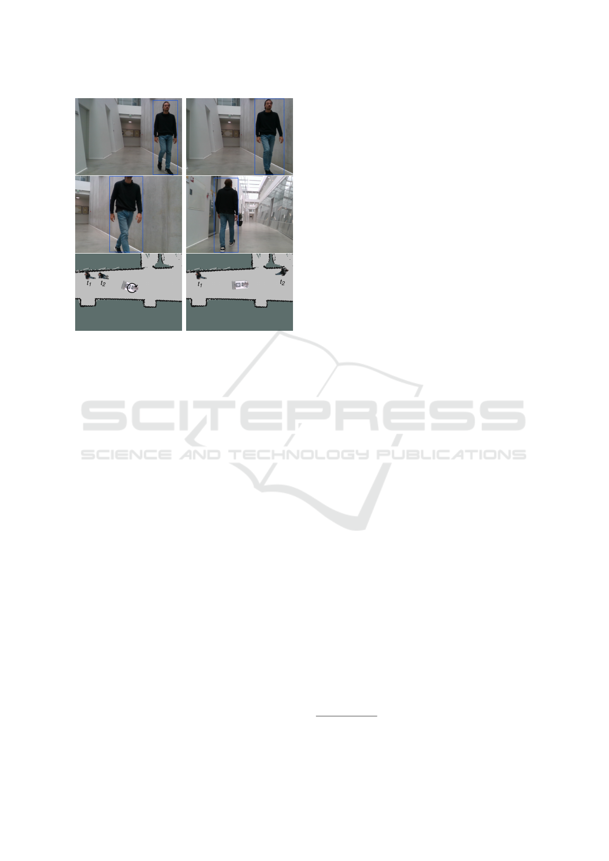
Figure 1: Two problems arising when using 2D tracking on
a mobile robot. Left column shows camera images before
and after the robot has rotated, causing a shift in the center
pixel of the person. Right column shows a person transi-
tioning from one camera to another, which is undefined in
image coordinates. Both are non-issues when tracking the
3D coordinates in the map frame. Here the before and after
are shown as time step t
1
and t
2
.
This challenge focuses on tracking in the image plane,
which might be a reason for most state-of-the-art
tracking systems being designed respectively. How-
ever, our 3D detection and tracking system tracks in
the map frame and not in the image plane. It esti-
mates the tracked identities absolute position in the
map frame, which is reliable even in cases where the
robot is moving as opposed to tracking in the im-
age plane. Mobile robots often have multiple cam-
eras mounted, and transitions between pixel coordi-
nates in different cameras are not well defined in 2D.
This is not the case for 3D since point clouds can be
transformed into other camera frames (given a cali-
bration) making the transition well defined. There-
fore, we change the state-space to the 3D position of
the detected object in the map frame (see fig. 1). By
using the map coordinates the robot can move while
the state of the objects does not change. In that way,
it will be able to use the tracked identities in robot
navigation tasks and general reasoning about the en-
vironment the robot manipulates with and in. Like-
wise, many of these 2D trackers are not designed with
computational complexity in mind, but instead with a
focus on scoring as high as possible on a benchmark
dataset. However, tracking systems deployed on mo-
bile robots must be able to run on embedded devices
such as a Jetson AGX XAVIER
1
. These two aspects
are essential to our implementation of the 3D detec-
tion and tracking system and therefore our contribu-
tion can be summarized as the following:
• We present a framework within the tracking-by-
detection paradigm by modifying a state-of-the-
art tracking algorithm to operate in the map frame.
This enables the framework to work with multi-
ple detectors operating on any number of cameras,
while only using a single global tracker.
• We show the framework working on a mobile
robot deployed in an unconstrained environment.
• We show that both the detector and tracker can run
online on the Jetson AGX XAVIER using multiple
cameras as input.
2 RELATED WORK
The tracking-by-detection paradigm divides the prob-
lem of multi-object tracking into two steps: (1) An
independent bounding-box detection of any object in
the scene – animate and inanimate – usually done us-
ing a convolutional neural network (CNN) such as
(He et al., 2017; Zhou et al., 2019; Cao et al., 2018).
(2) Data association, where a frame by frame linking
of all object instances detected in the scene is done
and each is assigned a trajectory that describes the
path of each of the object instances over time.
Traditionally, Multiple Hypothesis Tracking
(MHT) (Blackman, 2004) and Joint Probabilistic
Data Association (JPDA) (Rezatofighi et al., 2015)
have been used to solve the data association problem
in Multi-object tracking. However, the computation
times of these methods make them unfeasible for
online tracking - the complexity is exponential with
the number of object instances. In the following
section, we will focus on CNN detectors and tracking
algorithms that can track online.
2.1 Detectors
Since the introduction of AlexNet (Krizhevsky et al.,
2012), CNNs have been the state-of-art architecture
for image classification. Likewise, CNNs have shown
to work well for object detection and bounding box
prediction tasks. Object detection networks are usu-
ally divided into two different categories, two-stage,
and one-stage detectors. A widely used two-stage de-
tector is Faster R-CNN (Ren et al., 2015), which de-
1
https://www.nvidia.com/en-us/autonomous-machines/
embedded-systems/jetson-agx-xavier/
ICINCO 2020 - 17th International Conference on Informatics in Control, Automation and Robotics
514

tects objects by first proposing possible object bound-
ing boxes, then classifying the boxes as either con-
taining objects or not, and finally which type of ob-
ject it is. The Faster R-CNN architecture improves
on the computational complexity problems from ear-
lier versions (Girshick et al., 2013; Girshick, 2015)
by computing proposals with a CNN. Mask-RCNN
by (He et al., 2017) is an extension on Faster R-CNN,
that predicts a segmentation mask within the region
proposal. A segmentation mask like this could be use-
ful in a tracking system to feed the tracker with more
fine-grained information about the specific object and
in that way be able to ignore the background pixels.
Instead of detecting objects by region proposal
and classification, one-stage detectors like YOLO
(Redmon et al., 2015) and SSD (Liu et al., 2015) esti-
mates the bounding boxes in a single forward pass us-
ing anchors. One of the main problems with anchor-
based one-stage detectors is spatial constraints on the
bounding box predictions since each grid cell only
predicts a limited amount of boxes and only can have
one class. Another type of one-stage detector uses
keypoint detection to detect more than just the bound-
ing box of the objects. OpenPose (Cao et al., 2018) is
used specifically for humans, in that it uses heat maps
to detect joint locations, and part affinity fields to as-
sociate the key points to a single human. CenterNet
(Zhou et al., 2019) is a keypoint based one-stage de-
tector which expands on this idea. It uses keypoint
estimation to find the center pixel of detected objects,
and regression to estimate the width and height of the
bounding boxes. The architecture can easily be ex-
panded to regress to other object properties such as
3D pose, and can even be used for human pose estima-
tion by adding a joint keypoint head. The key points
are then associated with each center detection using
the regressed width and height of the bounding box.
All of these methods above facilitates a wide range
of flexible architecture designs, where a compromise
between runtime and mean Average Precision (mAP)
has to be made.
2.2 Tracking Algorithms
Tracking on a mobile robot must be done online while
the robot manipulates in its environment. Likewise,
the runtime of the tracker must be low enough so that
the robot has time to act and react to each tracked
object instance. Therefore, trajectories must be cal-
culated for each object instance on a frame-by-frame
basis. Due to the advancement in real-time object
detection, we theorize that using tracking algorithms
that focus on feature extraction from the detected ob-
ject instances is the best for deployment on a mobile
robot. Methods such as (Wojke et al., 2017; Son et al.,
2017) both exploit deep learning techniques.
In (Wojke et al., 2017) the tracking algorithm
DeepSORT uses a Kalman filter for state estimation
and the Hungarian algorithm to solve associations be-
tween the predicted Kalman states and new object
instances. They apply a siamese CNN with triplet
loss, that has been trained to discriminate between
humans. The triplet loss helps the network learn dif-
ferent feature vectors for different humans. This in-
creases the tracker’s robustness to misses and occlu-
sion while running at 40 Hz. In (Son et al., 2017)
a Quadruplet Convolutional Neural Networks (Quad-
CNN) is used for multi-object tracking, this learns to
associate the object instances across frames by using
quadruplet loss. This type of network consider object
appearances and temporal adjacencies for data asso-
ciation, Quad-CNN enforces temporally adjacent de-
tections to be more similar then the ones with large
temporal gaps.
3 3D DETECTION AND
TRACKING
The tracking framework proposed in this paper con-
sists of multiple components, communicating through
ROS (Stanford Artificial Intelligence Laboratory et
al., 2018). As per the tracking-by-detection paradigm,
the two major components are object detection mod-
ules and the tracking module. These are supported by
two utility modules: a camera gate that controls the
flow of images from multiple cameras to the different
detectors, and a map frame transformer which trans-
forms the detections to the map frame. Figure 2 shows
an overview of the framework. The code is available
at https://gitlab.com/sdurobotics/semantic map.
3.1 Capturing and Distributing Images
The developed framework is a visual tracking system,
and as such needs image and depth data in order to
detect and track objects in 3D. These images are pro-
vided by any number of RGB-D sensors. Any type
of RGB-D sensor works with the framework, as long
as it has ROS drivers that publish color images with
intrinsic camera parameters and a depth map with a
known transformation to the color image frame. The
images are used as input to the various detectors im-
plemented for the framework, but in many cases, it
does not make sense to use images from all cameras
as input for all detectors. Examples of this include
only detecting obstacles in the camera pointing in the
An Integrated Object Detection and Tracking Framework for Mobile Robots
515
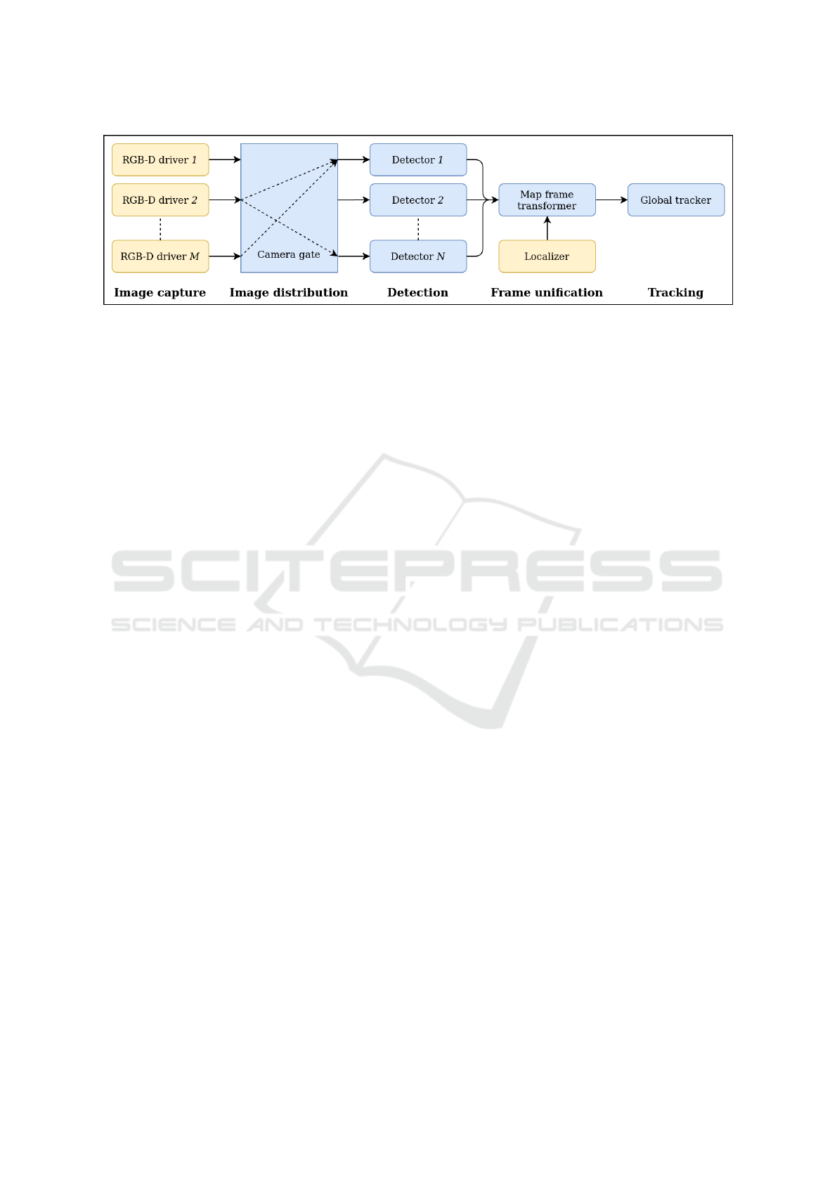
Figure 2: Flow of the tracking framework. Blue indicates modules implemented for the framework, where yellow is standard
modules available in ROS. Images from M RGB-D cameras are passed to a logic gate which can turn on/off passthrough to
each of the N detectors. The detectors process the received images as a batch and pass them to the map frame transformer
which unifies the coordinate frames using global localization information. The detections are then in the map frame and can
be tracked by the global tracker.
movement direction of the robot, or only detecting the
pose of an object of interest once the robot is near it.
To control this a camera gate module is imple-
mented, which can be used to open up an efficient
publisher/subscriber connection between a camera
and detector, using a simple ROS service call. The
service sends the intrinsic parameters of the selected
camera to the desired detector, adds the detector to
a list of connections for that camera, and then cre-
ates a subscriber to the camera if it was not created
previously by a service call for that camera and a dif-
ferent detector. Whenever a color and depth image
pair is published to the camera gate, it is immediately
republished to all detectors on the connection list of
that camera. A corresponding service call for delet-
ing connections is also implemented. It removes the
detector from the list of connections of that camera,
and if the list becomes empty the camera subscriber
is removed entirely. The next step is then to detect
objects in the color/depth image pair.
3.2 Detecting Object Properties
For the detection of objects, a versatile detector ROS
package has been implemented which can be config-
ured to detect a variety of object types. The task of the
detector is to detect each object of specific classes in
the color image, and then use the depth information to
derive each object’s 3D position or full 6-DoF pose,
along with optional keypoint information. Addition-
ally, the detector must also output a cropped image of
each object, as it is needed for the tracker as explained
in section 3.4. This is accomplished using Center-
Net (Zhou et al., 2019). CenterNet is a simple CNN
which can be configured for various detection tasks.
The authors of CenterNet have released models for a
2D bounding box, 3D bounding box, and human key-
point detection. In the simple case of 2D bounding
box detection, the pipeline is as follows: CenterNet is
used to detect the bounding box of each object in the
color image of the classes which it has been trained
to detect (fig. 3). For each detection, the detector now
uses the bounding box to crop the object image and
then transforms the bounding box to the depth image.
This enables the estimation of the objects 3D position
by finding the median depth in a small square around
the center of the bounding box and then projecting
it to 3D. The detector then outputs a ROS message
which for each object contains, their class, cropped
image, and 3D position. In case that multiple sensors
publish to the detector, then CenterNet processes all
color images as a batch in order to conserve comput-
ing resources. Afterward, each detection is processed
individually as previously stated, but using the depth
map corresponding to the color image where the de-
tection was made.
Besides the 2D bounding box network, the human
keypoint configuration of CenterNet has also been in-
tegrated with the detector. It functions in the same
way since it also provides a bounding box detection,
but additional to the 3D position, it also estimates the
torso direction of each detected human and the de-
tected keypoints in 3D. This is done by transforming
each keypoint to the depth image and projecting it
to 3D. The torso direction is then found as the vec-
tor orthogonal to the vector between the two shoulder
joints. The integration of the 3D bounding box detec-
tion configuration is also planned in the near future.
3.3 Unifying Detection Frames
Since the system supports multiple cameras, detec-
tions might have the same 3D position in their respec-
tive camera frames. E.g. an object 2 meter in front
of a robot’s front camera, has the same coordinates in
the front camera frame as an object 2 meter behind the
ICINCO 2020 - 17th International Conference on Informatics in Control, Automation and Robotics
516
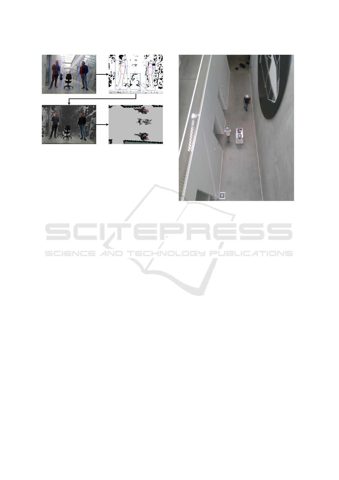
Figure 3: The flow of the two integrated detectors. The
bounding boxes for each object in the image is found, and
depending on the detector, keypoints as well. The detec-
tions are transformed to the depth map, and are then used to
estimate the 3D position of each object. The positions are
then transformed to the map frame. Along with the 3D po-
sition, the human keypoint detector also estimates the torso
direction as the vector orthonogal to the vector between the
projected shoulder joints.
robots back camera has in the back camera frame. In
order to distinguish these objects, their position needs
to be defined in a common frame. An idea could
be to transform each detection to the base frame of
the robot. This solves the ambiguity of the positions,
however, in case that the robot moves stationary ob-
jects will appear to move relative to it. This makes the
objects hard to track if the robot moves, as all objects
will appear to move in that way. Instead, each object
is transformed into the map frame using localization
data from e.g. the ROS navigation stack. This way
detections from different cameras have unique posi-
tions, which only changes based on the object’s own
movement, given a good localization. In reality, local-
ization is not perfect, which means that the positions
of the detection might jump in the map from one time
step to the next. It is then the job of the tracker to cor-
relate detections over time and estimate the objects’
true positions.
3.4 Tracking Object Instances
Until now each step in the framework happens with
no knowledge of the previous time step. This is not
the case for the tracker, which is used to assign IDs
to the detections while correcting the detected state of
the object. The tracker is based on DeepSORT (Wo-
jke et al., 2017), which uses a Kalman filter combined
with a deep association metric in order to track detec-
tions. The state space of the Kalman filter has been
changed to the 3D position of the object along with
Figure 4: Experimental setup viewed from the top-down
view camera: Reference marker on the ground-plan, Marker
on the robot and a marker on each test subject.
pose information if available. This enables the tracker
to smooth out detection noise and predict the move-
ment of objects if e.g. they move out of the field of
view of the camera. The deep feature used for associ-
ation is found by inputting the object image cropped
by the detector to a siamese CNN.
4 EXPERIMENTS
The robot used in the experiments has two Intel Re-
alSense cameras mounted – one in the front and one in
the back. Both are positioned 82 cm above the ground
plane. To asses the performance of the framework
we design an experimental setup where we mount a
camera in a top-down view in a hallway where the
robot is maneuvering. The test is limited to the field
of view of the top-down view camera. Ground truth
of trajectories are collected by mounting markers on
the test subjects and the robot and a stationary marker
is placed on the ground as a reference point for cali-
bration of the marker detection camera placement in
the map frame. The experimental setup is shown on
fig. 4, from the point of view of the marker detection
camera.
Different scenarios are tested where the robot is
either stationary or moving, and one or two test sub-
jects move around in either one of the cameras field
An Integrated Object Detection and Tracking Framework for Mobile Robots
517
(a) (b) (c) (d)
(e) (f) (g) (h)
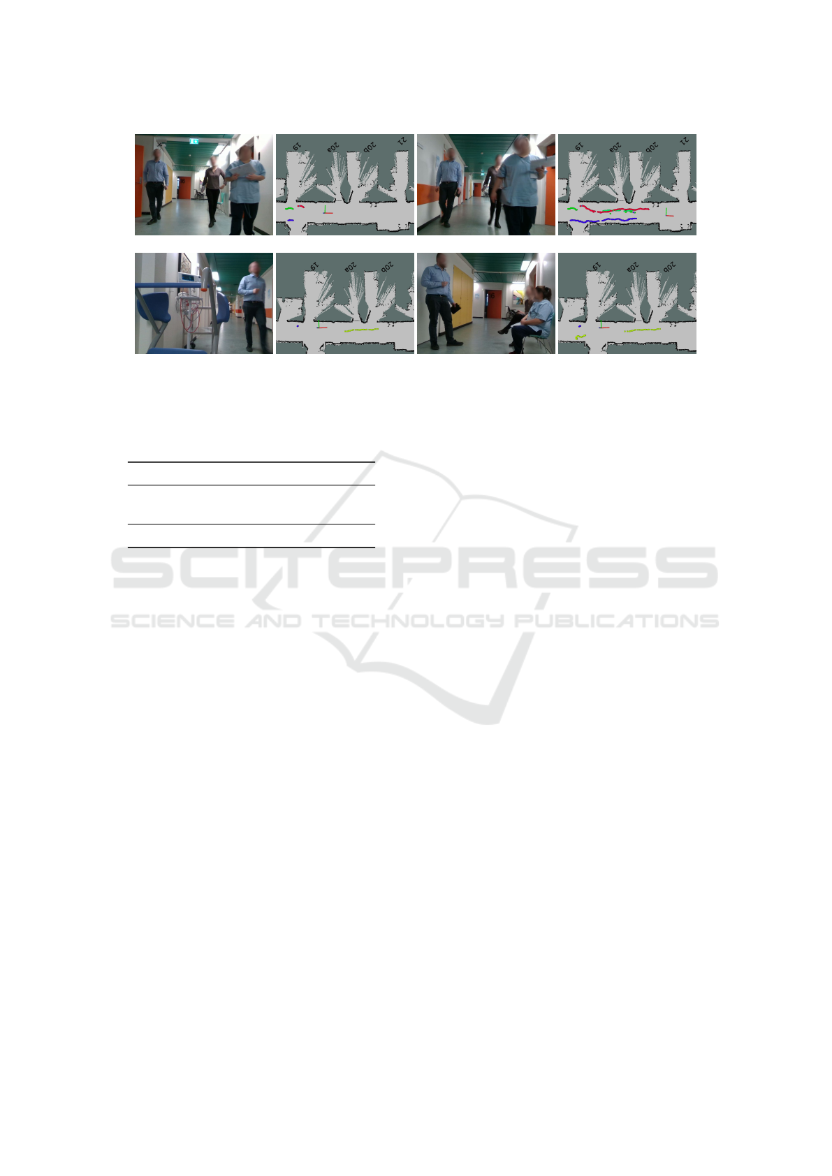
Figure 5: The image pairs on the left hand side (a)+(b) and (e)+(f) are initial trajectories where the image pairs on the right
hand side (c)+(d) and (g)+(h) are the final tracked trajectories. The color represents the ID of the track.
Table 1: Tracking results using the bounding box detector
with different backbones or the human keypoint estimator.
Detector MOTA ID Sw Frag
BBox-ResNet-18 0.740 9 5
BBox-DLA-34 0.725 10 7
Pose-DLA-34 0.742 19 6
of view, or both. The test is done using three differ-
ent detectors: two bounding box detectors with dif-
fering backbones (BBox-ResNet-18 and BBox-DLA-
34) and a human pose estimator (Pose-DLA-34). We
compute 40 individual trials consisting of a total of
6118 frames. Evaluation is carried out as suggested
in (Bernardin and Stiefelhagen, 2008) with the fol-
lowing metrics:
• MOTA. Multiple Object Tracking Accuracy,
measuring the combination of three error sources,
false positives, missed targets and identity
switches, as a value between 0-1.
• ID Sw. The number of identity switches.
• Frag. The number of times a trajectory is frag-
mented/interrupted during tracking.
The results from the evaluation can be seen on table 1.
Our results show that we have few identity
switches, between 9 and 19 over 6118 frames. This
shows that we maintain object identities through oc-
clusions, e.g., when the test subjects are in the robot’s
blind spots or when the test subjects occlude each
other during movement. Because of the appear-
ance information identities can be maintained through
longer occlusions. Likewise, the number of trajectory
fragmentations are below 8, which can be contributed
to the Kalman filter predicting the subject positions
while they are transitioning between cameras or oc-
clude each other. The MOTA is around 0.75 which in-
dicates we have a relatively low amount of false pos-
itives combined with few missed targets and identity
switches.
4.1 Real World Experiments
To asses the framework in an unconstrained environ-
ment we use data recorded on the same mobile robot
but operating in a hospital ward. This data does not
have ground truth associated with it and therefore we
do a qualitative assessment of the performance. The
test is visualized in a top-down view of the map at
the hospital ward. In the map, the robot position is
shown with a base link marker and the trajectory of
each tracked identity in the scene is marked with a
colored line (fig. 5b). Changes in the color of a con-
tinuous line thereby symbolizes an identity switch. In
figure 5 we see two examples of encounters with the
mobile robot.
In the first example, figs. 5a and 5b are the initial
measurement and figs. 5c and 5d are the final. Here
we see three people walking behind the robot while
it is driving. Generally the colored trajectory lines on
fig. 5d are stable. We observe zero identity switches,
although we can see that the two people walking on
the right-hand side of fig. 5c are walking in a line fol-
lowing a similar path (red and green), naturally the
person furthest behind (the green) will occasionally
be occluded by the person in front (the red). This oc-
clusion appears as fragmentation in the colored line,
which happens twice for the green line. After both oc-
clusions, the person is picked up by the tracker again
and given the same identity as before the occlusion.
The blue and the red line are continuous, each of the
ICINCO 2020 - 17th International Conference on Informatics in Control, Automation and Robotics
518

(a) (b)
Figure 6: (a) shows the trajectory before the person leaves
the field of view of the first camera and (b) shows the esti-
mated trajectory of the person while not in the field of view
of the robot and the measured trajectory when the person
enters the field of view again.
trajectories is only fragmented once. To summarise,
this first example shows that the tracker handles oc-
clusions well and can keep the identity even after a
short time of occlusion. This example also shows that
the tracker handles long continuous walking down a
hallway consistently.
In the second example, figs. 5e and 5f are the ini-
tial measurement and figs. 5g and 5h are the final.
Here the robot is not moving but parked at the side
of the hallway. Initially, we see one person walking
towards the robot on fig. 5e. This person’s measured
trajectory is the green line in figure fig. 5f. We also see
a blue line, which is a measured trajectory of a station-
ary person sitting behind the robot. On fig. 5g the per-
son has walked past the robot and enter into the cam-
era frame of the second camera, where we also see the
stationary people. On fig. 5h we can see that after the
person leaves the frame of the first camera, passes the
robot, and enters the field of view of the second cam-
era, he is picked up by the tracker and given the same
identity as before leaving the first camera frame. We
see that there are two stationary people, and only one
of them is detected and tracked, which is marked with
a blue line. This blue line is stable and does not flicker
which indicates that the tracker handles this situation
satisfyingly. In this example, zero identity switches,
and only one fragmented trajectory is observed when
the person leaves the camera frame before entering
into the view of the second camera. To summarise,
this second example shows that the tracker handles
the tracking of a person leaving the first camera frame
and entering the second camera frame well and can
keep the identity even after a short time of disappear-
ance. This type of fragmented trajectory, due to the
person leaving the field of view of one of the cam-
eras, can be handled by using the estimated states or
trajectories from the Kalman filter. In figure fig. 6 we
see the exact same example where one person leaves
the field of view of the robot and enters it again on
the other side (the predicted trajectory is now purple
instead of green). By including the estimated trajec-
Table 2: Run time evaluation of the framework using using
the bounding box detector with differing backbones, or the
human keypoint estimator. Each combination is tested using
1-4 cameras.
M cameras
Detector 1 2 3 4
BBox-ResNet-18 13.3Hz 11.5Hz 7.9Hz 5.9Hz
BBox-DLA-34 11.6Hz 9.2Hz 6.3Hz 4.8Hz
Pose-DLA-34 7.5Hz 5.1Hz 3.3Hz 2.6Hz
tories from the Kalman filter we see that the trajectory
is not fragmented when the person leaves the field of
view of the robot, because we continuously estimate
a linear velocity.
4.2 Run Time
To ensure that the framework can track online on em-
bedded robot hardware, we evaluate the run time of
our system on a Jetson AGX XAVIER. The test is
done using the three aforementioned detectors and a
1-4 camera configuration. The results of our run time
evaluation can be seen in table 2. From the results
we can see that the framework is computationally ef-
ficient and can operate in real-time on a mobile robot.
The environments that people interacting robots of-
ten operate in are rather slow-paced with humans and
many stationary objects. Here a run time of minimum
2.6Hz will be enough time to react to changes in the
environment.
5 CONCLUSION
We have presented an end-to-end-solution to the prob-
lem of multi-object tracking on a mobile robot. We
change the state-space of a tracking algorithm to
3D, and track 2D detections by transforming them to
the map frame using available depth and localization
data. Our experiments shows that we are able to track
through periods of occlusion, when people are transi-
tioning between different cameras and we predict re-
liable trajectories while the robot is moving. We ana-
lyze the run time of the system and show that it can be
used directly on mobile robot hardware. Our system
runs between 2.6-13.3Hz depending on detector and
camera configuration, making our system computa-
tionally efficient and able to track online on a mobile
robot.
An Integrated Object Detection and Tracking Framework for Mobile Robots
519

ACKNOWLEDGMENT
This research was supported by the project Health-
CAT, funded by the European Fund for regional de-
velopment, and by the project SMOOTH (project
number 6158-00009B) by Innovation Fund Denmark.
REFERENCES
Bernardin, K. and Stiefelhagen, R. (2008). Evaluating mul-
tiple object tracking performance: The clear mot met-
rics. EURASIP Journal on Image and Video Process-
ing, 2008.
Blackman, S. S. (2004). Multiple hypothesis tracking for
multiple target tracking. IEEE Aerospace and Elec-
tronic Systems Magazine, 19(1):5–18.
Cao, Z., Hidalgo, G., Simon, T., Wei, S., and Sheikh,
Y. (2018). Openpose: Realtime multi-person 2d
pose estimation using part affinity fields. CoRR,
abs/1812.08008.
Girshick, R. B. (2015). Fast R-CNN. CoRR,
abs/1504.08083.
Girshick, R. B., Donahue, J., Darrell, T., and Malik, J.
(2013). Rich feature hierarchies for accurate ob-
ject detection and semantic segmentation. CoRR,
abs/1311.2524.
He, K., Gkioxari, G., Doll
´
ar, P., and Girshick, R. B. (2017).
Mask R-CNN. CoRR, abs/1703.06870.
Kim, C., Li, F., Ciptadi, A., and Rehg, J. (2015). Multiple
hypothesis tracking revisited. pages 4696–4704.
Krizhevsky, A., Sutskever, I., and Hinton, G. E. (2012).
Imagenet classification with deep convolutional neu-
ral networks. In Proceedings of the 25th Interna-
tional Conference on Neural Information Processing
Systems - Volume 1, NIPS’12, page 1097–1105, Red
Hook, NY, USA. Curran Associates Inc.
Leal-Taix
´
e, L., Milan, A., Schindler, K., Cremers, D., Reid,
I. D., and Roth, S. (2017). Tracking the trackers: An
analysis of the state of the art in multiple object track-
ing. CoRR, abs/1704.02781.
Liu, W., Anguelov, D., Erhan, D., Szegedy, C., Reed, S. E.,
Fu, C., and Berg, A. C. (2015). SSD: single shot multi-
box detector. CoRR, abs/1512.02325.
Redmon, J., Divvala, S. K., Girshick, R. B., and Farhadi, A.
(2015). You only look once: Unified, real-time object
detection. CoRR, abs/1506.02640.
Ren, S., He, K., Girshick, R. B., and Sun, J. (2015). Faster
R-CNN: towards real-time object detection with re-
gion proposal networks. CoRR, abs/1506.01497.
Rezatofighi, S. H., Milan, A., Zhang, Z., Shi, Q., Dick, A.,
and Reid, I. (2015). Joint probabilistic data associa-
tion revisited. In 2015 IEEE International Conference
on Computer Vision (ICCV), pages 3047–3055.
Schulter, S., Vernaza, P., Choi, W., and Chandraker, M.
(2017). Deep network flow for multi-object tracking.
CoRR, abs/1706.08482.
Son, J., Baek, M., Cho, M., and Han, B. (2017). Multi-
object tracking with quadruplet convolutional neural
networks. In 2017 IEEE Conference on Computer Vi-
sion and Pattern Recognition (CVPR), pages 3786–
3795.
Stanford Artificial Intelligence Laboratory et al. (2018).
Robotic operating system.
Voigtlaender, P., Krause, M., Osep, A., Luiten, J.,
Sekar, B. B. G., Geiger, A., and Leibe, B.
(2019). Mots: Multi-object tracking and segmenta-
tion. arXiv:1902.03604[cs]. arXiv: 1902.03604.
Wojke, N., Bewley, A., and Paulus, D. (2017). Simple on-
line and realtime tracking with a deep association met-
ric. CoRR, abs/1703.07402.
Zhou, X., Wang, D., and Kr
¨
ahenb
¨
uhl, P. (2019). Objects as
points. CoRR, abs/1904.07850.
ICINCO 2020 - 17th International Conference on Informatics in Control, Automation and Robotics
520
