
Functional Architecture using ROS for Autonomous UAVs
Johvany Gustave, Jamy Chahal and Assia Belbachir
Department of Aerospace Systems, IPSA, Ivry-Sur-Seine, France
Keywords:
Functional Architecture, UAV, Quadrotor, ROS.
Abstract:
Unmanned Aerial Vehicles (UAVs) are used for several applications due to their stability and versatility. In this
paper, we developed a functional architecture for autonomous UAVs using Robot Operating System (ROS).
Due to its flexibility and its easy-to-use implementation, our architecture simplifies embedding autonomous
behaviours for any kind of UAV. This hierarchical architecture is divided into three layers: decision, control
and perception layer. In this paper, all the layers and their implementation under ROS are explained and
detailed.
1 INTRODUCTION
Nowadays, the application of Unmanned Aerial Ve-
hicles (UAV) also called drones covers a growing
scope. Drones are especially prized for being cost
effective, stable, semi or fully autonomous and able
to carry loads. Indeed, with only some motors gener-
ating lift in the same direction, control theory allows
drones to perform specific behaviour like hovering,
going to a specific position, following a path, turn-
ing in circle around a point etc. Besides, drones can
embed several sensors such as LIDAR, camera mono,
stereo, or sonar depending on their mission. Several
drone missions such as search and rescue (Misra et al.,
2020), monitoring (Wang et al., 2019) or exploration
(Maciel-Pearson et al., 2019) has been developed and
experimented.
In (Misra et al., 2020), the authors developed a
swarm cooperative UAVs to perform selective explo-
ration. This approach is applied in search and res-
cue to improve ground survivor’s detection. In (Wang
et al., 2019), the authors propose the use of UAV with
high resolution camera to monitore the ocean envi-
ronment. The method of superpixel and Convolu-
tional Neural Networks (CNNs) is used to improve
the supervision of seaweed proliferation. In (Maciel-
Pearson et al., 2019), the authors developed an au-
tonomous UAV to explore an outdoor environment
with deep reinforcement learning. This approach use
Deep Q-Network to reduce exploration time.
UAVs are also used for missions which are dan-
gerous and locations which are hard to access for hu-
mans. To perform these missions, UAVs can be re-
motely operated or fully autonomous. Autonomous
UAVs need a robust functional organization in or-
der to perform an interaction between the sense (sen-
sors), the flight’s stabilization while reaching the de-
sired location (controller) and the decision making
(depending on the strategy). The organization rely
on a sturdy architecture certifying the coaction’s ef-
ficiency of all software components and the system’s
robustness. Thus, we can find in the literature several
types of functional architectures such as the subsump-
tion architecture (Brooks, 1986), hierarchical archi-
tecture (Alami et al., 1998), etc. More details on the
pros and cons for UAV’s architecture was explained
in (Asmaa et al., 2019).
In this article, we have decided to develop a hierar-
chical architecture for its robustness and its easy im-
plementation using Robot Operating System (ROS)
This hierarchical architecture allows our UAV to or-
ganize the commands into three levels. Each level has
its own role and its own importance. Higher is the
level, higher is its goal. High level (decision) has in-
formation related to the whole mission thus it has a
higher reasoning time. However the lower level has a
reduced time to reason but is more reactive in a short
term mission, such as avoiding obstacles. The aim of
this framework is to be flexible for any kind of UAV
and missions. We rely on Gazebo’s simulator
1
to val-
idate the proposed architecture.
ROS is an open source Meta-Operating System
providing an ecosystem and a set of tools for robotics
application. ROS allows the communication between
programs, called nodes. This communication is cen-
tralized around a single node called the master. Each
1
http://gazebosim.org
506
Gustave, J., Chahal, J. and Belbachir, A.
Functional Architecture using ROS for Autonomous UAVs.
DOI: 10.5220/0009888305060512
In Proceedings of the 17th International Conference on Informatics in Control, Automation and Robotics (ICINCO 2020), pages 506-512
ISBN: 978-989-758-442-8
Copyright
c
2020 by SCITEPRESS – Science and Technology Publications, Lda. All rights reserved
node shares continuously through topic a structured
data called message. Nodes can also use services to
send request with the client-server relationship. Due
to its structure, ROS implementation is robust, exten-
sible and benefits from graphic tools analysis.
Developing a functional architecture in a stable
framework such as ROS, ensures to get a reliable sys-
tem. This association has been done with the sub-
sumption architecture in (Li et al., 2016; Yi et al.,
2016), and with the T-Rex architecture (Mcgann et al.,
2008). Hierarchical architecture has only been ex-
perimented with ROS for domestic robot’s planning
(Janssen et al., 2013). Nonetheless, this implementa-
tion was generic and not developed for UAVs.
In this paper we present our developed architec-
ture which is divided into three layer: perception
(lower layer), control (middle layer) and decision
layer (higher layer). This architecture is implemented
for the fire localization use case.
The validation of the approach was already done
in (Belbachir and Escareno, 2016), however, the ar-
chitecture was not implemented into an UAV. Thus, in
this article, we propose to extend the previous explo-
ration strategy into our functional architecture based
on ROS.
This paper is organized as follows. Section II ex-
plains the design of the framework for UAV’s applica-
tion. Section III details how this framework is imple-
mented. Section IV provides conclusions and future
work to be done.
2 FUNCTIONAL
ARCHITECTURE FOR
AUTONOMOUS QUADROTOR
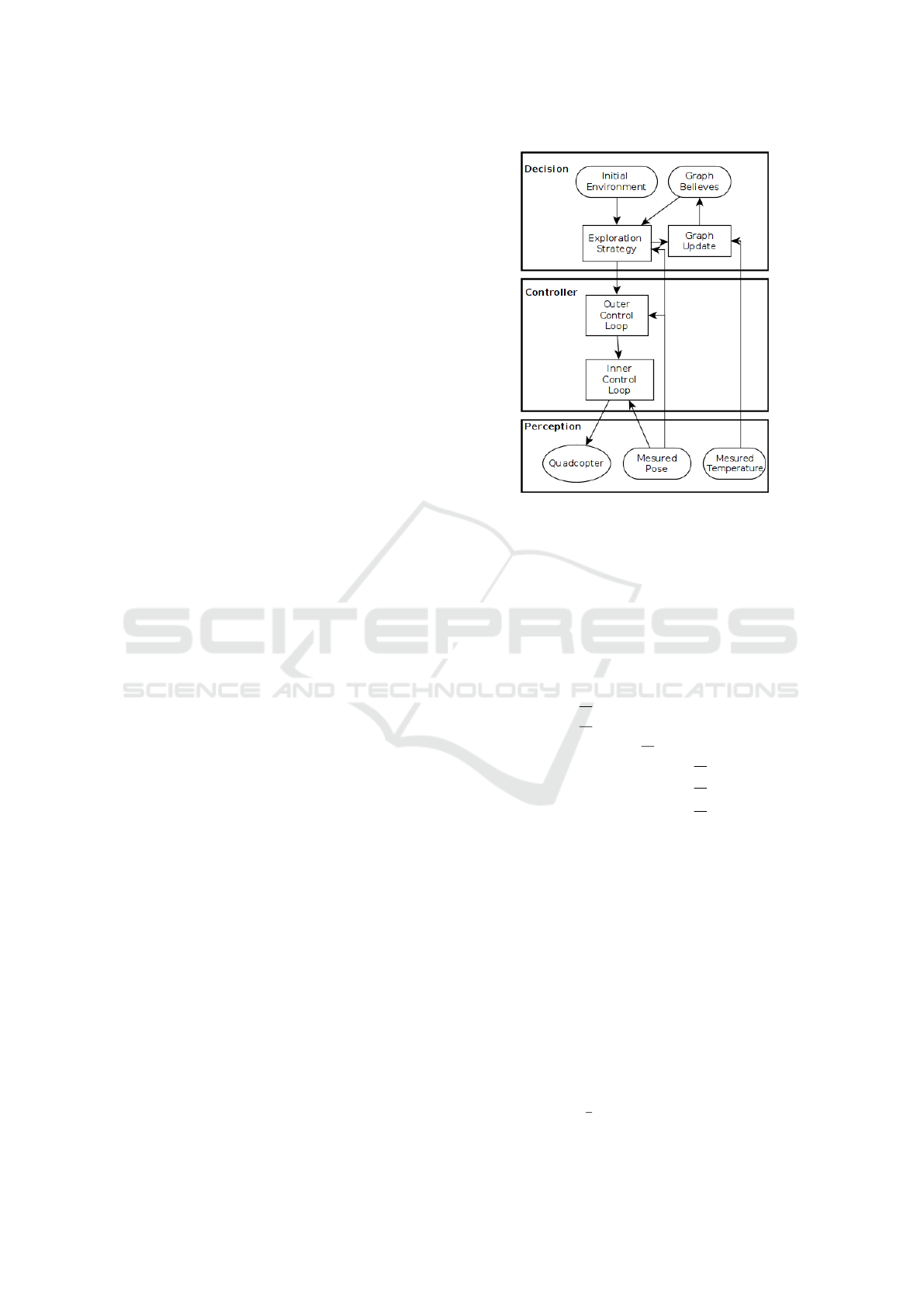
We developed a hierarchical architecture for an au-
tonomous UAV. We used for this architecture an ex-
ample of a developed quardrotor. The architecture is
represented in Figure 1. The three layers of the archi-
tecture are explained from down to up as follow:
• Perception. This layer contains exteroceptive
sensing, including temperature sensing for the ap-
plication at hand i.e. forest-fire localization, and
measurement of quadrotor pose. Several sensors
can be added in this layer for other kind of mis-
sion.
• Controller. The middle layer consists of outer
and inner control loops. Quadrotor pose infor-
mation from perception layer and is used by the
control layer to calculate and apply the desired
motion commands to the quadrotor. To do so,
Figure 1: Illustration of the embedded developed architec-
ture for the quadrotor.
we model the dynamic of our quadrotor. In or-
der to represents the quadrotor dynamic model,
let us consider ε = [x y z φ θ ψ ]
T
as the state of
the quadrotor in the fixed earth coordinate frame.
Taking into account Newton’s second law and Eu-
ler method (Benic et al., 2016), we approximate
the dynamical model of the quadrotor as follow:
¨x =
U
1
m
(cos(ψ)sin(θ)cos(φ) + sin(ψ)sin(φ))
¨y =
U
1
m
(sin(ψ)sin(θ)cos(φ) − cos(ψ)sin(φ))
¨z =
U
1
m
cos(θ)cos(φ) − g
¨
φ =
U
2
I
xx
¨
θ =
U
3
I
yy
¨
ψ =
U
4
I
zz
(1)
where
U
1
represents the total thrust,
U
2
, U
3
and U
4
represent the torque applied to x, y
and z axis respectively.
These forces are directly linked to the commands
U
i
:
U
1
=
∑
4
i=1
F
i
U
2
= l(F
2
− F
4
)
U
3
= l(F
1
− F
3
)
U
4
= c(F
1
− F
2
+ F
3
− F
4
)
(2)
with l the distance between each propeller and the
center of gravity of the quadrotor, b the thrust co-
efficient, c =
d
b
and d the drag coefficient.
Functional Architecture using ROS for Autonomous UAVs
507
F
i
represents the applied force to the rotor i. Con-
sidering a quadrotor, i ∈ [1, 2, 3, 4]. This force is
proportional to ω
2
i
(the square of the angular ve-
locity of the rotor i) and is computed as follow:
F
i
= bω
2
i
where b represents the thrust coefficient.
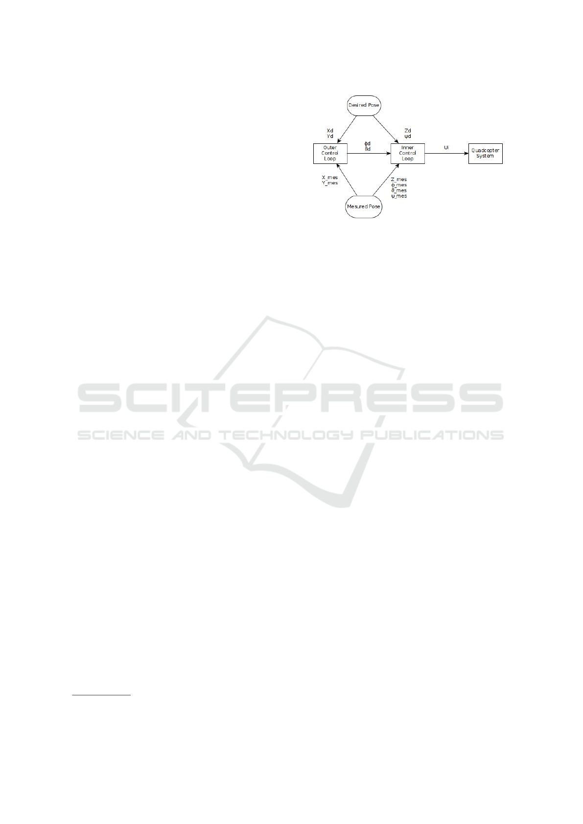
We then, compute the control law. Kotarski et
al. (Kotarski et al., 2016) explain the control law
the authors applied to their drone. As shown in
figure 2, the controller is divided in three parts:
first, the outer loop, which retrieves the desired
pose (x
d
, y
d
, z
d
, ψ
d
) from a task and the current
state of the drone (x, y, z, φ, θ, ψ) from sensors and
returns the desired roll and pitch angles φ
d
and θ
d
respectively.
Once you determine these desired angles, you
proceed to the inner control loop. This loop con-
sists of applying a PID controller, as explained by
(Kotarski et al., 2016). Here are the 4 commands:
U
1
= K p
z
e
z
+ Ki
z
R
e
z
+ Kd
z
˙e
z
+ mg
U
2
= K p
φ
e
φ
+ Ki
φ
R
e
φ
+ Kd
φ
˙e
φ
U
3
= K p
θ
e
θ
+ Ki
θ
R
e
θ
+ Kd
θ
˙e
θ
U
4
= K p
ψ
e
ψ
+ Ki
ψ
R
e
ψ
+ Kd
ψ
˙e
ψ
(3)
with e
i
= i
des
− i
mes
, i ∈ {z, φ, θ, ψ}.
• Decision. The top layer is decision layer, which
is responsible for the exploration strategy (Bel-
bachir et al., 2015). Temperature measurements
from the perception layer are fed directly as an
input to the decision layer. Taking into account
the belief graph, the initial environment and the
temperature measurements, the decision layer
decides the next moves to explore and sends them
to the middle i.e. control layer, where they are
converted to lower-level motion commands and
sent to the quadrotor actuators.
3 IMPLEMENTED SCENARIO
In this section, we explain the integration of our de-
veloped functional architecture (See section 2) in the
Robot Operating System (ROS
2
).
2
https://www.ros.org
Figure 2: Illustration of the Quadrotor control diagram. The
outer loop defines the desired roll and pitch angles sent as
inputs to the inner loop in order to compute the commands
sent to the quadrotor motors.
3.1 Robot Operating System
Robot Operating System (ROS) is an open source en-
vironment that allows us to create complex and ro-
bust robot behaviour using a set of libraries and tools.
Thus, a main program can be divided in several sub-
processes that will run in parallel and communicate
together.
Nodes. Nodes represent processes. Each of them
has a specific task in order to improve the efficiency
of the overall system. The communication between
these nodes is performed using a set of topics and ser-
vices.
Topics and Services. Topics are bridges over which
information, called messages, are sent from a node
into another. The nodes publish and/or subscribe
to topics in order to respectively sent and/or receive
these messages. A topic can only receive messages
whose type is specified by the user. For example a
node that publishes strings cannot publish integers on
the same topic.
Services are based on the request/response model: a
node provides a service that will be called by another
node using the service name. The node that created
the service is called the server, and the nodes that call
the service are called the clients. When the server
receives requests from a client, it analyzes them and
computes a specific task in order to send a response
to the client.
Topics should be used for continuous data streams,
whereas services are blocking calls and thus should
be used for remote procedure calls that terminate
quickly.
Figure 3 illustrates how nodes can communicate
together using either a topic or a service. On the top,
node
1
publishes a message that contains n parameters
ICINCO 2020 - 17th International Conference on Informatics in Control, Automation and Robotics
508
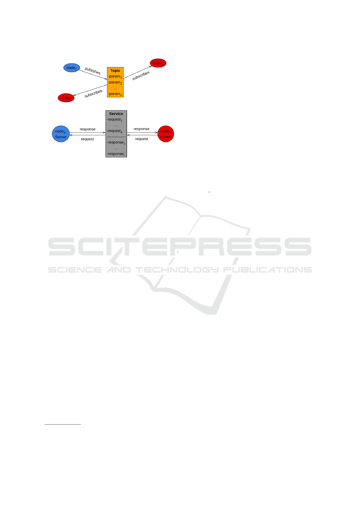
Figure 3: Topic and Service process: Nodes (executables)
are represented by ellipses. The communication between
nodes is represented by publishing/subscribing to topics or
by calling services.
on a topic. In the meanwhile, node
2
and node
3
sub-
scribe to this topic. On the bottom, node
5
is the client
and calls a service run by node
5
. The client sends a
request containing k parameters. Once the server re-
ceives the request, it computes the adequate function
and returns a response containing l parameters. This
response is then received by the client.
3.2 Gazebo
Gazebo
3
is a simulator offers the possibility to design
robots into indoor/outdoor environments that can be
either downloaded from database repositories or de-
signed by the users. Gazebo can generate sensors data
like sonar, laser rangefinder or camera, and noise can
be added to each sensor. Plus, physical forces can be
added like wind, especially for areal vehicles. Thus,
the robot is in conditions closed to reality, in order to
test the robustness of the developed programs.
Figure 4 represents the developed environment and
the model of our quadcopter.
3.3 ArduPilot
The developed controller was not implemented on
ROS. We decided to use a reliable existing solution
provided by ArduPilot
4
, an open source autopilot
system that provides controllers for a wide scale of
vehicles like drones, submarine and terrestrial vehi-
cles, aircraft, boats and helicopters.
Their controller is well suited for controlling UAVs
in any kind of environment (indoor/outdoor). A large
3
http://gazebosim.org
4
https://ardupilot.org/
number of Multi-UAV systems are based on this con-
troller (R. Braga, 2017) (Sardinha et al., 2018). More-
over, their controller exactly implements the one we
detailed in the previous section. In order to use
ArduPilot (e.g. takeoff), specific commands need to
be sent to ArduPilot. One will be to arm the motors
and the other one will be to takeoff the drone. The
same applies if the user wishes to land the UAV.
ArduPilot provides the UAV with several flight
modes. The main modes are described as follow:
• STABILIZED
The UAV is completely controlled by a user,
which means continuous commands must be sent
to the controller to get the UAV flying. Otherwise,
it will stay on the ground or worse, crash. Thus,
this mode is mainly chose if the user wants to
manually control the UAV.
• ALT HOLD
This is a low level autonomous mode: it en-
sures the UAV holds its altitude. However,
forward/backward and left/right motions can
occur.
• LOITER
Likewise, the UAV holds its altitude but also
its position. For instance, if the UAV needs to
maintain its position while performing image pro-
cessing using the data coming from an embedded
camera, this mode can be an option.
• AUTO
The UAV reaches a predefined set of way points.
For instance, this mode can be activated when the
task is related to a monitoring.
• GUIDED
The UAV autonomously navigates from its cur-
rent position to a received desired pose (position +
orientation). By defining an exploration strategy,
the next position the UAV should reach can be
sent at each iteration.
• LAND
The UAV reduces its altitude until it reaches
the ground, vertically. Then, the motors are
automatically disarmed.
For our architecture, we used the GUIDED mode
where the commands are sent by our decision layer.
All the commands listed above are sent to the con-
troller through a communication protocol called Mi-
cro Areal Vehicle Link (MAVLink) (Lamping et al.,
Functional Architecture using ROS for Autonomous UAVs
509
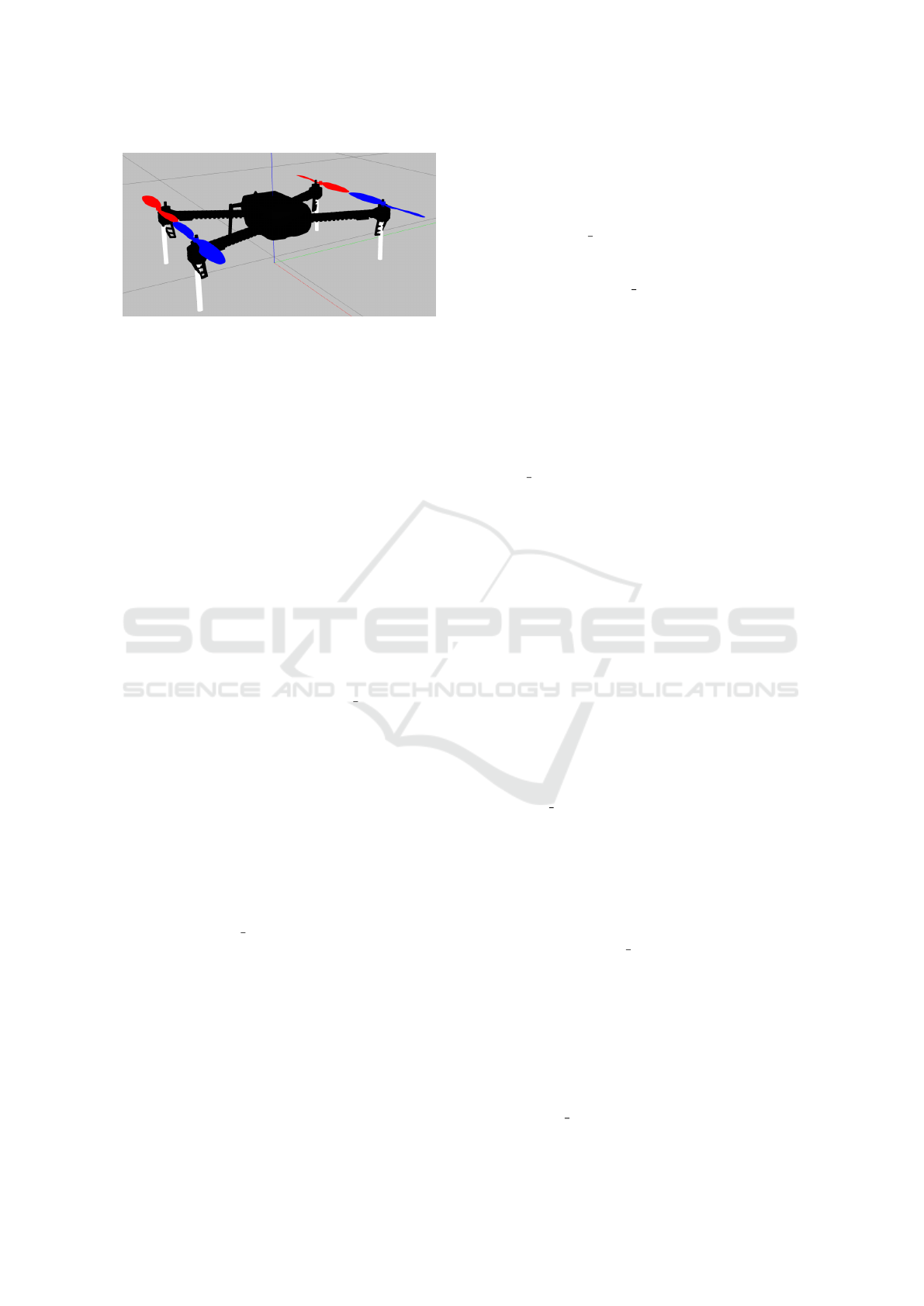
Figure 4: Model of the integrated quadrotor using Gazebo.
2018). Therefore, we used this protocol to setup the
communication between our nodes and this controller.
3.4 Integration of the Architecture in
ROS
The Nodes
We decided to test our architecture in a simulated
environment. We were working with a quadcopter
model integrated in Gazebo.
The way ROS is organized has resulted in the division
of our system in four nodes as follow:
1. Strategy. It illustrates the behaviour of the mod-
ule Exploration Strategy introduced in Figure 1.
Strategy retrieves the current position and orien-
tation of the quadcopter in its simulated environ-
ment [x
mes
, y
mes
, z
mes
, φ
mes
, θ
mes
, ψ
mes
]
t
, by sub-
scribing to the topic /mavros/local position/pose.
This pose is expressed with respect to the simula-
tor reference frame.
If the quadcopter has on-board sensors, it can
then analyse the environment in which it operates
and act accordingly. The data emanating from
the sensors are retrieved by subscribing to topics
generated by the simulator.
Depending on the strategy implemented, this
node determines the configuration [x
d
, y
d
, z
d
, ψ
d
]
t
that the quadcopter should have, as ex-
plained in section 2. Then, it publishes the
desired pose for the controller to the topic
/mavros/setpoint
position/local.
As explained in section 3.3, the controller needs
to receive commands to get the quadcopter off
the ground, operate and then land. Thus, Strategy
calls the service /mavros/cmd/arming to arm the
motors, /mavros/cmd/takeoff to get the UAV off
the ground and /mavros/cmd/land to land it.
2. mavros. It is a bridge between ROS and the con-
troller. This node uses MAVLink to setup the
communication between the nodes executed on
ROS and the controller of the quadcopter, as ex-
plained in section 3.3.
mavros subscribes to the topic
/mavros/local position/pose to get the de-
sired pose of the quadcopter. It publishes
the current pose of the quadcopter to the
topic /mavros/local position/pose as well as
the information about its battery, to the topic
/mavros/battery.
Plus, it also works as a server and waits for
a client to send a request on several services:
/mavros/cmd/arming, /mavros/cmd/takeoff and
/mavros/cmd/land. These services are called by
Strategy as discussed before.
3. sim vehicle.py. This software in the loop runs the
controller developed by ArduPilot, in a simulated
environment. It receives MAVLink messages
from mavros and computes the sent commands
for the quadcopter’s motors.
These commands can be: arming the motors,
taking off, landing, going from the quadcopter’s
current pose to a desired one or getting the
quadcopter to reach a set of way-points.
Most of the received commands by the controller
depend on the embedded strategy. Each command
sent to the motors is contained in a MAVLink
message and then interpreted in Gazebo. Like-
wise, the controller receives MAVLink messages
from the simulator to get the pose of the quad-
copter.
4. gazebo ros. This node runs Gazebo simulator,
in which our quadcopter operates in our en-
vironment. As stated above, Gazebo receives
MAVLink commands from the controller to
move the quadcopter accordingly. Plus, it sends
the robot’s pose and its battery status to the
controller.
Depending on the embedded sensors on the
quadcopter, gazebo ros will publish sensor data
on different topics.
Figure 5 illustrates how our hierarchical architec-
ture is represented by processes, running either on
ROS, or linked to ROS such as the controller.
The decision layer (see Figure 1) is repre-
sented by Strategy (see Figure 5), which com-
municates with mavros through the topics
/mavros/local position/pose, /mavros/battery and
ICINCO 2020 - 17th International Conference on Informatics in Control, Automation and Robotics
510
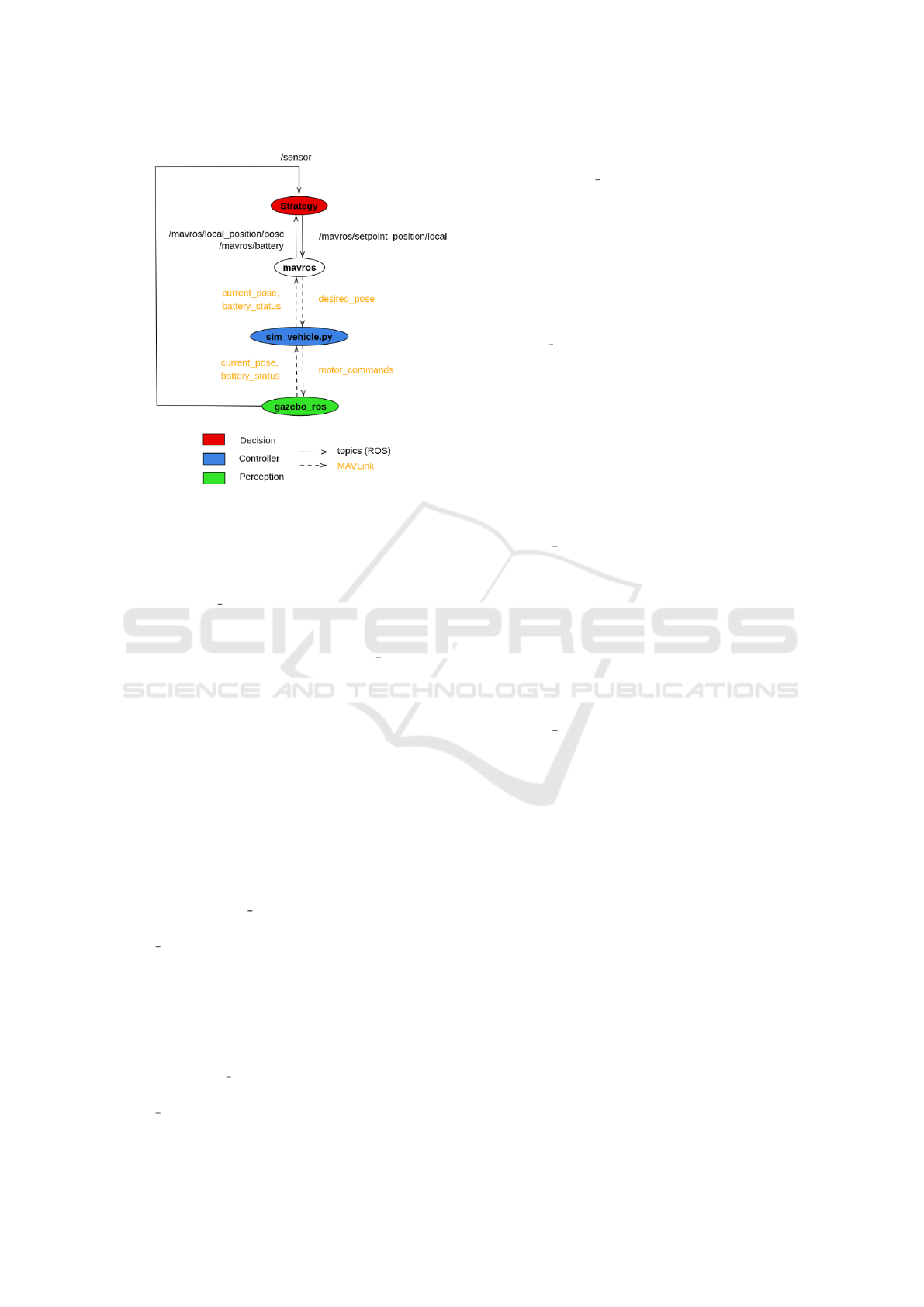
Figure 5: Communication graph of the implemented nodes
on ROS. Decision, controller and perception layer are a set
of executables running either on ROS or linked to ROS. Two
types of communication is represented: topics, when the
nodes are in ROS and MAVLink for the external controller.
/mavros/setpoint position/local. Plus, data coming
from a simulated sensor in gazebo are retrieved by
the decision layer on the topic /sensor.
The controller layer is represented by sim vehicle.py
which communicates with mavros and gazebo
through MAVLink messages. MAVLink communica-
tions are represented by dashed arrows whereas ROS
communications are modeled by continuous arrows.
Finally, the perception layer is symbolised by
gazebo ros.
The Topics
As discussed previously, only one type of message
can be published on a topic. Thus, the topics and the
related messages we used for the communication be-
tween the nodes are described as follow:
• /mavros/setpoint position/local. This
topic receives messages of type geome-
try msgs/PoseStamped whose parameters are
coordinates [x, y, z] in meters and an orientation
expressed in quaternion. Plus, the time at which
the message was sent as well as the reference
frame in which the pose is expressed are specified
by the node that publishes the message.
• /mavros/local position/pose. Likewise, this
topic receives messages of type geome-
try msgs/PoseStamped.
• /mavros/battery. This topic receives messages
of type mavros msgs/BatteryStatus whose param-
eters are battery’s voltage (V), battery’s current
(A) and the remaining battery level (%).
The Services
The following services are carried out by mavros
(server).
• /mavros/cmd/arming. The client uses a
mavros msgs/CommandBool message type: as
a request, the client needs to indicate by true or
false the desired state of the motors. Either they
will be armed (true) or disarmed (false).
The server will return to the client a boolean that
represents whether or not the request was treated
and an integer which defines if the request was
successfully executed: 0 if it is a success and 4
otherwise.
• /mavros/cmd/takeoff. The client uses a
/mavros msgs/CommandTOL message type: as
a request, the client needs to specify the desired
altitude for the quadcopter after taking off and
can optionally define the desired coordinates (lat-
itude, longitude, yaw). In fact, if the coordinates
are not specified (all the values are equal to 0),
the quadcopter will simply takeoff vertically and
stabilize at the desired altitude.
• /mavros/cmd/land. Similarly, the client uses a
/mavros msgs/CommandTOL message type: the
user can attribute 0 to all the requested parameters
so that the quadcopter will land vertically. Other-
wise, it can specify a desired coordinate for the
landing. The altitude parameter defined in the re-
quest by the client will not be considered by the
server, as the quadcopter lands.
4 CONCLUSION AND FUTURE
WORKS
In this article, we defined a functional architecture in
order to control a drone to explore its environment.
This architecture is divided into three layers: deci-
sion, control and perception. This architecture was
implemented using Robot Operating system in order
to prove the feasibility. Several nodes and topics were
defined and our drone was able to explore its environ-
ment (see the following link: https://www.youtube.
com/watch?v=8ySzFayPYh4&feature=youtu.be).
Functional Architecture using ROS for Autonomous UAVs
511

In order to expand the functional architecture, we
are planning to embed several sensors such as ther-
mal camera. Additionally, the adequate communica-
tion device will be implemented in order to accom-
plish cooperative missions.
REFERENCES
Alami, R., Chatila, R., Fleury, S., Ghallab, M., and Ingrand,
F. (1998). An architecture for autonomy. The Interna-
tional Journal of Robotics Research, 17.
Asmaa, I., Boukhdir, K., and Hicham, M. (2019). Uav con-
trol architecture: Review. International Journal of Ad-
vanced Computer Science and Applications, 10.
Belbachir, A. and Escareno, J. (2016). Autonomous de-
cisional high-level planning for uavs-based forest-fire
localization. In Proceedings of the 13th International
Conference on Informatics in Control, Automation
and Robotics - Volume 1: ICINCO,, pages 153–159.
INSTICC, SciTePress.
Belbachir, A., Escareno, J., Rubio, E., and Sossa, H. (2015).
Preliminary results on uav-based forest fire localiza-
tion based on decisional navigation. pages 377–382.
Benic, Z., Piljek, P., and Kotarski, D. (2016). Mathemat-
ical modelling of unmanned aerial vehicles with four
rotors. Interdisciplinary Description of Complex Sys-
tems, pages 88–100.
Brooks, R. (1986). A robust layered control system for a
mobile robot. IEEE Journal on Robotics and Automa-
tion, 2(1):14–23.
Janssen, R., van Meijl, E., Di Marco, D., van de Molengraft,
R., and Steinbuch, M. (2013). Integrating planning
and execution for ros enabled service robots using hi-
erarchical action representations. In 2013 16th Inter-
national Conference on Advanced Robotics (ICAR),
pages 1–7.
Kotarski, D., Benic, Z., and Krznar, M. (2016). Con-
trol design for unmanned aerial vehicles with four ro-
tors. Interdisciplinary Description of Complex Sys-
tems, pages 236–245.
Lamping, A., Ouwerkerk, J., Stockton, N., Cohen, K., and
Kumar, M. (2018). Flymaster: Multi-uav control and
supervision with ros. In AIAA Aviation Forum.
Li, M., Yi, X., Wang, Y., Cai, Z., and Zhang, Y. (2016).
Subsumption model implemented on ros for mobile
robots. In 2016 Annual IEEE Systems Conference
(SysCon), pages 1–6.
Maciel-Pearson, B. G., Marchegiani, L., Akcay, S.,
Abarghouei, A. A., Garforth, J., and Breckon, T. P.
(2019). Online deep reinforcement learning for au-
tonomous UAV navigation and exploration of outdoor
environments. CoRR, abs/1912.05684.
Mcgann, C., Py, F., Rajan, K., Thomas, H., Henthorn, R.,
and McEwen, R. (2008). A deliberative architecture
for auv control. pages 1049 – 1054.
Misra, S., Mukherjee, A., Rahman, A. U., and Raghuwan-
shi, N. S. (2020). ROSE: random opportunistic and
selective exploration for cooperative edge swarm of
uavs. In 2020 International Conference on COMmuni-
cation Systems & NETworkS, COMSNETS 2020, Ben-
galuru, India, January 7-11, 2020, pages 368–374.
IEEE.
R. Braga, R. Silva, A. R. F. C. (2017). A combined approach
for 3d formation control in a multi-uav system using
ros. In International Micro Air Vehicle Conference
and Flight Competition.
Sardinha, H., Dragone, M., and Vargas, P. (2018). Closing
the gap in swarm robotics simulations: An extended
ardupilot/gazebo plugin.
Wang, S., Liu, L., Qu, L., Yu, C., Sun, Y., Gao, F., and
Dong, J. (2019). Accurate ulva prolifera regions
extraction of UAV images with superpixel and cnns
for ocean environment monitoring. Neurocomputing,
348:158–168.
Yi, X., Wang, Y., Cai, Z., and Zhang, Y. (2016). Subsump-
tion model implemented on ros for mobile robots.
pages 1–6.
ICINCO 2020 - 17th International Conference on Informatics in Control, Automation and Robotics
512
