
Failsafe Mechanism to Hazard Analysis and Risk Mitigation in
Unmanned Aerial Vehicle based on NCES
Mohamed Naija, Rihab Khemiri and Ernesto Exposito
Univ. Pau & Pays Adour, E2S UPPA, LIUPPA, Anglet, France
Keywords: Unmanned Aerial Vehicles (UAVs), Reconfiguration, NCES, Safety, Model Checking.
Abstract: In the last few years, Unmanned Aerial Vehicles (UAVs) are receiving more focus in order to execute a wide
variety of applications such as the military, agriculture and medical fields. It is known the high vulnerability
of the UAV not only to unexpected faults of their software but also to the environment. For this reason, safety
should be considered as the main requirement at design time, since any unexpected behavior of the vehicle or
any hazard would lead to potential risks. To maintain their safe operation during their missions, a failsafe
mechanism based on Net Condition Event System (NCES) is proposed. The failsafe mechanism is a control
logic that guides risk reduction actions to be performed when hazards occur. To generate such a controller
using formal models, the proposed process is decomposed into three phases: (1) the first phase consists on
hazard identification and analysis according to reactive methods of literature, (2) the second phase allows risk
estimation using the standard ISO 13849, and (3) the third phase consists of performing reconfiguration
scenario in order to risk mitigation while analyzing safety requirements. The motivation behind the use of
formal methods is that they have proven to be useful for making the development process reliable at early
design stages. We demonstrate the applicability and feasibility of our proposal on an illustrative medical drone
as a case study.
1 INTRODUCTION
Air Transportation System has become the most
important sectors in the global transportation system.
Unmanned Aerial Vehicles (UAVs), aka drones, have
been encountered a significant focus to be used in
transportation purposes in smart cities in order to
reduce costs and increase delivery efficiency. The
popularity of Unmanned Aerial Vehicles is confirmed
by the Federal Aviation Administration, which
expects that the number of drone’s users will increase
from 1.1 million in 2016 to 3.55 million in 2021
(Atkinson, 2018). The UAVs are considered high-
assurance since errors during execution could result
in great damage, injury, and loss of life (Zhang et al.,
2009). We emphasize that more than 4,889 incidents
have been reported between 2014 and 2017.
Therefore, a stronger form of verification is likely to
be needed to ensure the correctness of the system and
provide sufficient evidence for safety certification.
Safety can be defined as a “state in which the
system is not in danger or at risk, free of injuries or
losses” (Sanz et al., 2015). Because nothing is totally
safe and there is no situation where no risk can occur,
safety is also defined as the absence of unacceptable
risks (Allouch et al., 2019). Since UAVs are highly
interconnected and prone to external disruptions, the
vehicle must be able to detect and evaluate hazards
along with their consequences in order to apply the
necessary measures for reducing the risk to an
acceptable level and ensuring resilience.
Consequently, a failsafe mechanism that controls all
the components of the system and ensuring safe
operations despite the presence of faults is needed.
At present, the failsafe mechanism design for
drones is seldom investigated (Dong et al., 2019). In
this paper, we propose a new failsafe mechanism
allowing safety assessment for UAVs at an early
design stage. Our proposal consists of hazard
identification and analysis. Based on this analysis, we
estimated the required Performance Level (PLr)
needed to manage the failure in a safe way. For this
purpose, we use the risk graph of Standard ISO
13849. Finally, the controller makes a decision on the
recovery mode to perform. So, we apply
reconfiguration-based risk reduction. The
reconfiguration scenarios consist of switching from
an initial mode to a recovery mode and modify the
220
Naija, M., Khemiri, R. and Exposito, E.
Failsafe Mechanism to Hazard Analysis and Risk Mitigation in Unmanned Aerial Vehicle based on NCES.
DOI: 10.5220/0009887802200227
In Proceedings of the 15th International Conference on Software Technologies (ICSOFT 2020), pages 220-227
ISBN: 978-989-758-443-5
Copyright
c
2020 by SCITEPRESS – Science and Technology Publications, Lda. All rights reserved

software configuration to ensure resilience, using
formal models.
Model-checking offers an attractive approach to
automatically analyzing models for adherence to
safety properties (such as efficiency, reliability,
robustness, stability, and vivacity). In particular, we
use the Net Condition Event System (NCES) (Rausch
and Hanisch, 1995) formalism, which is modular with
extra condition/event signals and can be verified
using the model checking (Li et al., 2013) and the
model checker SESA (Vyatkin, 2007). Moreover, the
hierarchical composition of the NCES component
allows reducing the size and complexity of the nets
(Vyatkin, 2007) (Li et al., 2013).
Compared with current failsafe mechanisms, our
approach has three main advantages which are correct
by design, compact and modular. This has been well
presented in the application of a medical drone crash
scenario.
The rest of this paper is organized as follows. We
propose a background of the NCES formalism in
Section II, in section III, related work to drone’s
safety is discussed. After introducing the UAV model
in Section IV, Section V presents our failsafe
mechanism based on three phases, Section VI shows
that our approach can be effectively applied to a case
study. Section VII concludes the paper and sketches
some future work.
2 BACKGROUND
This section presents the basics of the Net Condition
Event Systems (NCES) formalism, which will be
useful for describing our proposal.
Net Condition/Event Systems is an extension
class of Petri nets. It consists of modules whose
dynamic behavior is modeled by means of Petri nets.
This formal concept was introduced in (Rausch and
Hanisch, 1995) according to which a hierarchical
NCES component is a Place-Transition Net described
by the following tuple:
N
CES = {P, T, F, M
O
, , CN, EN}
(1)
where:
P : is an ordered set of n places p;
T : is an ordered set of m transitions t;
F : is the incidence matrix;
M
O
: is the initial marking;
: is the input/output structure;
CN ⊆ (P × T) is a set of condition signals;
EN:⊆(T×T) is a set of event signals.
The semantics of NCES are defined by the firing
rules of transitions (Khalgui, 2010). There are several
conditions to be respected to enable a transition to
fire. First, as it is in ordinary Petri nets, an enabled
transition has to have a token concession. That means
that all pre-places have to be marked with at least one
token. Furthermore, a transition in NCES may have
incoming condition arcs from places and event arcs
from other transitions. A transition is enabled by
condition signals if all source places of the condition
signals are marked by at least one token. The other
type of influence on the firing can be described by
event signals which come to the transition from some
other transitions. Transitions are spontaneous if there
are no incoming event arcs to the transition, otherwise
they are considered as forced. A forced transition is
enabled if it has token concession and it is enabled by
condition and event signals.
In regards to the formal verification engine, the
model checker SESA (Vyatkin, 2007) allows an
automatic validation of NCES models of components
by checking functional and non-functional
requirements. So, SESA allows performing analysis
of typical properties such as (i) the liveness of
transitions, (ii) boundedness of places of the net, and
(iii) the reachability graph of the net. Other safety
property can be specified using the computation tree
logic (CTL) (Clarke et al., 1986) and verified by the
model checker SESA.
3 RELATED WORK
Due to the current lack of international standards,
tools, and guidelines that govern the design and safety
certification of drones, many approaches have been
proposed in the literature for safety assessment and
fault tolerance in UAVs from high-level models.
In (Mhenni et al., 2016), authors have benefited
from UAV case study to design a framework called
SafeSysE, which allows the automatic generation of
safety artefacts. They combine Model-Based Systems
Engineering (MBSE) and Model-Based Safety
Analysis (MBSA) to provide safety assessment by
integrating Failure Mode (FM), Effects Analysis
(EA) and Fault Tree Analysis (FTA) for safety
checking. Nevertheless, this process is not fully
prototyped and has not been tested in real scenarios.
In the same vein, (Sankararaman, 2017) have
presented a framework for identifying and predicting
the occurrence of a simple case of hazards (i.e. battery
discharging and collision) that can affect drones at
runtime. Unlike this approach, our contribution
Failsafe Mechanism to Hazard Analysis and Risk Mitigation in Unmanned Aerial Vehicle based on NCES
221

studies various risk factors and hazards that affect the
dynamic operation of drones.
In (Neff and Garman, 2016), the authors turn on
the identification of errors and hazards in Unmanned
Aerial Vehicles related to human factors, which are
inevitable mistakes. In addition, the proposed
mitigation techniques cannot be applied to software.
Other efforts have been specifically based on
using ISO standards for safety analysis. Sanz et al.
(Sanz et al., 2015) present an iterative approach
including identification, assessment and reduction
procedures to find sources of hazards when using
UAVs in performing agricultural missions.
Unfortunately, the paper does not provide a full
description of the validation test, which is an ad-hoc
test.
In (Allouch et al., 2019), the authors propose a
functional safety methodology for Unmanned Aerial
Vehicles operations by using both ISO 13849 and
ISO 12100 standards. The paper present two-
approach for qualitative and quantitative risk analysis
and safety assessment. The proposed methodology
starts with hazard identification and risk assessment
to safety analysis with probabilistic modeling without
proposing solutions for fault tolerance.
In (Dong et al., 2019) a failsafe mechanism design
for autonomous aerial refueling is devoted. The
authors use the State Tree Structures (STS) to risk
analysis and mitigation at design time. A supervisor
is synthesized to cover common system failures and
interaction among receivers, tankers and pilots. The
design procedures presented in this work deals only
with command conflicts that lead to dangerous
maneuvers.
4 UAV MODEL
In what follows, we present the architecture of the
UAV system, we explain the flight modes and we
state the UAV system limits.
4.1 System Architecture
The drone system is decomposed into three modules
that are responsible of running specific tasks and
algorithms with respect to hardware and timing
constraints. Each module unit can repeat a variety of
algorithms in a constant frequency for performing
their task, as detailed below:
Localization Unit: The UAV is able to
localize its operating environment and itself
accurately using sensory input (such as a
monocular camera, IMU, and GPS).
Localization information is then transferred to
the Perception unit.
Perception Unit: Received data are used by
the obstacle detection algorithm to build the
Vision-based Navigation Guidance. Based on
this navigation model, a guidance algorithm is
executed to determine the flight path. Finally,
accurate commands are sent to the motion
control system of the drone.
Control Unit: On this level, reference data for
the flight stability and waypoint tracking
manoeuvres are computed and converted to
applicable variables.
4.2 Flight Modes
The communication between the ground control
station and the unmanned aerial systems is necessary
to ensure the functioning of the system. They
typically communicate through a wireless connection
and exchange a set of messages using the Micro Air
Vehicle Link (MAVLink) protocol (Koubâa et al.,
2019). To ensure the safety of the drones, it is crucial
to study flight modes that were supported by the
MAVLink protocol:
The STABILIZE Mode: This mode allows
controlling the drone manually through the
RC controller. When the autopilot becomes
unable to control the vehicle system in any
other mode, it is highly recommended to
switch to this mode.
ALTITUDE HOLD: this mode is considered
the most comfortable one to control the
vehicle. In this mode, the user does not have
to take care of maintaining a fixed altitude for
the unmanned system, since the autopilot will
be in charge of controlling the altitude
automatically. The user will be responsible
for manually controlling the position of the
unmanned system and the direction. In this
mode, we do not need a GPS, since the
altitude is estimated using the barometer. It
has to be noted that this mode is more suitable
for beginners than the STABILIZE mode.
LOITER: The LOITER mode is very similar
to the STABILIZE mode, but it will have to
take care of maintaining orientation, altitude
and current location of the unmanned system
if the user does not make inputs to the RC
controller. To maintain the position, this mode
needs a GPS 3D or optical flow. In this mode,
high performance is related to some factors
ICSOFT 2020 - 15th International Conference on Software Technologies
222
(i.e. low vibration, low magnetic interference
of the compass and GPS Lock).
LAND: This mode allows the unmanned
aerial system to land to the ground.
RTL (Return-To-Launch): This mode
strength the drone to return to the home
position and land to the ground. It has to be
noted that the LAND and RTL mode are
adapted in the case of geofence and violation
of navigation safety.
GUIDE: In this mode, the drone is guided to
autonomously navigate to a specific location
chosen by the user and defined by the GPS
coordinates. The GUIDED mode only works
with GPS mode. Indeed, when the GPS
performs a 3D fix and is activated, the drone
may be sent to navigate autonomously to a
specific ground station defined by the GPS
coordinates. In this context, a ground station
is usually exploited to send navigation
waypoints to the unmanned aerial systems to
autonomously navigate to it.
AUTO: it's the autonomous mode where the
drone will follow a preprogrammed mission,
consisting of a set of waypoints. If the AUTO
mode is activated, the drone will
autonomously navigate to each waypoint.
4.3 System Limits
This subsection summarizes the limits of the drone
system so as to evaluate their possible consequence
later. They are the list of failures that should be taken
into the inherent activities in the design phase of a
UAV system. According to (Sanz et al., 2015), the
drone's limits are divided into four categories
depending on their nature. The description of each
category is shown in Table 1 through concrete
examples.
Table 1: The limits of UAV according to their nature.
Nature Description
Physical
Maximum payload, maximum
kinetic energy and maximum spee
d
Temporal
Maximum time of flight, response
time, engines life time and battery
degradation
Behavioral
Minimum distance to the operator,
sensing capacities of the vehicle and
procedures of piloting
Environmental
Weather conditions, minimum
distance from populated areas, GPS
coverage and communication
degradation.
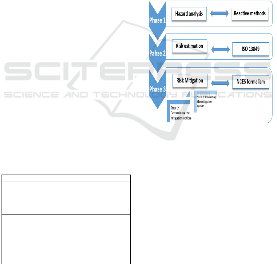
5 RECONFIGURABLE FAILSAFE
MECHANISM
In this paper, we address the problem of safety in
Unmanned Aerial Vehicles based on reconfiguration
as a recovery technique. The proposed failsafe
mechanism (refer to Figure 1) is divided into three-
step allowing the analysis of safety requirements at an
early design stage. Since the first step consists of
detection and analysis of hazards according to their
sources, the second step implies estimating the
performance level required to risk reduction using the
international standard ISO 13849. Finally, the third
step include risk mitigation via a reconfiguration
scenario, which allows avoiding a potential
breakdown and accident during the drone's mission.
Figure 1: Overview of the proposed process.
We use the NCES formalism to represent three
types of modules (i) a Listener module that takes into
account the hazard analysis step, (ii) a Coordinator
module able to evaluate the risk and the inherent
decision-making process and (iii) Modes modules
representing the normal behavior together with the
potential failure behavior. Each module is achieved
by algorithms that sustain the functionalities of the
specified entity and interact with the hardware to
perform its role. Formally, each NCES component is
modeled with three transitions, which allows
receiving data from the sensory input, running a
specific algorithm corresponding to the received data
and activating the corresponding modules.
In what follows, we detail the three phases of the
proposed approach.
Failsafe Mechanism to Hazard Analysis and Risk Mitigation in Unmanned Aerial Vehicle based on NCES
223
5.1 Phase 1: Hazard Analysis
The first step of our proposal consists of hazard
identification and analysis. For this purpose, we
implement an NCES component, called Listener, that
oversees the system and detect errors at run-time.
When running the Listener module uses a list of
potential UAV errors according to their sources as a
checklist (see Table 2) during hazard identification.
This list is prepared from the US Federal Aviation
Authority (FAA), the NASA's Aviation Safety
Reporting System (ASRS) and the European Aviation
Safety Agency (EASA). Once identified the
candidate hazard, the Listener sends an event signal
to the control module that is responsible for the drone
mission achievement. In this paper, we assume that
only one fault can occur at the same time in the
system.
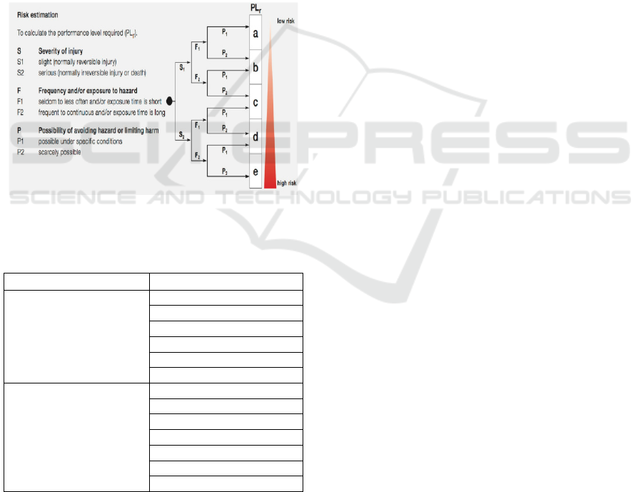
Figure 2: Risk Graph for Evaluation of the PLr according
to ISO 13849.
Table 2: List of Hazards.
Source Type
External
Environmental conditions
Radiation
Aerodynamics
Obstacles
Networking
Human element
Internal
Software erro
r
Hardware erro
r
Flight control
Mechanical
Power supply breakdowns
Electronic
Thermal
5.2 Phase 2: Risk Estimation
At this level, the risk must be estimated to specify the
ability of the UAV to achieve a recovery function
under predictable conditions. For this purpose, we
define an NCES component, called Coordinator,
which refers to the Standard ISO 13849 to determine
the required Performance Level (PLr).
In this sense, risk estimation is a function of three
factors: (1) severity of possible injury or the damage
to health (S), (2) frequency of exposure to hazard (F)
and (3) the possibility of avoiding the hazard (P).
These three parameters take into account both
quantity and quality aspects of each hazard:
Severity (S): This parameter is a key factor in
determining the seriousness of the hazard.
The severity rate is equal to S2 if the hazard
induces high injury or death. Otherwise, the
rate of severity is equal to S1.
Frequency (F): This parameter reflects the
exposition time of the UAV to the hazard. The
exposition value is evaluated as an F2 if the
UAV is continuously exposed to the hazard.
Else, the frequency value is estimated as an
F1.
Possibility (P): It is the ability to avoid/limit
the injury/harm when a hazardous situation
occurs. The probability of avoiding such
damage can be represented by P2 if there is no
chance of avoiding the hazard. Alternatively,
the probability value is P1.
The relation between the parameters described
above estimates the PLr to manage the hazard using a
risk graph. As depicted in Figure 2, the Performance
Level is classified at five grade ranging from the low
level 'a' to the higher-level 'e'.
5.3 Phase 3: Risk Mitigation
The Coordinator entity tries to manage the residual
risk and keep the system in a safe state. The
undertaken measures by this making-decision entity
are at the level of switching from an initial mode to a
recovery mode via a reconfiguration scenario. For
this, two steps are necessary.
5.3.1 Determining the Mitigation Option
The coordinator's role is to choose the target
configuration that keeps the system in a safe state.
However, the coordinator will decide on the operating
mode that can allow the autonomous vehicle's
mission to be achieved as much as possible or to stop
the mission, if necessary. This step is very delicate
because an inaccurate decision can lead to
catastrophic situations and injury. Based on the PLr
estimation, we define a decision graph guarantying a
ICSOFT 2020 - 15th International Conference on Software Technologies
224
sufficient safety level when hazards occurs, as shown
in Figure 3. It is important to note that the NCES
coordinator-module encapsulates the implemented
algorithm that supports the functionalities of the
decision graph when applying reconfiguration.
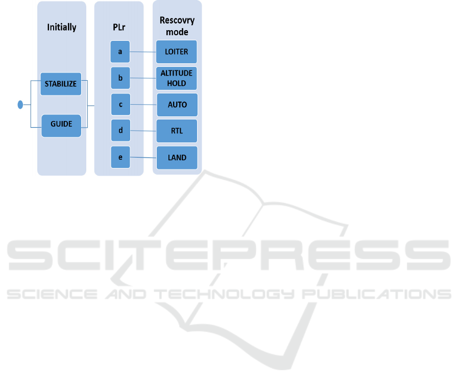
Figure 3: Decision Graph for risk mitigation.
Initially, the UAV can run either in manual mode
(i.g. Stabilize mode) or in AUTO mode, depending on
user preferences. When a failure is detected, and after
an estimate of the risk, the coordinator switches from
the initial mode to a recovery mode depending on the
the required PL for managing hazard. For example, if
the Plr is at level 'e', the decision made by the
coordinator is to stop the mission and nail the vehicle
to the ground by switching to LAND mode. If the PLr
is estimated at level 'a', the LOITER mode will be
selected that allows accomplishing the mission.
5.3.2 Evaluating the Mitigation Option
In this step of the process of risk reduction, we verify
that the decision of switching behavior does not lead
to an inconsistent state or cause any damage to the
system, i.e., safety requirement.
To this end, it is important to specify all possible
configurations that represent all modes of a system,
the Listener module and the Coordinator module.
Then, additional information describing the switching
modes and limiting changes must be specified using
event signals and condition arcs. The source and
target operating modes should not include
information about each other or about
reconfiguration.
As soon as the NCES systems model is available,
the safety requirement can be checked. As already
mentioned, the advantage of NCES-based models is
that offers an effective and optimal solution to make
the verification process easier with a low complexity
(Zhang et al., 2013) (Naija and Ahmed, 2016). The
safety of an UAV requires the correctness of each
configuration and also of the reconfiguration
scenarios. Thus, the verified properties are (i)
Liveness of the net by checking that all modes are
achievable, (ii) Deadlock cannot occur by verifying
boundedness of all places of the network and (iii)
Stability of the network, that can be proved with the
generation of the reachability graph with finite state
of the system. The reconfiguration is applied only if
these properties are well-checked.
6 CASE STUDY
To better explain our contribution, a medical drone
use case is used to validate the advantages and
effectiveness of our proposal, since the medical drone
service has become an emerging topic in a smart city.
The vehicle's services are revolutionizing the way
time-critical medical supplies are delivered to
patients who require immediate medical attention.
Medical drones are considered as a complex and
high-assurance system.
We consider the scenario of an UAV that goes
from pickup to drop-off in an urban city and fly at an
altitude of fewer than 150 meters through the GUIDE
mode. The control station is able to assign missions
to the UAV in real-time or modify the initial mission
by adding waypoints as required to reach victims
within minutes. In this work, the UAV has embedded
Wi-Fi and Bluetooth interfaces. We also assume that
the physical properties such as vehicle's speed and
safety distance varies according to the operating mode
and final user's requirements. The communication link
with the ground station is assured through a 4G
connection using the MAVLink protocol.
6.1 Phase 1: Hazard Analysis
The UAV starts the mission into the GUIDE mode,
which is characterized by a stable communication
with the ground station. During run-time, the Listener
module detects a packet loss due to communication
degradation (i.e. firing the transition source
t_entrance of the Listener module in Figure 4).
Therefore, to analyze this hazard an algorithm is
executed (i.e. firing the transition t_start). After
identifying the nature external of the hazard and the
type as a Network, an event signal is sent to the
Coordinator module. We emphasize that the only role
of the Listener is the continuous control of the system
for hazard detection and identification.
Failsafe Mechanism to Hazard Analysis and Risk Mitigation in Unmanned Aerial Vehicle based on NCES
225
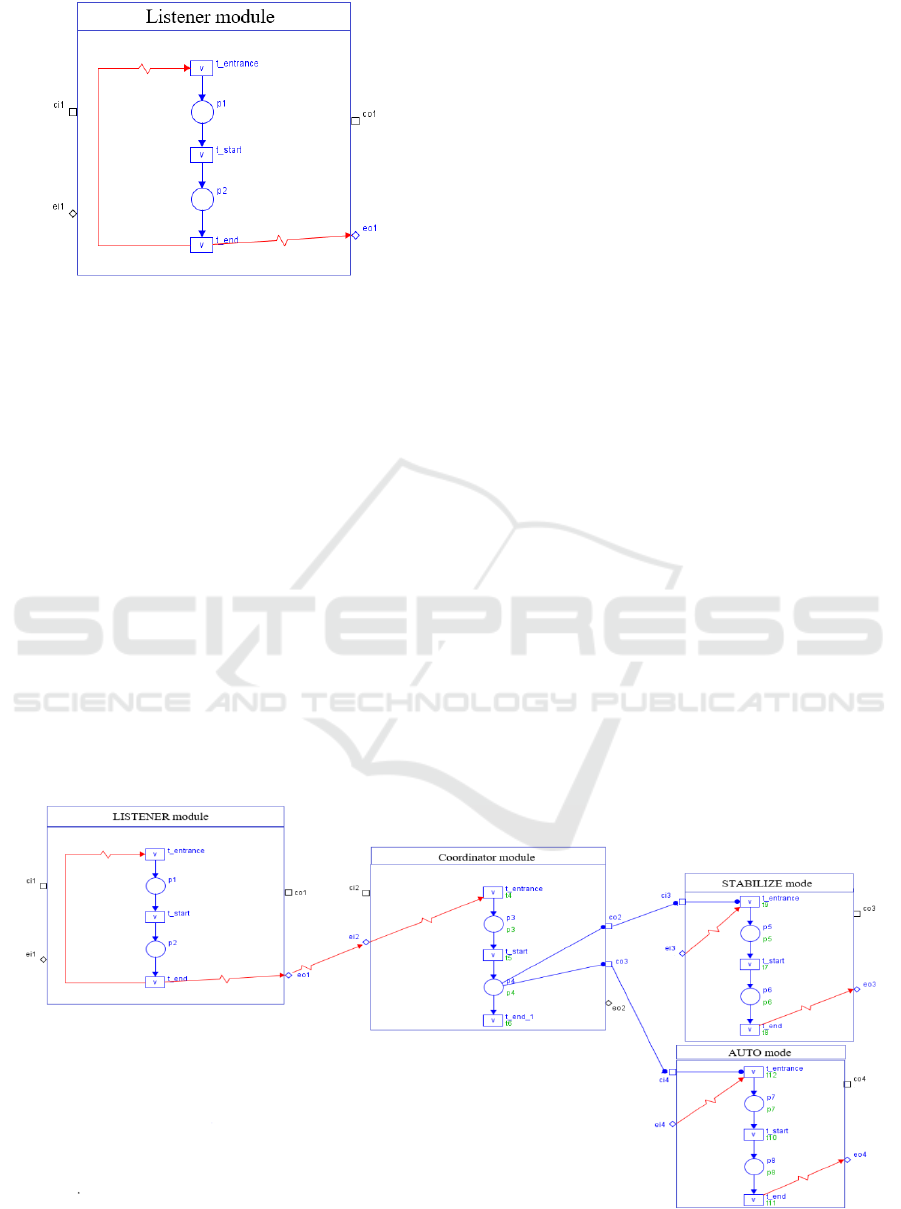
Figure 4: The Listener module.
6.2 Phase 2: Risk Estimation
Once the event signal is received, the Coordinator
module evaluates the Hazard in order to estimate the
required performance level based on the ISO 13849
risk graph. The communication degradation hazard
can lead to the interruption of the mission. So, the
severity (S) of the communication hazard is estimated
(S1). Generally, this type of breakdown is persistent
and leaves the vehicle exposed to risk for a long time
(F2). In addition, it is impossible to avoid this hazard
because it is due to a loss of signal or a connection
problem. So, the possibility of avoiding hazard (P)
corresponds to (P2). It is then easy to deduct the level
'c' of the needed PLr, using risk graph.
6.3 Phase 3: Risk Mitigation
In the first step, the Coordinator module that is
responsible for decision-making determines the
recovery mode regarding the required performance
level. Using the proposed decision graph, the system
will switch into the AUTO mode that allows
accomplishing the mission without the station’s
instruction need. After determining the mitigation
option, the second step consists of checking some
safety requirements before applying the failsafe
function. This safety analysis allows for increasing
the level of confidence and validating that the
switching modes do not affect the proper functioning
of the system. Formally, we specify in Figure 5 the
Listener module that supervises the system, the
Coordinator module which is the decision-making
entity and the source mode together with the recovery
mode. When hazard occurs, the Coordinator receive
an event signal from the Listener module through the
input port ei2. After executing the evaluating
algorithm, the Coordinator, through a condition
signal, stop the STABILIZE mode and trigger the
recovery mode (i.e. the AUTO mode in this case) via
the output port co2 and co3 respectively. This formal
model is then verified using the SESA tool. As part of
safety analysis, we successfully verify the functional
properties such as the vivacity of the net,
boundedness of places and generate the reachability
graph. This analysis result allows proving
correctness, consistency, and stability, of the model-
based system.
7 CONCLUSIONS
In this paper, we propose a failsafe mechanism
to hazard analysis and risk mitigation in Unmanned
Figure 5: NCES component based-model of the UAV.
ICSOFT 2020 - 15th International Conference on Software Technologies
226

Aerial Vehicles. The proposed mechanism starts on
identifying and analyzing hazards according to a
defined list. Therefore, the required Performance
Level for ensuring safety is estimated according to the
standard ISO 13849. Finally, a risk mitigation
technique is defined allowing vehicles to avoid
damage and remain secure and controllable. This
three-step mechanism provides an iterative manner in
defining the logic control system, which achieves less
ambiguity and more consistency compared with
classical works. Medical drone’s example was given
to illustrate the feasibility and correctness of the
proposed mechanism.
In the future, we will implement an artificial
intelligence model based on the BDI style
architecture to allow supervising and monitoring of
the reconfiguration of vehicles during their mission.
In addition, we will investigating how to incorporate
machine learning in order to improve the risk
mitigation phase.
ACKNOWLEDGEMENTS
This work is financed by national funds FUI 23 under
the French TORNADO project focused on the
interactions between autonomous vehicles and
infrastructures for mobility services in low-density
areas. Further details of the project are available at
https://www.tornado-mobility.com/
REFERENCES
Allouch, A., Koubaa, A., Khalgui, M. and Abbes, T., 2019.
Qualitative and quantitative risk analysis and safety
assessment of unmanned aerial vehicles missions over
the internet. IEEE Access, 7, pp.53392-53410.
Alsamhi, S. H., Ma, O., Ansari, M. S., & Almalki, F. A.,
2019. Survey on collaborative smart drones and internet
of things for improving smartness of smart cities. IEEE
Access 7, 128125-128152.
Atkinson, W., 2018. Drones Are Gaining Popularity”
[Online]. https://www.ecmag.com/section/your-
business/drones-are-gainingpopularity
Clarke, E.M., Emerson, E.A. and Sistla, A.P., 1986.
Automatic verification of finite-state concurrent
systems using temporal logic specifications. ACM
Transactions on Programming Languages and Systems
(TOPLAS), 8(2), pp.244-263
Dong, K., Quan, Q., & Wonham, W. M. (2019). Failsafe
Mechanism Design for Autonomous Aerial Refueling
using State Tree Structures. Unmanned Systems, 7(04),
261-279.
ISO 13849-1. safety of machinery, safety-related parts of
control systems, part 1: General principles for design,”
International Organization for Standardization, 2006.
Khalgui, M., 2010. NCES-based modelling and CTL-based
verification of reconfigurable embedded control
systems. Computers in Industry, 61(3), pp.198-212.
Koubâa, A., Allouch, A., Alajlan, M., Javed, Y., Belghith,
A. and Khalgui, M., 2019. Micro Air Vehicle Link
(MAVLink) in a Nutshell: A Survey. IEEE Access, 7,
pp.87658-87680.
Mhenni, F., Nguyen, N. and Choley, J.Y., 2016. Safesyse:
A safety analysis integration in systems engineering
approach. IEEE Systems Journal, 12(1), pp.161-172.
Naija, M. and Ahmed, S.B., 2016, Using NCES for
Modeling and Validating Dynamic Adaptation.
Naija, M., Ahmed, S.B. and Bruel, J.M., 2015, July. New
schedulability analysis for real-time systems based on
MDE and petri nets model at early design stages.
In 2015 10th International Joint Conference on Software
Technologies (ICSOFT) (Vol. 1, pp. 1-9). IEEE.
Naija, M., Bruel, J.M. and Ahmed, S.B., 2016, January.
Towards a MARTE extension to address adaptation
mechanisms. In 2016 IEEE 17th International
Symposium on High Assurance Systems Engineering
(HASE) (pp. 240-243). IEEE.
Neff, P. and Garman, K.E., 2016. Identifying and
mitigating human factors errors in unmanned aircraft
systems. In 16th AIAA Aviation Technology,
Integration, and Operations Conference (p. 3593).
Rausch, M. and Hanisch, H.M., 1995, October. Net
condition/event systems with multiple condition
outputs. In Proceedings 1995 INRIA/IEEE Symposium
on Emerging Technologies and Factory Automation.
ETFA'95 (Vol. 1, pp. 592-600). IEEE.
Sankararaman, S., 2017. Towards a computational
framework for autonomous decision-making in
unmanned aerial vehicles. In Aiaa information systems-
aiaa infotech@ aerospace (p. 0446).
Sanz, D., Valente, J., del Cerro, J., Colorado, J., &
Barrientos, A. ,2015. Safe operation of mini UAVs: a
review of regulation and best practices. Advanced
Robotics, 29(19), 1221-1233.
Vyatkin, V., 2007. Modelling and verification of discrete
control systems.
Zhang, J., Goldsby, H.J. and Cheng, B.H., 2009, March.
Modular verification of dynamically adaptive systems.
In Proceedings of the 8th ACM international
conference on Aspect-oriented software
development (pp. 161-172).
Zhang, J., Khalgui, M., Li, Z., Mosbahi, O. and Al-Ahmari,
A.M., 2013. R-TNCES: A novel formalism for
reconfigurable discrete event control systems. IEEE
Transactions on Systems, Man, and Cybernetics:
Systems, 43(4), pp.757-772.
Failsafe Mechanism to Hazard Analysis and Risk Mitigation in Unmanned Aerial Vehicle based on NCES
227
