
Study of a Hybrid Actuated Exoskeleton for Upper Limb
Rehabilitation
Dimitar Chakarov
a
, Ivanka Veneva
b
, Mihail Tsveov
c
and Pavel Venev
d
Institute of Mechanics, BAS, “Acad. G. Bonchev” Str., Block 4, Sofia 1113, Bulgaria
Keywords: Exoskeleton, Transparency, Safety, Pneumatic, Electric, Hybrid, Actuation, Human, Therapeutic, Dynamic
Simulations, Mechanical Impedance, Resistive Torque.
Abstract: In this paper, an upper arm rehabilitation exoskeleton is studied. An appropriate solution is sought for the
exoskeleton design and actuation that provides transparency and natural safety as well as sufficient force and
performance. To achieve this, a hybrid actuation with back-drivable electric and pneumatic drives is studied.
A hybrid actuation controller is introduced, in which pneumatic drive takes care of the initial force response,
and the electric drive complements the pneumatic drive. In the paper, the feasibility of the basic therapy modes
"patient in charge" and "robot in charge" is simulated. An approach for dynamic estimation of elastic
propulsion in the second joint through imposed motions is used. The influences of the inertial, frictional,
gravitational, and elastic forces that resulted from the hand and the exoskeleton impedance are reported. The
pneumatic drive's influence as an elastic balance of the gravitational forces is considered. Finally, a conclusion
and discussion are added.
1 INTRODUCTION
Rehabilitation robots have been used in the initial
stages of rehabilitation when the patient is unable to
move his limbs independently. Unlike robots that are
designed to assist completely paralyzed patients,
rehabilitative exoskeletons must be able to respond to
any movement (even minimal ones) that the patient
performs (Jarrasse, 2014).
After the patient has regained some degree of
mobility, mutual movement control should be
possible (Hogan, 2006). Therefore, one of the main
characteristics that exoskeletons must possess is
transparency. The exoskeleton has to be fully tolerant
(without influence) to the patient's movement if he
can do it alone.
The forces which restrict the movement are a
result of mechanical impedance of the exoskeleton,
including the inertia, friction, and stiffness.
Gravitational forces must be added to these forces as
well.
a
https://orcid.org/0000-0002-2312-5725
b
https://orcid.org/0000-0001-5501-7668
c
https://orcid.org/0000-0001-5051-4411
d
https://orcid.org/0000-0001-7809-3540
There are two main approaches to reducing the
impedance of a device: the active and the passive
approaches. The more common way is to use active
control. This approach is usually implemented as a
feedforward or feedback control (Bergamasco, 1994).
Two control algorithms for rehabilitation
exoskeletons are currently used: impedance and
admittance (Carignan, 2000). Impedance one senses
the human motion and controls the device's force.
Admittance one senses the human force and controls
the device's motion.
The active approach is used widely for impedance
reduction but without good safety and transparency
cause of sensor's noise or resolution; calculation time;
servo instability. The passive approach, missing the
servo delay, gives safety and transparency.
To adjust the passive impedance, passive or
natural compliant elements are usually used, like the
widely known "serial elastic actuation" (SEA), where
the impedance is limited to the stiffness values of
serial attached torsion spring (Veneman, 2006). The
elastic elements can also be attached in parallel to the
498
Chakarov, D., Veneva, I., Tsveov, M. and Venev, P.
Study of a Hybrid Actuated Exoskeleton for Upper Limb Rehabilitation.
DOI: 10.5220/0009884504980505
In Proceedings of the 17th International Conference on Informatics in Control, Automation and Robotics (ICINCO 2020), pages 498-505
ISBN: 978-989-758-442-8
Copyright
c
2020 by SCITEPRESS – Science and Technology Publications, Lda. All rights reserved
actuator, known as "parallel elastic actuation" (PEA).
Thus, also a beneficial effect on natural dynamics can
be obtained (Verstraten, 2016).
For natural compliance implementation,
pneumatic artificial muscles (PAMs) are widely used
(Daerden, 2002), (Caldwell, 2007). They have good
power over weight (volume) ratios for lightweight
systems. The impedance is low over a wide frequency
range because of the low inertia and gas compliance.
The problem is that performance is decreased by a
bad dynamic force response and bad positioning.
The disadvantages can be lowered by improving
the muscle structure. Some studies are based on a
hybrid actuation control strategy. One approach uses
PAMs pair and a low-inertial DC motor in parallel
(Sardellitti, 2007). The muscles do the low-frequency
macro torque, and the DC motor compensates for the
torque error. Another approach is known (Noda,
2014), where the authors propose the use of a Bowden
cables to transmit the power generated by PAM’s to
the exoskeleton joints, and small electric motors are
installed in the joints to compensate for the
uncertainty generated by PAM’s and Bowden cables.
In another hybrid approach, a pair of air muscles are
combined with DC-harmonic drive (Aguilar-Sierra,
2015). There, PAMs ensure the magnitude of the
torque, and the DC gives the precision. Another
solution combined PAM with a magnetic brake for
enhanced security (Shin, 2014).
The aim of this work is to study and evaluate an
upper limb exoskeleton with appropriate design and
actuation to achieve transparency and natural safety
on the one hand and force impact and performance on
the other hand in the process of upper-arm
rehabilitation.
The article is constructed as follows: At first, the
article revealed the mechanical structure and
actuation of a light arm exoskeleton with hybrid
actuation. Second, the authors built a hybrid actuation
control algorithm suitable for a wide range of
therapeutic procedures. Third, the authors made
dynamic simulations to estimate the joint torques for
two therapeutic modes: "patient in charge" and "robot
in charge". In the end, there is a discussion and
conclusion.
2 MECHANICAL STRUCTURE
AND ACTUATION OF AN
UPPER LIMB EXOSKELETON
One way to design a rehabilitation exoskeleton is to
use a passive approach. This means having extremely
light attachments to the limbs and putting all heavy
components on the torso or the ground. The
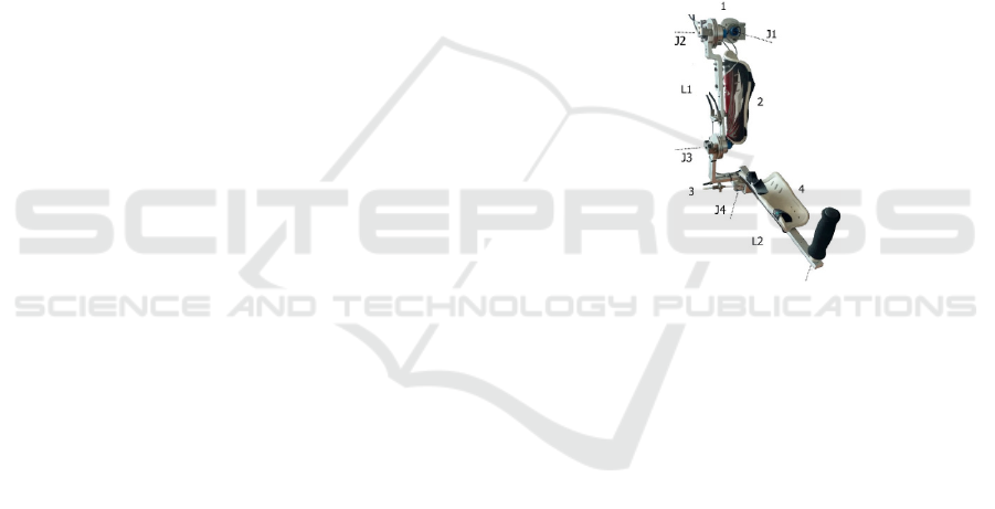
exoskeleton arm prototype is constructed of
aluminum segments (Figure: 1) with variable lengths
for fast and easy adjusting for different user sizes.
Attaching the human arm to segments is done through
soft shells with bands. The exoskeleton arm includes
four segments 1, 2, 3, 4 connected by 4 rotating joints
J1, J2, J3 and J4 with a total of 4 d.o.f., two over the
shoulder and two over the elbow. The masses of the
four segments are M1=0.318 kg, M2=0.367 kg,
M3=0.321 kg and M4=0.194 kg.
The initial arm and forearm lengths are L1=0.286
m and L2=0.370 m. The ranges of the joints J1, J2, J3
and J4 are 110°, 110°, 150°and 135°. The exoskeleton
is designed according to the requirements of the
“activities of daily living” (ADL), as they are rated by
(Perry, 2007) and (Abane, 2016).
Figure 1: Picture of exoskeleton arm prototype.
To build a drive system for one powerful
exoskeleton, the actuators must be big and heavy.
Small, light motors with high gear ratios can also give
enough force, but gears reduce dynamic performance,
so feedback control techniques must be used
(Ermolov, 2016). In the case of an exoskeleton for
rehabilitation, it is assumed that the actuators should
be back drivable, and the exoskeleton should have
low friction and negligible backlash (Garrec, 2008).
To meet these requirements, a pneumatic drive
based on PAMs is used. It provides natural
compliance and safety. It also makes it possible to
adjust the compliance according to the rehabilitation
control strategies. To overcome the limitations of air
muscles and to achieve the full range of therapeutic
interventions, we develop a hybrid type, with
pneumatic and electric drives in parallel.
The joint pneumatics include braided PAMs with
diameter D = 0.016 m and initial length L
n
=0.390 m.
The maximum contraction achieved is C
max
=0.156 m.
Bundles of several muscles, like in (Chakarov, 2017),
are used to easily modify the power and compliance.
Study of a Hybrid Actuated Exoskeleton for Upper Limb Rehabilitation
499
All the muscles of a single PAM actuator are
connected at both ends and fed in parallel through a
single valve. Another valve is used for discharging.
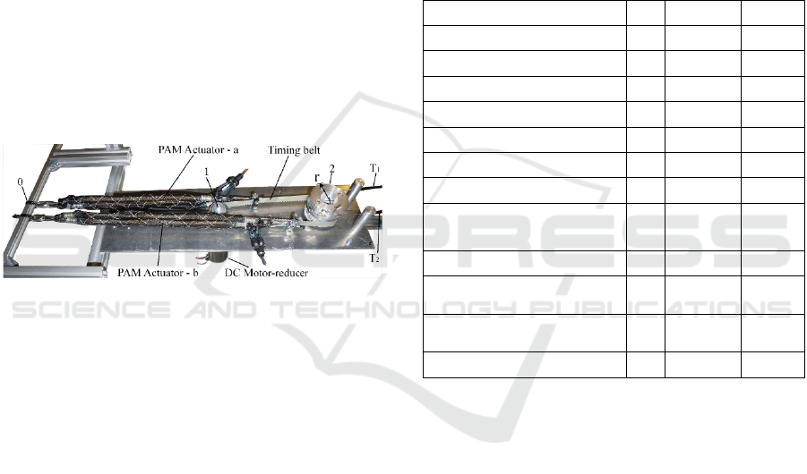
A picture of the actuation prototype with parallel
pneumatic and electric drives is shown in Figure: 2.
In the fixed base 0, there are two wheels 1 and 2
connected to a timing belt. This achieves a gear ratio
of 2: 1. A back drivable DC-motor, coupled with a
low reduction gear, is connected to wheel 1. An
additional washer adapted for winding a cable is
attached to wheel 2. Cable transmissions (Bowden
cables) T
1
and T
2
are used for the coupling between
pulley two and similar pulley mounted in the joint of
the exoskeleton arm. The pneumatic drive consists of
two PAM actuators, "a" and "b" attached at one end
to the fixed base 0 and at the other end to both sides
of the timing belt, as shown in Figure 2. In this way,
PAM actuators work in an antagonistic circuit,
creating a torque of wheel 2. Pressure sensors are
mounted on each supply pipeline. A high precision
rotation sensor is mounted in the exoskeleton joint to
measure the angular displacement.
Figure 2: Joint actuation with parallel pneumatic and
electric drives - picture of the actuation prototype.
The braided PAM behaves as a spring with
variable compliance. A simplified static model is
made used in (Caldwell, 2007) and (Chou, 1996)
simulating a nonlinear quadratic spring. This model
is modified for several muscles in a bundle
(Chakarov, 2017). The forces of the bundles “a” and
“b” are presented with equalities:
q)
)
r(qq))(Cr(q)(Lpk(kP
max
max
max
naa1aoa
(1)
)
)
qq(rL))(qq(rC)(pkk(P
min
n
min
maxb1bbob
(2)
where k
ao
, k
bo
, k
a1
, and k
b1
are empirically discovered
coefficients depending on the muscles count m
a
and
m
b
in the bundle; p
a
and p
b
are the supply pressures of
the bundles; q is the joint angle and r is the pulley
radius. The antagonistic action of the PAM actuators
in each joint creates pneumatically generated torque:
)rP(PQ
abp
(3)
In the design that is considered, the two PAM
bundles "a" and "b" are mounted and include 2 and 4
muscles, respectively, the coefficients have the
following values: k
ao
= 603, k
a1
= 8.61, k
bo
= 1245, and
k
b1
= 17.43.
A back drivable DC-motor coupled with a low
reduction gear is connected to wheel 1 for the parallel
action with the PAM actuators (Figure 2). A low-
inertia Maxon motor EC-i 52 and a NE Nema Series
planetary gearhead with a gear ratio of 10:1 are used.
Since a belt transmission with a gear ratio of 2:1 is
used in the structure, the overall gear ratio of the
transmission from the electric motor to the wheel 2 is
n = 20:1. The parameters of the motor and gearbox
are listed in Table. 1.
Table 1: Motor and gear parameters.
Motor nominal power 180 W
Motor nominal voltage 24 V
Motor nominal torque 434 mNm
Max. motor efficiency η
m
90 %
Motor rotor inertia J
m
170.10
-7
kgm
2
Gearhead reduction 10 : 1
Gearhead efficiency η 89 %
Gearhead inertia J
tr
5.1 10
-7
kgm
2
Gearhead max. accel.
output torque
7 Nm
Belt transmission reduction 2:1
Transmission’s Coulumb
friction
T
c
0.360 Nm
Transmission’s viscous
friction
N 0.250
Nm.s/
ra
d
Radius of pulley 2 r 0.0315 m
3 REHABILITATION
EXOSKELETON CONTROL
The rehabilitation exoskeleton must provide enough
force to assist or resist the motor activity of the patient
or to follow human movements with no resistance
(Jarrasse, 2014). In general, the control of a
rehabilitation exoskeleton can be divided into two
ideal modes that cover the full range of therapeutic
tasks: “robot in charge” and “patient in charge”
(Veneman, 2006). In the "patient-in-charge", the
interactive forces between the exoskeleton and
patient must be close to zero (low perceived robot
impedance). Ideally, if the interactive forces between
the robot and the patient are zero, it means the robot
is completely transparent. In the "robot-in-charge",
the robot must have enough bandwidth and power to
achieve the desired position with high impedance. To
ICINCO 2020 - 17th International Conference on Informatics in Control, Automation and Robotics
500
meet these requirements, an exoskeleton with the
described design is developed, including hybrid
electric and pneumatic drives.
The natural pneumatic drive's impedance takes
care of the initial response in order to provide security
and transparency. The active impedance of the hybrid
actuation creates a subsequent response that is
generated by the force feedback and feed-forward
compensations.
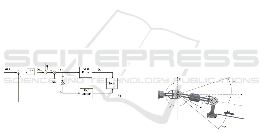
The joint level impedance controller is selected as
shown in the block diagram of Figure: 3. As the
reference for the impedance controller, a trajectory
and an impedance value are selected. The joint
position Δq
d
and joint stiffness K
d
represent the
references in the impedance controller. Feedforward
compensations are also included in the block
diagram. The joint force command (Fig. 3) is
represented by equality:
hfd
QQQQ
(4)
where Q
d
denotes the desired torque in the joint space,
calculated according to the desired joint stiffness K
d
and the difference between the desired and measured
joint position (Δq
d
-Δq); Q
f
denotes the joint force
command according to the impedance feedforward
model; Q
h
denotes the torque of the forces applied by
the patient on the exoskeleton segments.
Figure 3: Impedance controller of the hybrid actuated joint.
By monitoring the pressures p
a
and p
b
of the two
PAM actuators and the joint angle q according to
equations (1), (2) and (3), the pneumatic drive torque
Q
p
can be monitored. The difference between the joint
torque command Q and the real pneumatic drive
torque Q
p
, determines the torque tracking error Q
e
that
is a force command for the electric motor:
pe
QQQ
(5)
An open loop DC motor current controller is used
to achieve the desired joint torque and to compensate
for the slow dynamics of the pneumatic drive.
4 SIMULATION AND
PERFORMANCE EVALUATION
To assess the feasibility of the two main therapeutic
modes, "robot in charge" and "patient in charge"
using the "hybrid actuation approach", dynamic
simulations of a driven joint are conducted. The
dynamics of parallel elastic actuation are evaluated
using cyclic motion (Verstraten, 2016). The
simulations were performed using harmonic motions
with an amplitude q
m
that is imposed on the second
joint J2 of the arm. The law of motion of the position,
velocity, and acceleration is:
0max
q)tsin(qq
(6)
)tcos(qq
max
(7)
)qq()tsin(qq
0
22
max
(8)
where ω is the periodic motion frequency, and q
0
is
the starting position of the arm (Figure: 4). An
uniform frequency variation was chosen in the range
of ω = [1,..., 6] rad/s for time t = [1,…, 6] s. The joint
angle q determines the position of the hand.
Considering that the zero angle is the Y axis, we
conduct the simulations in the angular range of [180
o
-
290
o
] with the primary angle q
0
= 235° and amplitude
q
m
= 55° being the limits of the range of motion.
Figure 4: Exoskeleton arm performing harmonic motion
with amplitude q
m
from starting position q
0.
The resistance torque in the joint, as a result of
motor inertia, exoskeleton inertia, friction, and
gravity is as follows:
gfr
l
J
m
Jr
QQQQQ
(9)
In the above equations, the torque of gravity Q
g
of
the exoskeleton with the mass M
1
and the radius
ρ=[ρ
1
; ρ
2
]
T
of the mass center C is as follows:
]qcossinqg[-MQ
21lg
(10)
where g is the gravity acceleration coefficient.
Study of a Hybrid Actuated Exoskeleton for Upper Limb Rehabilitation
501
The viscous and Coulomb friction torques in the
joint as a result of the friction in the PAM actuators
and in the Bowden cables are as follows:
)q(signTqNQ
cfr
(11)
where N is the viscous friction coefficient, and T
c
is
the Coulomb friction torque. These coefficients are
generalized measures of the different energy effects
in the PAM actuators, Bowden cables, bearings, and
other components for which empirical rather than
analytical estimates are known (Chou, 1996),
(Schiele, 2006).
The inertial members in equation (9) are
represented by the following equations:
q
C
n
)J(JQ
2
trm
m
J
(12)
qJQ
l
l
J
(13)
which express the torques of motor inertia
m
J
Q
and
load inertia
l
J
Q
. Here, J
m
, J
tr
and J
l
are the inertias of
the rotor, of the transmission and of the load,
respectively; and n is the gear ratio. C is gear head
efficiency function, which, according to (Giberti,
2010), gives the effects of the power flow reversal as
follows:
C = 1/η
tr
- the motor drives the load; and
C=η
tr
- the motor is driven by the load.
The simulations were sequentially conducted for
the two main therapeutic modes: “patient in charge”
and “robot in charge”.
4.1 The “Patient in Charge” Mode
In this mode, the authors suggest that the patient has
the motor capacity to move his hand independently.
In passive mode, the electric and pneumatic drives do
not generate active forces. The torque of the forces
that are exerted by the human Q
h
on the exoskeleton
to overcome the exoskeleton mechanical impedance
is determined of the resistance torque (9) involves
inertial, frictional and gravitational forces as well as
elastic forces according to the equation:
pgfr
l
J
m
Jh
QQQQQQ
(14)
Above the torque Q
p
is determined by the elastic
forces of the PAM actuators which are fed by the
given pressures p
a
and p
b
according to (1), (2) and (3).
In the current simulations, Q
p
represents the torque as
a result of the passive stiffness of the pneumatic drive.
It is accepted that the mass and inertia of the load
are equal to those of the exoskeleton, which means
that M
1
=M
e
and J
1
= J
e
, respectively. The total mass
of the exoskeleton’s moving parts 2,3 and 4 are M
е
=
0.882 kg, and the coordinates of the mass center C are
ρ = [0.219; 0.039]
T
(Figure: 4). The inertia of the
exoskeleton arm to the axis of joint J2 is J
e
= 0.061
kgm
2
. The values of the remaining mechanical
parameters from (11) and (12) are shown in Table 1.
The gearbox efficiency function is C = η, (the motor
is driven by the patient). The described patient-
initiated harmonic motion in equations (6), (7), and
(8) is examined using an increasing frequency.
Adopted is an amplitude of movements of q
m
= 55°
from the initial position q
0
= 235°.
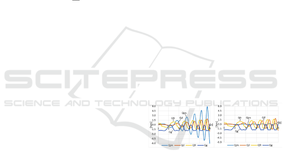
The change of the torque of motor inertia (12) and
the torque of load inertia (13), as well as the torques
of viscous and Coulomb friction (11), are shown in
Figure: 5. These torques are independent of the arm
position but depend on the oscillation frequency. The
graph also shows the change in the torque of gravity
(10) that depends mainly on the position of the arm.
Figure: 5 (a) and (b) shows the effect of the gear ratio
for n = 90 and n = 20 respectively. Increasing the gear
ratio significantly increases the influence of the
torque of motor inertia. Then, at "patient in charge",
the faster patient initiated motions are associated with
higher interaction forces. In the studied exoskeleton,
a gear ratio n = 20 was chosen, and the resistance
torques are shown in Figure:5(b).
Figure 5: Resistance joint torques according to (9), which
are generated by the patient’s harmonic motion with a
uniform increase in the frequency and ratio of the joint gear:
a) n = 90 and b) n = 20.
Fluctuation in the total joint resistance (9) is
shown in the graph in Figure: 6. At low frequencies,
it is mainly a result of gravitational loads, and at high
frequencies, it results mainly from inertial loads.
The graph of Figure: 6 also shows the passive
torque of the pneumatic drive Q
p
. It is calculated
according to (1), (2), and (3), where q
0
+q
m
determines
the maximum position q
max
for one PAM actuator and
the minimum position q
min
for the other, respectively
q
0
-q
m
determines q
min
and q
max
. In this workspace
position (q
0
= 235 °), the pressure of the two PAM
actuators is selected, respectively p
a
= 10 kPa and p
b
ICINCO 2020 - 17th International Conference on Informatics in Control, Automation and Robotics
502
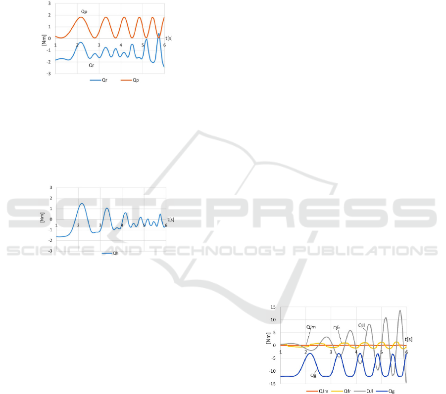
= 0. The pneumatic drive acts as an elastic balancer
of the gravity load. The torque of the elastic forces of
the PAM actuators oscillates with the oscillations of
the position, but its average is constant. The
resistance torque is mainly compensated by the torque
of the elastic forces. In another position of the
workspace, such compensation can be achieved by
other pressures of the PAM actuators.
Figure 6: Torque of total joint resistance Q
r
and torque of
pneumatic drive Q
p
.
The total torque calculated according to equation
(14) is shown in Figure: 7. It represents the torque of
the interaction forces that are applied to the hand of
the patient initiating the movement. The simulation
shows that this torque does not exceed 1.6 Nm.
Figure 7: Torque of the interaction forces that are applied
to the hand of the patient initiating the movement.
In active mode, according to the control scheme
of Figure: 3, the resistance torque in the joint (9) as a
result of exoskeleton mechanical impedance is
considered to be a reference for the feedforward
compensations Q
f
= Q
r
. In order to obtain complete
transparency for the patient Q
h
=0, assuming that Q
d
=
0, the joint force command (4) will have the form Q
= Q
r
. This command is assigned for the
implementation of the hybrid pneumatic and electric
drive.
4.2 The “Robot in Charge” Mode
In this mode, the authors suggest that the patient does
not resist Q
h
=0 (fully immobilized patient). This is an
active mode in which the joint force command is
determined according to the hybrid control scheme of
Figure: 3. The resistance torque in the joint (9)
determined by the patient’s and the exoskeleton’s
impedance as inertial, friction and gravitational forces
is considered to be a reference for the feedforward
compensations Q
f
= Q
r
. Assuming that Q
d
= 0,
according to (4) and (5), the joint force command to
the electric drive will be as follows
pgfr
l
J
m
Jе
QQQQQQ
(15)
The joint actuators drive the exoskeleton arm and
the patient's hand. The mass and inertia of the
patient's hand are combined with those of the
exoskeleton as a whole. The mass-inertial
characteristics of the upper limb are selected
according to (Tözerem, 2000) and are given in
percentages with respect to the weight of the
individual. For a human that weighs 70 kg, the upper
limb’s mass (arm, forearm, and hand) is M
h
= 3.472
kg, the coordinates of the mass center are ρ
h
= [0.298;
0]
T
m and the upper limb’s inertia to the axis of joint
J2 is J
h
= 0.533 kg m
2
. The total mass of the load is
M
1
= M
e
+ M
h
= 4.354 kg, the mass center coordinates
are ρ = [0.283; 0.008]
T
, and the total inertia is J
l
= J
e
+ J
h
= 0.594 kg m
2
.
The motor drives the load and then the efficiency
function has the form C=1/η. The values of the other
mechanical parameters from equations (11) and (12)
are shown in Table 1. Harmonic movements are
simulated using equations (6), (7), and (8) with an
increasing frequency and an amplitude of q
m
= 40°
over the initial position q
0
= 235°. Figure: 8 shows the
variation of the motor’s inertial torque (12), the total
load’s inertial torque (13), the viscous and Coulomb
friction torque (11) and the torque of the total gravity
(10). Figure: 9 shows the sum of the torques (10),
(11), (12), and (13) as the total resistance in the joint
according to equation (9).
Figure 8: Torques from motor’s inertia Q
Jm
, total load’s
inertia Q
Jl
, viscous and Coulomb friction Q
fr
, and gravity of
the total load Q
g
, which are generated by the harmonic joint
motion with a uniform increase in the frequency.
To overcome the resistive torque in the joint, the
control algorithm creates a command for a desired
torque to the pneumatic drive. It is set by determining
the pressures p
a
and p
b
of the PAM actuators,
according to (1), (2), and (3). Due to the slow force
response of the PAM actuators, the pneumatic
Study of a Hybrid Actuated Exoskeleton for Upper Limb Rehabilitation
503
actuation mainly performs the low-frequency part of
the job. For this reason, in the simulation performed,
the torque of pneumatic actuation is considered to be
the result of constant supply pressures. Thus, Figure:9
shows the variation of the pneumatic drive torque Q
p
for the pressures p
a
= 300 kPa and p
b
= 0. At these
pressures and at a set position, for example, q
0
= 235
o
,
the pneumatic drive acts as an elastic gravity load
balancer. However, when the arm is diverted from
this position, passive torque is generated due to the
elastic deviation in the PAM actuators. In the
simulations that were performed, the maximum value
of the elastic deviations is set (q
m
= 40
o
) for which the
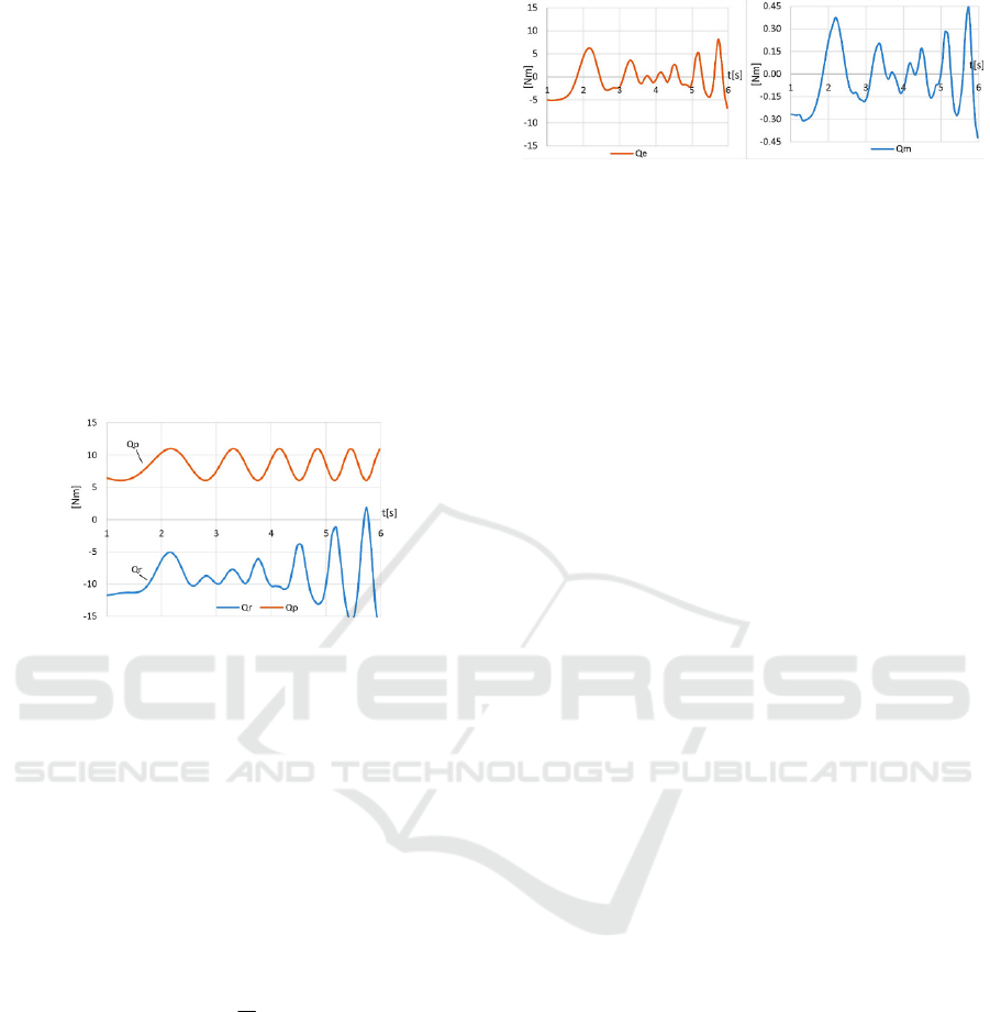
torque variations are evaluated. The resultant torque
in the joint, according to (15) is shown in Fig.10. This
is a command to the electric drive.
Figure 9: Total resistance in the joint Q
r
as a sum of the
torques Q
Jm
, Q
Jl
, Q
fr
and Q
g
as well the pneumatic drive
torque Q
p
at the PAM actuator pressures of p
a
= 300 and p
b
= 0 kPa.
It is seen from Figure:10 a) that the resulting joint
torque (15) in its main part is compensated by the
pneumatic drive. As a force command to the electric
drive, the torque Q
e
will complement the pneumatic
drive. Figure: 10 b) shows the electric drive torque Q
m
when it is calculated according to (16) with respect to
the axis of the motor, taking into account the gearbox
efficiency function C and the gear ratio n:
n
C
QQ
em
(16)
The simulations show that with respect to the
performance of the cyclical movements over the
position q
0
= 235° with an amplitude q
m
= 40° and a
frequency up to 6 rad/s, the electric motor’s torque Q
m
does not exceed the motor nominal torque, as shown
in Table 1. It also includes compensation for the
elastic forces of parallel pneumatic drive. This is an
extreme case since the actual pneumatic drive also
performs the set force command so that the joint
hybrid drive has the capacity to perform the desired
joint torque.
Figure 10: Resulting joint torque as a command: a) to the
axis of the joint; b) to the axis of the motor.
5 DISCUSSION
In the simulations performed, the patient-initiated
interaction torque is determined by passive forces,
such as inertial, friction, and gravitational forces, and
by the elasticity of the pneumatics (14). This is an
extreme case of patient load. With active control
(Figure: 3), the torque from the electric drive Q
e
seeks
to compensate for the torque in equation (14).
However, safety and transparency are guaranteed by
the low values of this torque that are obtained without
feedback and active control. These values are a result
of the passive approach in the design of a
rehabilitation exoskeleton, which is built using
lightweight parts, low geared motors, and compliant
PAM actuators acting as gravity compensators.
The peak values of the resulting joint torques, as
represented in Figure: 7 and Figure: 10, at low
frequencies are mainly influenced by the gravity and
the elasticity of the PAM actuators, while at high
frequencies, they are mainly due to the inertial forces
of the exoskeleton and the patient. For low-frequency
rehabilitation tasks, the torque can be compensated by
a feedforward control based only on the gravity
models and the models of the elasticity of the
pneumatic actuators. For high-frequency tasks, the
compensation should include inertial models, and
measuring or calculating the joints’ acceleration.
The experiment shows that using the hybrid drive
approach, the pneumatic drive relieves the electric
drive by compensating mainly for the gravitational
loads. The natural compliance of this drive, however,
results in elastic forces that are compensated by the
electric drive. When the pressure of the pneumatic
actuators is low, such as in the “patient in charge”
mode, the magnitude of the force command to the
electric drive is not high. Increasing the pressure in
the pair of pneumatic actuators, such as in the “robot
in charge mode”, increases the passive stiffness in the
joint and hence increases the magnitude of the elastic
force.
ICINCO 2020 - 17th International Conference on Informatics in Control, Automation and Robotics
504

6 CONCLUSIONS
In this paper, an upper arm exoskeleton for
rehabilitation and training is studied. An appropriate
solution is sought for the exoskeleton design and
actuation that provides transparency and natural
safety on the one hand and force impact and
performance on the other hand. A hybrid actuation
approach is used, which consists of back drivable
electric and pneumatic drives operating in parallel. In
the paper, the feasibility of the basic therapy modes
“patient in charge” and “robot in charge” is simulated.
The approach for the dynamic estimation of elastic
actuation through imposed motions is used.
Harmonic motion with a uniform increase in the
frequency in the second joint is simulated. In the
"patient in charge" mode, the resistive torque of the
passive impedance is seen as the interaction torque
that is applied to the patient's hand. In the “robot in
charge” mode, the resistive torque is used to assign
force commands to the electric drive to perform
feedforward compensations. Future exoskeleton
experiments are planned in which the real parameters
of the harmonic movements should be measured and
evaluated.
ACKNOWLEDGEMENTS
This research was supported by the National Science
Fund, Project No. DN07/9 and by the Nat. Scientific
Program ICTinSES, Contract No DO1–205.
REFERENCES
Jarrasse N, Proietti T, Crocher V, et al., 2014. Robotic
Exoskeletons: A Perspective for the Rehabilitation of
Arm Coordination in Stroke Patients. Frontiers in
Human Neuroscience , Vol.8, Art.947: 1-13.
Hogan N, Krebs HI, et al., 2006. Motions or muscles? Some
behavioral factors underlying robotic assistance of
motor recovery. J. Rehabil. Res. Dev., 43: 605–618.
Bergamasco M, Allotta B, Bosio L, et al.,1994. An Arm
Exoskeleton System for Teleoperation and Virtual
Environment Applications. IEEE Int’l Conf. Robot.
Automat; 2: 1449–1454.
Carignan C.R. and Cleary K.R., 2000. Closed- Loop Force
Control for Haptic Simulation of Virtual Environments.
Haptics-e, February 23, Vol. 1, No. 2: 1-14.
Veneman JF, Ekkelenkamp R, Kruidhof R, et al., 2006. A
series elastic and bowden cable based actuation for use
as torque actuator in exoskeleton-type robots. The Int.
Journal of Robotics Research; 25(3): 261-281.
Verstraten T, Beckerle P, Furnémont R, et al., 2016. Series
and Parallel Elastic Actuation: Impact of natural
dynamics on power and energy consumption.
Mechanism and Machine Theory; 102: 232–246.
Daerden Fr. and Lefeber D., 2002. Pneumatic Artificial
Muscles: actuators for robotics and automation. Europ.
J. of Mech. and Environmental Engineering; 47,1:1–11.
Caldwell D., Tsagarakis N., 2007. “Soft” exoskeletons for
upper and lower body rehabilitation- design, control
and testing. Int. J. of Humanoid Robot., 4(3): 549–573.
Sardellitti I., Park J., Shin D., Khatib O., 2007. Air muscle
controller design in the distributed macro-mini (DM2)
actuation approach. IEEE/RSJ Int. Conf. on Intellig.
Rob. and Systems, San Diego, CA : 1822–1827.
Noda T., Teramae T., et al., 2014. Development of an upper
limb exoskeleton powered via pneumatic electric
hybrid actuators with Bowden cable, IEEE/RSJ. Int.
Conf. on Intelig. Rob. and Systems, Chicago, IL: 3573
– 3578.
Aguilar-Sierra H, Yu W, Salazar S., Lopez R., 2015. Design
and control of hybrid actuation lower limb exoskeleton.
Adv. in Mech. Engineering, 7(6): 1–13.
Shin D., Yeh X., Khatib O., 2014. A new hybrid actuation
scheme with artificial pneumatic muscles and a
magnetic particle brake for safe human– robot collabor.
The Int. Journ. of Robics Research., 33(4): 507–518.
Perry J., Rosen J. and Burns S., 2007. Upper-limb powered
exoskeleton design. IEEE/ASME Trans. on
Mechatronics; Vol.12, No. 4: 408–417.
Abane, A., Guiatni, M. et al., 2016. Mechatronics Design,
Modeling and Preliminary Control of a 5 DOF Upper
Limb Active Exoskeleton, 13 th Int. Conf. on Inform. in
Control, Autom. and Rob. (ICINCO 2016), 2: 398-405.
Ermolov, I., Knyazkov, et al., 2016. The Dead Zone
Determination for Exoskeleton Arm with Double Mode
Control System. 13th Int. Conf. on Inform. in Control,
Autom. and Rob. (ICINCO 2016), 2: 274-279.
Garrec P., Friconneau J., Measson Y., Perrot Y., 2008.
Able, an innovative transparent exoskeleton for the
upper-limb, IEEE/RSJ Int. Conference on Intelligent
Robots and Systems (IROS 2008): 1483–1488
Chakarov D., Veneva Iv., et al., 2017. Design and Control
of a Force Reflecting Arm Exoskeleton for Virtual
Reality Applications. 14th Int. Conf. on Inform. in
Contr., Aut. and Rob., (ICINCO 2017), 2/102: 335-342.
Chou P., Hannaford B., 1996. Measurement and Modeling
of McKibben Pneumatic Artificial Muscles. IEEE
TRANS on Robotics and Automation, Vol.12, No1: 1-
22.
Schiele A., Letier P. et al., 2006. Bowden cable actuator for
force-feedback exoskeletons. IEEE Int. Conf. on
Intelligent Robots and Systems: 3599-3604.
Giberti H, Cinquemani S, and Legnani G., 2010. Effects of
transmission mechanical characteristics on the choice
of a motor-reducer. Mechatronics; 20(5): 604–610.
Tözerem A., 2000. Human Body Dynamics: Classical
Mechanis and Human Movements. Berlin Heidelberg:
Springer-Verlag, p.316.
Study of a Hybrid Actuated Exoskeleton for Upper Limb Rehabilitation
505
