
Parameter Estimator for Twin Rotor MIMO System based on DREM
Procedure
Nikita Shopa
1 a
, Dmitry Bazylev
1 b
, Sergey Vrazhevsky
1,2 c
and Artem Kremlev
1 d
1
Faculty of Control Systems and Robotics, ITMO University, St. Petersburg, Russia
2
The Laboratory ”Control of Complex Systems”, Institute for Problems in Mechanical Engineering of the Russian Academy
of Sciences (IPME RAS), St. Petersburg, Russia
Keywords:
Parameter Identification, Nonlinear Systems, Multi-channel Systems, Linear Regression.
Abstract:
The paper deals with a problem of parameter identification for a model of Twin Rotor MIMO System labora-
tory bench, which is described by a nonlinear multi-channel system with cross-couplings. The chosen method
is based on the Dynamic Regressor Extention and Mixing (DREM) procedure that guarantees monotonic con-
vergence of the estimations even in case of multiple related parameters simultaneously identification. Results
are verified by computer simulation.
1 INTRODUCTION
Parameter uncertainties is an anticipated problem in
the practice area of control. Model-based control al-
gorithms, including adaptive control techniques, re-
quire to improve estimation approaches. One of the
modern approaches that ensure fast estimation con-
vergence with high-quality transients is developed in
(Aranovskiy et al., 2016). This paper (Aranovskiy
et al., 2016) describes the so-called Dynamic Regres-
sor Extention and Mixing (DREM) procedure which
is synthesized in two steps. The first is an additional
filtering data process that extends the standard linear
regression model. In the second step, an extended
regressor model is transformed in a way it became
possible to apply standard estimation techniques in-
dependently for each unknown parameter. This new
property ensures faster transients without overshoot-
ing, unlike the classical gradient method (Aranovskiy
et al., 2016). Another important property of DREM
is a possibility to avoid the persistency of excitation
(PE) condition, which is one of the main restrictions
for identification and adaptive control theories. In-
stead of PE condition, DREM procedure requires not
square-integrable condition satisfaction.
Result (Aranovskiy et al., 2016) demonstrates
a
https://orcid.org/0000-0001-7518-6346
b
https://orcid.org/0000-0003-4416-5731
c
https://orcid.org/0000-0001-9725-5330
d
https://orcid.org/0000-0002-7024-3126
high quality in wide area of practical and theoreti-
cal tasks. Besides the original idea of using linear
stable dynamic operators to obtain an extended re-
gressor, modifications have been proposed that con-
struct extended regressor using time-delay operators
(Bazylev et al., 2018a). DREM procedure was suc-
cessfully applied in the task of multi-harmonic dis-
turbances identification and to ensure the stability of
quantized systems in (Dobriborsci et al., 2019a). In
the research (Bobtsov et al., 2017), DREM approach
is extended to the problem of position estimation as
a state observer, which significantly improves an ap-
plication area of the method. In practice, there are
solutions of sensorless control algorithms applied to
a motor control based on DREM in (Bazylev et al.,
2018b).Some rubust properties against measurement
noises were demonstrated in (Bobtsov et al., 2017)
and (Bazylev et al., 2018b).
Current research deals with a problem of parame-
ter identification of laboratory platform named Twin
Rotor MIMO System (TRMS). The platform realises
the dynamics of rotary-wing aircraft in two planes
- pitch and yaw. It has complex nonlinear dynam-
ics with cross-coupling and parametrical uncertainties
which reduce the tracking accuracy of the closed-loop
system. There are researches dealing with a problem
of TRMS modelling including parameter identifica-
tion task (see, for example, (Rahideh et al., 2008)),
however, this researches keep identification problem
apart from the control task. As soon as parametri-
cal uncertainties can appear during the technical plant
Shopa, N., Bazylev, D., Vrazhevsky, S. and Kremlev, A.
Parameter Estimator for Twin Rotor MIMO System based on DREM Procedure.
DOI: 10.5220/0009875506890694
In Proceedings of the 17th International Conference on Informatics in Control, Automation and Robotics (ICINCO 2020), pages 689-694
ISBN: 978-989-758-442-8
Copyright
c
2020 by SCITEPRESS – Science and Technology Publications, Lda. All rights reserved
689

functioning, current research proposes a more conve-
nient way to deal with it. Another motivation of test-
ing DREM approach on TRMS platform is to examine
accuracy of identification in case of parallel identifi-
cation of parameters of two separate subsystems of
the same plant with cross reactions.
The article is organized as follows. Section 2 de-
scribes the mathematical model of TRMS. Section 3
considers DREM implementation for TRMS. Com-
puter modelling results are shown and discussed in
Section 4.
2 TWIN ROTOR MIMO SYSTEM
MODEL
”Twin Rotor MIMO System” laboratory platform is a
helicopter-like setup designed for testing various con-
trol approaches. The structure of TRMS is shown on
fig.1.
Figure 1: The structure of Twin Ritir MIMO System.
TRMS dynamics include nonlinearities, cross-
reactions, and parametrical uncertainties. There are
two known basic mathematical models of TRMS
(Feedback Instruments, 1998), (Feedback Instru-
ments, 2006). In the first paper, experimental ap-
proximations for nonlinear functions of electrical cir-
cuits and aerodynamic forces influence are proposed.
This model also considers well-described mass and
weight parameters information. The model in (Feed-
back Instruments, 2006) gives cross-couplings defini-
tions and nonlinear aerodynamic forces function de-
scriptions instead of approximations in (Feedback In-
struments, 1998). Most of the papers dealing with
TRMS are usually based on one of them. For exam-
ple, in (Huang, 2011) authors use the first model to
construct a new robust control scheme. In (Rahideh
and Shaheed, 2009) a robust model predictive control
algorithm is developed in accordance with the sec-
ond model. In (Rahideh et al., 2008) an empirical
modelling approach is compared with the model from
(Feedback Instruments, 2006) and the high quality of
the obtained models is shown. In this paper, the first
TRMS model is used. The model there is not based
on an experimental approximation which makes re-
search of identification approaches more logical. It
should be noted, that despite the differences between
the descriptions in (Feedback Instruments, 1998) and
(Feedback Instruments, 2006), both models are based
on the same physical principles and correlate with
each other well. We assume that the results given in
the current research can be reproduced with respect
to (Feedback Instruments, 2006) without significant
changes.
The full dynamical model of TRMS is defined by
(
J
1
¨
α = M
1
− M
B1
− M
FG
− M
G
,
J
2
¨
β = M
2
− M
B2
− M
R
,
(1)
where J
1
and J
2
are inertia moments; M
1
(τ
1
) and
M
2
(τ
2
) are moments of control influence for both
pitch (produced by the main motor) and yaw (tail mo-
tor) subsystems; M
B1
(
˙
α), M
B2
(
˙
β) are friction forces
moments; M
FG
(α) is a gravity moment; M
G
(τ,α,
˙
β)
and M
R
(τ
1
) are cross-reactions; τ
1
(u
1
) and τ
2
(u
2
) are
torque moments of DC motors and u
1
, u
2
are voltage
levels on DC motor terminals. All functions are spec-
ified as follows:
M
1
= a
1
τ
2
1
+ b
1
τ
1
,
M
2
= a
2
τ
2
2
+ b
2
τ
2
,
M
B1
= B
1
˙
α,
M
B2
= B
2
˙
β,
M
FG
= M
g
sin(α),
M
G
= K
g
M
1
˙
βcos(α),
M
R
=
k
c
(T
0
s + 1)
T
p
s + 1
τ
1
,
τ
1
=
k
1
T
11
s + T
20
u
1
,
τ
2
=
k
1
T
21
s + T
20
u
2
.
The first equation of (1) describes the plant dy-
namic in the vertical plane and the second equation of
(1) does the same for the horizontal plane. It should
be noted that the TRMS platform realizes output con-
trol only and signals
˙
α and
˙
β are unknown which is
important for identification approaches as well. Nu-
merical values of plant parameters are in accordance
with documentation (Feedback Instruments, 2006)
and shown in Table 1. However, while there are pa-
rameters that are determined with high accuracy, there
also exist parameters needed to be clarified. Friction
force moment coefficients B
1
and B
2
belong to a set of
uncertain parameters. This is caused by the fact that
friction forces momentum coefficients can be changed
by tuning mechanical parts of TRMS platform and
ICINCO 2020 - 17th International Conference on Informatics in Control, Automation and Robotics
690

changed during functioning. From another side, grav-
ity moment parameters, as well as control functions
parameters, are known, because mass, weight and
electrical parameters of TRMS can be measured and
evaluated accurately.
Table 1: Twin Rotor MIMO System Parameters.
Parameter Value
J
1
0.068 [kg · m
2
]
J
2
0.02 [kg · m
2
]
B
1
0.006 [H · m ·s/rad]
B
2
0.1 [H · m ·s/rad]
a
1
0.0135 [n/a]
b
1
0.0924 [n/a]
a
2
0.02 [n/a]
b
2
0.09 [n/a]
M
g
0.32 [H · m]
K
g
0.05 [s/rad]
k
1
1.1 [n/a]
k
2
0.8 [n/a]
T
11
1.1 [n/a]
T
10
1 [n/a]
T
21
1 [n/a]
T
20
1 [n/a]
3 PROBLEM STATEMENT
The task is to identify unknown parameters of a non-
linear MIMO plant and to ensure an asymptotic con-
vergence of identification errors to zero. Define a goal
lim
t→∞
k
˜q
p
k
= 0,
lim
t→∞
k
˜q
y
k
= 0,
(2)
where ˜q
p
= ˆq
p
−q
p
, ˜q
y
= ˆq
y
−q
y
are identification er-
rors, q
p
= [J
1
;B
1
]
T
and q
y
= [J
2
;B
2
]
T
are vectors of
unknown parameters of the plant (1), ˆq
p
= [
ˆ
J
1
;
ˆ
B
1
]
T
and ˆq
y
= [
ˆ
J
2
;
ˆ
B
2
]
T
are estimates of q
p
and q
y
respec-
tively.
In the current research, we define the following set
of TRMS parameters which need to be estimated: B
1
,
B
2
, J
1
, J
2
. The motivation of choosing the parame-
ters is explained by the idea that friction forces coef-
ficients need to be estimated to improve the accuracy
of model-based control algorithms while inertia mo-
ments values are known and can be used to determine
the accuracy of the identification method itself.
4 PARAMETER
IDENTIFICATION METHOD
Rewrite equation (1) in a convenient form
(
M
1
− M
FG
− M
G
= J
1
¨
α + M
B1
,
M
2
− M
R
= J
2
¨
β + M
B2
.
(3)
Since signals
˙
α,
¨
α,
˙
β,
¨
β can’t be measured, it is
possible to apply a stable linear filter F(s) =
a
(s+a)
2
with the parameter a > 0 to the model (3), which
makes possible to reproduce unknown signals and
construct a standard linear regression model. Other-
wise, DREM technique could be applied immediately.
Applying F(s), we get
(
a
(s+a)
2
[M
1
− M
FG
− M
G
] = J
1
as
2
(s+a)
2
[α] + B
1
as
(s+a)
2
[α],
a
(s+a)
2
[M
2
− M
R
] = J
2
as
2
(s+a)
2
[β] + B
2
as
(s+a)
2
[β].
Substitute moments descriptions and introduce
new variables for (3)
g
p
=
a
(s + a)
2
[a
1
τ
2
1
+ b
1
τ
1
− M
g
sin(α) − pK
g
M
1
βcos(α)]
g
y
=
a
(s + a)
2
[a
2
τ
2
2
+ b
2
τ
2
−
k
c
(T
0
s + 1)
T
p
s + 1
τ
1
],
m
p
= [
as
2
(s + a)
2
[α];
as
(s + a)
2
[α]]
T
,
m
y
= [
as
2
(s + a)
2
[β];
as
(s + a)
2
[β]]
T
,
where functions m
p
, m
y
, g
p
and g
y
are the mea-
surable. In accordance to the goal (2), vectors of un-
known parameters are defined by q
p
= [J
1
;B
1
]
T
and
q
y
= [J
2
;B
2
]
T
and, following the replacement before,
we get the standard linear regression models
g
p
= m
T
p
q
p
,
g
y
= m
T
y
q
y
.
(4)
At the current step of the model analysis, the
DREM procedure can be applied in two steps.
4.1 Step 1
Applying a new filter satisfies the Hurwitz condition
and defined by H(s) =
b
(s+b)
2
with the parameter b > 0
to the regression model (4), we get a second set of
linear regression models in the following form
¯g
p
= ¯m
T
p
q
p
,
¯g
y
= ¯m
T
y
q
y
,
(5)
where ¯g
p
= H(s)g
p
, ¯g
y
= H(s)g
y
, ¯m
p
= H(s)m
p
, ¯m
y
=
H(s)m
y
.
Parameter Estimator for Twin Rotor MIMO System based on DREM Procedure
691

4.2 Step 2
Construct an extended linear regression model in the
form
G
p
= M
p
q
p
,
G
y
= M
y
q
y
,
(6)
where
G
p
=
g
p
¯g
p
,M
p
=
m
p1
m
p2
¯m
p1
¯m
p2
,
G
y
=
g
y
¯g
y
,M
y
=
m
y1
m
y2
¯m
y1
¯m
y2
.
Multiplying (6) by adjoint matrices
ad j{M
p
} =
¯m
p2
−m
p2
− ¯m
p1
m
p1
,
ad j{M
y
} =
¯m
y2
−m
y2
− ¯m
y1
m
y1
,
model (6) takes the representation
ad j{M
p
}
g
p
¯g
p
= ad j{M
p
}
m
p1
m
p2
¯m
p1
¯m
p2
J
1
B
1
,
ad j{M
y
}
g
y
¯g
y
= ad j{M
y
}
m
y1
m
y2
¯m
y1
¯m
y2
J
2
B
2
.
After the following calculations
ad j{M
p
}G
p
=
¯m
p2
g
p
− m
p2
¯g
p
m
p1
¯g
p
− ¯m
p1
g
p
,
ad j{M
p
}M
p
=
¯m
p2
m
p1
− m
p2
¯m
p1
0
0 ¯m
p2
m
p1
− m
p2
¯m
p1
,
ad j{M
y
}G
y
=
¯m
y2
g
y
− m
y2
¯g
y
m
y1
¯g
y
− ¯m
y1
g
y
,
ad j{M
y
}M
y
=
¯m
y2
m
y1
− m
y2
¯m
y1
0
0 ¯m
y2
m
y1
− m
y2
¯m
y1
,
we get a set of separate independent regression mod-
els for each unknown parameter in both subsystems
defined by
¯m
p2
g
p
− m
p2
¯g
p
= ( ¯m
p2
m
p1
− m
p2
¯m
p1
)J
1
,
m
p1
¯g
p
− ¯m
p1
g
p
= ( ¯m
p2
m
p1
− m
p2
¯m
p1
)B
1
,
¯m
y2
g
y
− m
y2
¯g
y
= ( ¯m
y2
m
y1
− m
y2
¯m
y1
)J
2
,
m
y1
¯g
y
− ¯m
y1
g
y
= ( ¯m
y2
m
y1
− m
y2
¯m
y1
)B
2
.
(7)
The model (7) considers separate regression mod-
els for both TRMS subsystems with independent rep-
resentation for each unknown parameter. A standard
gradient method for a problem of multiple parameter
estimation does not allow obtaining independent re-
gression equations for each unknown parameter. That
new property of DREM increases estimates conver-
gence speed and transient accuracy (Aranovskiy et al.,
2016). Rewrite
ε
p1
= ¯m
p2
g
p
− m
p2
¯g
p
,
ε
p2
= m
p1
¯g
p
− ¯m
p1
g
p
,
ε
y1
= ¯m
y2
g
y
− m
y2
¯g
y
,
ε
y2
= m
y1
¯g
y
− ¯m
y1
g
y
,
ϕ
p
= ¯m
p2
m
p1
− m
p2
¯m
p1
,
ϕ
y
= ¯m
y2
m
y1
− m
y2
¯m
y1
,
and transform (7) in the set of scalar regressions
ε
p1
= ϕ
p
q
p1
,
ε
p2
= ϕ
p
q
p2
,
ε
y1
= ϕ
y
q
y1
,
ε
y2
= ϕ
y
q
y2
,
where q
p1
= J
1
, q
p2
= B
1
, q
y1
= J
2
, q
y2
= B
2
are un-
known parameters which need to be determined. In-
troduce scalar gradient estimators as follows
˙
ˆq
p1
= γ
p1
(ε
p1
ϕ
p
− ϕ
2
p
ˆq
p1
),
˙
ˆq
p2
= γ
p2
(ε
p2
ϕ
p
− ϕ
2
p
ˆq
p2
),
˙
ˆq
y1
= γ
y1
(ε
y1
ϕ
y
− ϕ
2
y
ˆq
y1
),
˙
ˆq
y2
= γ
y2
(ε
y2
ϕ
y
− ϕ
2
y
ˆq
y2
),
(8)
where γ
p1
> 0, γ
p2
> 0, γ
y1
> 0, γ
y2
> 0 are adaptation
coefficients.
A convergence of estimates in (8) is ensured by
the proof of the following proposition (in accordance
with (Aranovskiy et al., 2016)).
Proposition 1. Consider the parametrized TRMS
model (7). There exist parameters γ
p1
> 0, γ
p2
> 0,
γ
y1
> 0, γ
y2
> 0 such that the adaptation law (8) sat-
isfies the goal (2) and provides an exponential con-
vergence of signals ˜q
p
= ˆq
p
− q
p
, ˜q
y
= ˆq
y
− q
y
to 0
if the functions ϕ
p
(t), ϕ
y
(t) are persistently excited,
ϕ
p
(t),ϕ
y
(t) ∈ PE. If ϕ
p
(t), ϕ
y
(t) are not square in-
tegrable, ϕ
p
(t),ϕ
y
(t) /∈ L
2
, then ˜q
p
= ˆq
p
− q
p
, ˜q
y
=
ˆq
y
− q
y
tend to 0 asymptotically.
Proof. Derivatives of ˜q
p
, ˜q
y
in scalar form take a rep-
resentation
˙
˜q
p1
= −γ
p1
ϕ
2
p
˜q
p1
,
˙
˜q
p2
= −γ
p2
ϕ
2
p
˜q
p2
,
˙
˜q
y1
= −γ
y1
ϕ
2
y
˜q
y1
,
˙
˜q
y2
= −γ
y2
ϕ
2
y
˜q
y2
.
Solving equations above we immediately see that
˜q
p1
= e
−γ
p1
R
t
0
ϕ
2
p
(s)ds
˜q
p1
(0),
˜q
p2
= e
−γ
p2
R
t
0
ϕ
2
p
(s)ds
˜q
p2
(0),
˜q
y1
= e
−γ
y1
R
t
0
ϕ
2
y
(s)ds
˜q
y1
(0),
˜q
y2
= e
−γ
y2
R
t
0
ϕ
2
y
(s)ds
˜q
y2
(0),
which completes the proof.
ICINCO 2020 - 17th International Conference on Informatics in Control, Automation and Robotics
692
5 SIMULATION RESULTS
Computer simulation consists of two parts. First,
the plant model is tested by generating input sig-
nals which ensure a diverse informative output of (1).
Such behavior is reached by constructing a control
system which consists of the plant (1) and a PID con-
troller described by
u
1
= 5e
α
+ 10 ˙e
α
+ 8
Z
t
0
e
α
(s)ds,
u
2
= 2e
β
+ 5 ˙e
β
+ 0.5
Z
t
0
e
β
(s)ds,
(9)
that provides tracking stability against following ref-
erence signals
α
re f
= 0.5 sgn(sin(πt)),β
re f
= 0.3 sgn(sin(πt)).
PID controller parameters are chosen equal to
the values presented in the official documentation of
TRMS (Feedback Instruments, 2006). Reference sig-
nals are chosen to ensure the sustained excitation con-
dition. Output and input signals are shown in fig. 2-3.
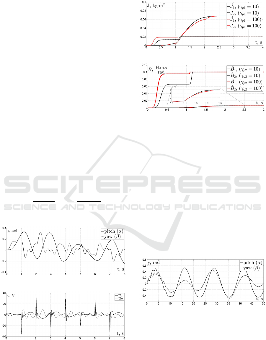
Figures 4-5 show the results of the estimation of in-
ertia moments (Fig. 4) and friction forces coefficients
(Fig.5) with various parameter γ values which deter-
mines a convergence rate. The following parameters
of gradient estimators and filters are chosen:
F(s) =
10
(s + 10)
2
,H(s) =
100
(s + 100)
2
,
γ
p1
= γ
p2
= γ
y1
= γ
y2
= {10; 100}.
(10)
Figure 2: Output signals used for the identification.
Figure 3: Input signals used for the identification.
In practice, a closed-loop system in tracking mode
usually provides less variability of input and output
signals reasoned by physical constraints on signal
Figure 4: Inertia moments estimation results.
Figure 5: Friction forces estimation results.
magnitudes and specific control requirements. Fol-
lowing practical relevance, DREM is tested on con-
trol system which consists of the plant (1) and a PID
controller (9) with the following reference signals
α
re f
= 0.5 sin(0.5t),β
re f
= 0.2 sin(0.3t).
Output and input signals are shown in fig. 6-7.
Fig. 8 shows the results of the estimation of inertia
moments and friction forces coefficients with the fol-
lowing parameters of gradient estimators and filters:
F(s) =
10
(s + 10)
2
,H(s) =
100
(s + 100)
2
,
γ
p1
= γ
p2
= γ
y1
= γ
y2
= 1000.
The graphics show that estimation rate and con-
vergance can be ensured in case of relatively low mea-
sured signal magnitudes by increasing adaptation pa-
rameter γ.
Figure 6: Output signals used for the identification in the
closed-loop system.
Fig. 9 demonstrates the dependence of the DREM
convergence rate on the adaptation coefficient value
under conditions of the first computer simulation.
Comparing with analogues, such as the least-square
technique, DREM identification system guarantee
monotonic convergence of estimates and can be tuned
to provide faster transients.
Parameter Estimator for Twin Rotor MIMO System based on DREM Procedure
693
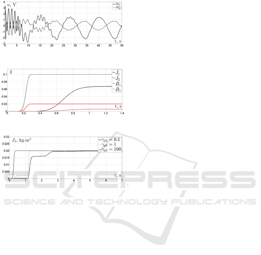
Figure 7: Intput signals used for the identification in the
closed-loop system.
Figure 8: Unknown parameters estimation results in the
closed-loop system.
Figure 9: Estimation results under different adaptation co-
efficients.
6 CONCLUSION
The paper resolves a parameter identification prob-
lem for a Twin Rotor MIMO System laboratory plat-
form. The DREM procedure is used for construct-
ing an identification algorithm and results are verified
by computer simulation. Unlike the analogues such
as classical gradient method, least squares method
or modern identification approaches such as (Do-
briborsci et al., 2019b), The DREM procedure en-
sures monotonic convergence even in case of multi-
ple related parameters simultaneously identification.
Graphics demonstrate the high accuracy of identifica-
tion and fast transients that can be improved by tuning
adaptation coefficients. Futher research will analyse
the DREM performance and applicability in the task
of parameter estimation of discrete systems.
ACKNOWLEDGEMENTS
This work was financially supported by Government
of Russian Federation (Grant 08-08). This work was
supported by the Ministry of Science and Higher Ed-
ucation of Russian Federation, goszadanie no. 2019-
0898.
REFERENCES
Aranovskiy, S., Bobtsov, A., Ortega, R., and Pyrkin, A.
(2016). Performance enhancement of parameter es-
timators via dynamic regressor extension and mixing.
volume 62, pages 3546–3550. IEEE.
Bazylev, D., Pyrkin, A., and Bobtsov, A. (2018a). Posi-
tion and speed observer for PMSM with unknown sta-
tor resistance. In 2018 European Control Conference
(ECC), pages 1613–1618. IEEE.
Bazylev, D., Vukosavic, S., Bobtsov, A., Pyrkin, A.,
Stankovic, A., and Ortega, R. (2018b). Sensorless
control of PM synchronous motors with a robust non-
linear observer. In 2018 IEEE Industrial Cyber-
Physical Systems (ICPS), pages 304–309. IEEE.
Bobtsov, A., Bazylev, D., Pyrkin, A., Aranovskiy, S., and
Ortega, R. (2017). A robust nonlinear position ob-
server for synchronous motors with relaxed excita-
tion conditions. International Journal of Control,
90(4):813–824.
Dobriborsci, D., Kolyubin, S., Karashaeva, F., and Bobtsov,
A. (2019a). Output adaptive switching controller de-
sign with DREM-based multi-harmonic disturbance
cancellation. volume 52, pages 263–268. Elsevier.
Dobriborsci, D., Margun, A., and Kolyubin, S. (2019b).
Tracking controller with harmonic disturbance cancel-
lation. In 2019 18th European Control Conference
(ECC), pages 1110–1115. IEEE.
Feedback Instruments, L. (1998). System advanced teach-
ing manual 1 (33-007-4m5). Feedback Instruments
Ltd, Crowborough, UK.
Feedback Instruments, L. (2006). Twin rotor MIMO sys-
tem control experiments 33-949s. Feedback Instru-
ments Ltd, Crowborough, UK.
Huang, L. (2011). An approach for robust control of a twin-
rotor multiple input multiple output system. In 2011
IEEE International Conference on Robotics and Au-
tomation, pages 4423–4428. IEEE.
Rahideh, A., Shaheed, M., and Huijberts, H. (2008). Dy-
namic modelling of a TRMS using analytical and
empirical approaches. Control Engineering Practice,
16(3):241–259.
Rahideh, A. and Shaheed, M. H. (2009). Robust model
predictive control of a twin rotor MIMO system. In
2009 IEEE International Conference on Mechatron-
ics, pages 1–6. IEEE.
ICINCO 2020 - 17th International Conference on Informatics in Control, Automation and Robotics
694
