
Real-time Implementation and Evaluation of Magnetometerless Tracking
System for Human and Humanoid Posture Control Benchmarking based
on Inertial Sensors
Vittorio Lippi
a
, Kai G
¨
unter Brands
b
and Thomas Seel
Technical University Berlin, Control Systems, Berlin, Germany
Keywords:
Tracking System, Magnetometerless, Humanoid Posture Control, Benchmarking.
Abstract:
This work describes a tracking system designed for humanoid robots, exoskeletons and humans oriented to
posture control and balance experiments. The system aims to provide a tool that allows for repeatability
of balance experiments across different robotics platforms and control algorithms with the ultimate aim of
providing a standardized framework for performance benchmarking. To make the system suitable for different
geometries and materials, it relies just on inertial sensors. The system is evaluated with a marker-based optical
tracking, performing a trial of a typical posture control and balance experiment. In particular the frequency
response function of the body segments respect to the support surface tilt is evaluated.
1 INTRODUCTION
Posture control and balance are fundamental com-
ponents of humanoid robot control, considering
the inherently unstable nature of humanoid body.
COMTEST is a sub-project of the EU project EU-
ROBENCH that aims to the development of a stan-
dardized testbed for balance performance (Lippi et al.,
2019b; Lippi et al., 2019a). In this framework, the
trajectory of body segments should be measured in a
repeatable way with different robots. In this work,
we evaluate a tracking system designed to be suit-
able for humans, robots, and exoskeletons regardless
of materials and geometry. The target of the pro-
posed solution are researchers and companies in the
field of humanoids and wearable robots. The track-
ing solution can be used at the EUROBENCH facility
or replicated in laboratories exploiting off-shelf track-
ing hardware. Posture control experiments have been
performed with optical tracking e.g. (Mergner et al.,
2009; Hettich et al., 2013; Hettich et al., 2015) or ex-
ploiting the same internal sensors used for the control
e.g. (Lippi, 2018; Ott et al., 2016; Hauser et al., 2011)
or a mixture of the two solutions e.g. (Zebenay et al.,
2015). Optical tracking is considered the golden stan-
dard for body tracking (Teufl et al., 2019b) and of-
ten the chosen solution for gait and posture analysis
a
https://orcid.org/0000-0001-5520-8974
b
https://orcid.org/0000-0003-0290-3257
Knee Joint 1 DoF
TS
LS
SS
FS
Gravitational
Vertical
B1 Orientation
(thigh)
B2 Orientation
(shank)
6D IMU Sensor
Figure 1: Placement of IMU sensors on Human/Humanoid
body and body segments kinematics. On the left: the posi-
tion of the 7 sensors on the body. Each sensor is fixed to a
body segment that is considered rigid. The joints between
segments are assumed to be 1 DoF hinge joints. The orien-
tation of each sensor respect to the tracked body segment is
not known a priori. On the right: the variables considered
for the analysis of posture control. The sway of body seg-
ments is expressed respect to the gravitational vertical (TS
= Trunk in space, LS= leg in space, SS = shank in space,
FS = foot in space). FS is expressed as the orientation of
the normal to the support surface, i.e. FS=0 means that the
surface is horizontal.
Lippi, V., Brands, K. and Seel, T.
Real-time Implementation and Evaluation of Magnetometerless Tracking System for Human and Humanoid Posture Control Benchmarking based on Inertial Sensors.
DOI: 10.5220/0009869106750680
In Proceedings of the 17th International Conference on Informatics in Control, Automation and Robotics (ICINCO 2020), pages 675-680
ISBN: 978-989-758-442-8
Copyright
c
2020 by SCITEPRESS – Science and Technology Publications, Lda. All rights reserved
675

(Leardini et al., 2005). Optical tracking systems have
the drawback of being expensive and limited by line-
of-sight restrictions. In recent years there has been
growing interest in developing cheaper body tracking
systems based on inertial measurements units, IMUs
(Miller et al., 2004; Fong and Chan, 2010; Buke et al.,
2015; Wong et al., 2015; Salehi. and Stricker., 2020).
IMUs typically require extensive calibration protocols
as well as a homogeneous magnetic field (De Vries
et al., 2009). The proposed tracking system will
use recently developed sensor fusion methods (Laidig
et al., 2017b; Seel and Ruppin, 2017) to achieve ac-
curate real-time motion tracking in a plug-and-play
manner (Laidig et al., 2017a; M
¨
uller et al., 2016; Seel
et al., 2014) without relying on a homogeneous mag-
netic field. This tracking system is meant to be a refer-
ence that can be used also to evaluate the internal sen-
sor fusion of the tested robot. The system specifica-
tions are designed to allow both the acquisition of the
data for offline analysis and also real time operations
and control, such as body-sway-referenced support
surface tilt (Mergner and Lippi, 2018) and provide po-
sition feedback to human subjects. In contrast to ex-
isting solutions, the magnetometer-free tracking sys-
tem is both real-time-capable and achieves automatic
sensor-to-segment calibration. In this work, the sys-
tem is evaluated using a marker-based optical tracking
system as reference, as done in previous works (Teufl
et al., 2019b; Naeemabadi. et al., 2018).
2 MATERIALS AND METHODS
2.1 Hardware
The proposed system uses wearable IMUs that are at-
tached to the body segments as shown in Fig. 1. The
hardware consists of a set of 7 Xsens MTw Awinda
units (Paulich et al., 2018), shown in Fig. 2 A. Data
from the accelerometer and gyroscope is captured at
a sampling frequency of 1000 Hz and low-pass fil-
tered at a bandwidth of 184 Hz. In this application
the movements are sampled at 100 Hz, with a latency
of 30 ms. The weight of each sensor is 16 g.
The optical tracking was performed with 9
Optitrack Flex 13 cameras at 120 Hz, data
were collected and analyzed with MotiveBody
(https://optitrack.com). A set of 5 reflective marker
was attached to each of the IMUs. The markers were
connected with a rigid structure shown in Fig. 2 B.
The support surface movement was implemented
with the 6 DOF device PS-6TM-150 from Motionsys-
tems (www.motionsystems.eu) controlled with a cus-
tom software. The support plate is 80×80 cm and the
Figure 2: Overview of the hardware components.(A) The
IMU. (B) The reflective markers. (C) A render of the mov-
ing support surface platform. On the left the 80×80 cm
support surface has been lifted to show the structure of the
moving platform.
subject is standing on its center. The 3D rendering of
the platform is shown in Fig. 2 C.
2.2 Tracking Algorithm
The algorithm used to track the lower limbs is sim-
ilar to the one presented in (Laidig et al., 2019) for
the tracking of human hands. The sensors are fixed
as shown in Fig 1. It is assumed that the joints are
move like a hinge joint following the work presented
in (Laidig et al., 2019) and (Laidig et al., 2017b). This
assumption is not true for the general range of motion
of human lower limbs, both because of multiple DoF
joints (e.g. the hip) and because of the elastic nature
of human tissues (that means that also the knee is not
strictly 1 DoF). Nevertheless this assumption is rea-
sonable in the context of the presented posture con-
trol experiment where body sway in the sagittal plane
is analyzed. Consider the tracking of two rigid bod-
ies, B
1
and B
2
, connected by a one-dimensional hinge
joint, like the thigh and the shank in the example in
Fig. 1, there is an IMU fixed to each rigid body, the
relative orientation of the IMUs is not known a priori.
The orientations are represented by the quaternions
B
1
E
1
q and
B
2
E
2
q where the subscript denotes the frame
of reference and the superscript denotes the frame of
interest. Due to the nature of the sensors, i.e. 6D
IMUs, the heading component of each orientation is
unknown. This is modeled as if the orientations are
estimated in the two reference frames E
1
and E
2
. As
only the heading is affected and the inclination can
ICINCO 2020 - 17th International Conference on Informatics in Control, Automation and Robotics
676

be correctly estimated by the accelerometer and gyro-
scope, the difference between E
1
and E
2
is only the
rotation
E
1
E
2
q(t,δ) around the global vertical axis. The
angle of this rotation is called heading offset and is de-
noted by δ(t)(Laidig et al., 2019). Knowing this angle
yields the relative orientation
B
1
B
2
q of the two bodies
with
B
2
B
1
q =
B
2
E
1
q
−1
⊗
E
2
E
1
q(t,δ) ⊗
B
2
E
2
q (1)
the basic idea to estimate the value of δ(t) is that
the relative orientation
B
1
B
2
q of a one-dimensional joint
is limited to rotations around one well-defined joint
axis, as shown in Fig.1 for the knee joint. Follow-
ing Eq. 1,the relative orientation can be formulated
as a function of δ(t) with
B
1
B
2
q = f (t, δ). It is then
possible to find an Euler angles decomposition of
B
2
B
1
q(t,δ)such that the first angle corresponds to the
joint angle (Laidig et al., 2019). The angles of the
decomposition are denoted by α,β and γ. Then the
following constraint holds:
|
β(t,δ)
|
+
|
γ(t,δ)
|
= 0 (2)
The heading offset δ(t) is a scalar variable that
can be estimated using a sliding window optimiza-
tion method based on the constraint 2 with the cost
function
e(δ) =
N
∑
k=1
β(t,δ)
2
+ γ(t,δ)
2
(3)
where t
k
being is sample index in a time-window with
N samples. This is computed repeatedly on overlap-
ping time windows to obtain the estimator
ˆ
δ(t) for the
heading offset. In the presented case the hip orienta-
tion,
H
q, is taken as reference and the corrected orien-
tations are computed applying Eq. 1 through the kine-
matic chains of the legs. The orientations of the right
thigh,
R T
q, and left thigh,
LT
q, given the respective
heading correction angles δ
{R |L}T
Eq. 1 becomes
{R |L}T
H
q =
H
E
1
q
−1
⊗
E
2
E
1
q(t,δ
{R |L}T
) ⊗
{R |L}T
E
2
q (4)
The calculated δ
{R |L}T
is used to correct the
thighs quaternions by rotating the reference frames of
the thighs, E
2
, onto the reference frame of the hip E
1
is
{R |L}T
E
1
q =
E
2
E
1
q(t,δ
{R |L}T
) ⊗
{R |L}T
E
2
q (5)
The same procedure is applied to the shank and
the foot segments.
2.3 Posture Control Analysis
The proposed tracking system aims to the develop-
ment of posture control experiments that allows the
comparison of human and robot responses (Torricelli
et al., 2020; Mergner and Lippi, 2018; Torricelli et al.,
2014). For this purpose the evaluation of the system
consist of a frequency domain analysis of the body
sway response induced by the external stimulus per-
formed in typical human and humanoid posture con-
trol experiments(Peterka, 2002; Mergner et al., 2009;
Mergner, 2010; Lippi and Mergner, 2017) . The sup-
port surface tilt profile is a pseudo-random ternary
sequence stimulus (PRTS), introduced by (Peterka,
2002). The signal profile is shown in Fig. 3. This
signal prevents humans and humanoids from using
prediction, that can affect strongly posture control
(Mart
´
ınez et al., 2014; Lippi, 2018). The power-
spectrum of the PRTS allows for the evaluation of
gain, phase, and coherence of the disturbance-evoked
body segments excursions (Mergner and Lippi, 2018).
The FRF is evaluated for COM sway (BS) and the
sway of specific body segments (LS,TS). BS is not
measured directly but computed from LS and TS as-
suming human body mass distribution from (Winter,
2009) as
BS = sin
−1
(m
T
l
L
+ m
L
h
L
)sin(LS) + h
T
m
T
sin(T S)
h
B
m
B
(6)
where m
T
is the mass of the trunk, m
L
the mass of
the legs and m
B
= m
T
+ m
L
the mass of the body ex-
cluding the feet. the mass distribution is defined by
the ratios m
T
/m
B
= 0.6982 and m
L
/m
B
= 0.3018 and
by the ratio between the height of the COM of the
respective segments, h
B
= 0.9684 for the whole body,
h
L
= 0.4753 for the leg and h
T
= 0.3173 for the trunk.
The leg length from ankle to hip was l
L
= 0.8642.
The FRFs are estimated transfer functions be-
tween the stimulus (FS) and the sway responses
(LS,TS,BS). The signals are transformed through dis-
crete Fourier transform, and the transfer function is
computed as the ratio between the cross-power spec-
trum of the input X and the output y and transform of
the input signal i.e.
H( f ) =
G
XY
( f )
G
X
( f )
(7)
Coherence is calculated as the squared cross-
power spectrum divided by the product of sway re-
sponse and stimulus power spectra. it varies from 0 to
1, where 0 indicates that there is no linear correlation
between the stimulus and response, and 1 represents a
perfect linear correlation. Both the presence of noise
and nonlinear relationships between input and output
Real-time Implementation and Evaluation of Magnetometerless Tracking System for Human and Humanoid Posture Control Benchmarking
based on Inertial Sensors
677

lead to coherence smaller than 1 (Bendat and Piersol,
2011).
The data are obtained through a single trial with
one subject (female, 30 years old, 176 cm tall) stand-
ing upright with eyes open on the platform. The study
was in accordance with the 1964 Helsinki Declaration
in its latest revision. Both the FRF (gain and phase)
and the coherence are computed and plotted over a set
of frequency of interest where the spectrum of PRTS
function has its peaks (see Fig.4).
3 RESULTS AND DISCUSSION
A comparison in time domain between the support
surface tilt and the foot orientation FS, that repre-
sent the last element in the kinematic chain is shown
in Fig. 3. There are some small tracking errors on
the absolute position, specifically a RMSE = 0.0094
◦
.
Most of the tracking error on FS is represented by
high frequency disturbance and appears to be con-
centrated on specific samples, e.g. around 150 s. A
comparison of the two signals in frequency domain is
shown in Fig. 4. The comparison confirms that the
most of the difference between the stimulus and the
tracked FS is represented by differences at higher fre-
quencies.
0 50 100 150 200 250 300 350
time [s]
-4
-2
0
2
4
6
angles [°]
left foot
FS from IMU
Stimulus
Figure 3: Support Surface tracking using the reconstruction
of left foot position. The stimulus is the PRTS used as refer-
ence for the platform, the foot rotation FS has been centered
around the rest value of 49
◦
so that an angle of 0
◦
means that
the support surface is horizontal.
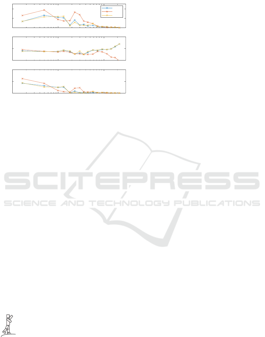
The frequency response functions describing the
sway of body segments, leg (LS) and trunk (TS), and
center of mass (BS) are shown in Fig. 5 in compari-
son with the same function obtained with the optical
tracking in Fig. 6. In this scenario the subject was not
using the knee joints and hence LS and SS are equiv-
alent. The two measures are in agreement over the
frequency of interests and exhibit some smaller dif-
ferences at higher frequencies, i.e. a difference can be
observed in the gain and the phase above 1 Hz. The
implication of Eq. 7 is that the power-spectrum of
the output at frequencies where the stimulus is zero is
10
-2
10
-1
10
0
0
0.5
1
1.5
2
Modulus[°s]
10
-2
10
-1
10
0
Freq (Hz)
-200
0
200
Phase [°]
FS from IMUs
Stimulus
frequencies of interest
Figure 4: Representation in frequency domain of the PRTS
profile (Stimulus, in orange) and the foot in space orienta-
tion tracked by the IMUs (FS, in blue). There is some track-
ing error, most of it not associated with the frequencies of
interest where the PRTS spectrum has its peaks.
not relevant. The FRF is computed and plotted only
for the frequencies where the PRTS spectrum is not
zero. This means that not all the error observed in
time domain, showed in Fig. 3, is reflected in the re-
sult showed in Fig. 5.
10
-2
10
-1
10
0
0
0.2
0.4
Output/Stim magitude
IMUs Tracking
BS
TS
LS=SS
10
-2
10
-1
10
0
-500
0
500
Output/Stim phase [°]
10
-2
10
-1
10
0
Freq (Hz)
0
0.5
1
Output/Stim Coherence
Figure 5: Frequency response functions (FRFs) body for
segments and body COM sway computed using the IMUs
tracking. The profile is similar to the one produced by op-
tical tracking (compare Fig. 6). The effect of measurament
noise is visible mainly at 1 Hz on LS and BS.
4 CONCLUSIONS AND FUTURE
WORK
The presented magnetometer-free tracking system
based on IMUs has been evaluated performing a trial
ICINCO 2020 - 17th International Conference on Informatics in Control, Automation and Robotics
678
10
-2
10
-1
10
0
0
0.2
0.4
Output/Stim magitude
Optical Tracking
BS
TS
LS=SS
10
-2
10
-1
10
0
-500
0
500
Output/Stim phase [°]
10
-2
10
-1
10
0
Freq (Hz)
0
0.5
1
Output/Stim Coherence
Figure 6: Frequency response functions (FRFs) body for
segments and body COM sway computed using the optical
tracking. Notice the absence of the small peak above 1 Hz
that can be observed in Fig. 5. Also the phase presents some
differences at higher frequencies.
and a typical frequency domain analysis required for
human and humanoid posture control experiments.
The system proved to be suitable for the analysis
of posture control experiments, in the sense that the
FRFs obtained for body segment sway were similar
to the ones obtained using optical tracking. Future
work will aim to the integration in the framework
of the EUROBENCH project,in order to use it for
other experiments proposed within the consortium. In
particular, the presented posture control analysis is
based on a reconstructed body position (TS,LS,BS).
For this purpose the system should be interchange-
able with other systems used within the consortium,
like wearHEALTH (Teufl et al., 2019b; Teufl et al.,
2019a), and allow for the comparison of experimental
results obtained with the different tracking systems.
The implementation of the system will be updated to
a sample rate of 100 Hz. During the developed of the
system, gait tracking was also tested. The analysis of
gait will be one possible additional use of the system
within the EUROBENCH consortium.
ACKNOWLEDGEMENTS
C
O
M
T
T
S
E
This work is supported by the project
COMTEST (Lippi et al., 2019b), a sub-
project of EUROBENCH (European Robotic
Framework for Bipedal Locomotion Bench-
marking, www.eurobench2020.eu) funded by
H2020 Topic ICT 27-2017 under grant agreement
number 779963. Thanks to Giorgio Castellano for the
3D render of the platform.
REFERENCES
Bendat, J. S. and Piersol, A. G. (2011). Random data: anal-
ysis and measurement procedures, volume 729. John
Wiley & Sons.
Buke, A., Gaoli, F., Yongcai, W., Lei, S., and Zhiqi, Y.
(2015). Healthcare algorithms by wearable inertial
sensors: a survey. China Communications, 12(4):1–
12.
De Vries, W., Veeger, H., Baten, C., and Van Der Helm, F.
(2009). Magnetic distortion in motion labs, implica-
tions for validating inertial magnetic sensors. Gait &
posture, 29(4):535–541.
Fong, D. T.-P. and Chan, Y.-Y. (2010). The use of wear-
able inertial motion sensors in human lower limb
biomechanics studies: a systematic review. Sensors,
10(12):11556–11565.
Hauser, H., Neumann, G., Ijspeert, A. J., and Maass, W.
(2011). Biologically inspired kinematic synergies en-
able linear balance control of a humanoid robot. Bio-
logical cybernetics, 104(4-5):235–249.
Hettich, G., Lippi, V., and Mergner, T. (2013). Human-like
sensor fusion mechanisms in a postural control robot.
In Londral, A. E., Encarnacao, P., and Pons, J. L.,
editors, Proceedings of the International Congress on
Neurotechnology, Electronics and Informatics. Vilam-
oura, Portugal, pages 152–160.
Hettich, G., Lippi, V., and Mergner, T. (2015). Human-like
sensor fusion implemented in the posture control of a
bipedal robot. In Neurotechnology, Electronics, and
Informatics, pages 29–45. Springer.
Laidig, D., Lehmann, D., B
´
egin, M.-A., and Seel, T.
(2019). Magnetometer-free realtime inertial motion
tracking by exploitation of kinematic constraints in 2-
dof joints. In 2019 41st Annual International Confer-
ence of the IEEE Engineering in Medicine and Biol-
ogy Society (EMBC), pages 1233–1238. IEEE.
Laidig, D., M
¨
uller, P., and Seel, T. (2017a). Auto-
matic anatomical calibration for imu-based elbow an-
gle measurement in disturbed magnetic fields. Current
directions in biomedical engineering, 3(2):167–170.
Laidig, D., Schauer, T., and Seel, T. (2017b). Exploiting
kinematic constraints to compensate magnetic distur-
bances when calculating joint angles of approximate
hinge joints from orientation estimates of inertial sen-
sors. In 2017 International Conference on Rehabilita-
tion Robotics (ICORR), pages 971–976. IEEE.
Leardini, A., Chiari, L., Croce, U. D., and Cappozzo, A.
(2005). Human movement analysis using stereopho-
togrammetry: Part 3. soft tissue artifact assessment
and compensation. Gait & Posture, 21(2):212 – 225.
Lippi, V. (2018). Prediction in the context of a human-
inspired posture control model. Robotics and Au-
tonomous Systems.
Lippi, V. and Mergner, T. (2017). Human-derived dis-
turbance estimation and compensation (dec) method
lends itself to a modular sensorimotor control in a hu-
manoid robot. Frontiers in neurorobotics, 11:49.
Lippi, V., Mergner, T., Seel, T., and Maurer, C. (2019a).
Benchmarking humanoid postural control–techniques
Real-time Implementation and Evaluation of Magnetometerless Tracking System for Human and Humanoid Posture Control Benchmarking
based on Inertial Sensors
679

and technologies inspired by human experiments. In
IEEE Humanoids Workshop on: performance indica-
tors and benchmarking facilities for bipedal locomo-
tion, IEEE-RAS 19th International Conference on Hu-
manoid Robots (Humanoids).
Lippi, V., Mergner, T., Seel, T., and Maurer, C. (2019b).
COMTEST project: A complete modular test stand
for human and humanoid posture control and bal-
ance. In 2019 IEEE-RAS 19th International Con-
ference on Humanoid Robots (Humanoids) Toronto,
Canada. October 15-17.
Mart
´
ınez, S., Esteban, D., Jard
´
on, A., and Balaguer, C.
(2014). Anticipative humanoid postural control sys-
tem for locomotive tasks. In 2014 IEEE-RAS Interna-
tional Conference on Humanoid Robots, pages 146–
151.
Mergner, T. (2010). A neurological view on reactive human
stance control. Annual Reviews in Control, 34(2):77–
198.
Mergner, T. and Lippi, V. (2018). Posture control human-
inspired approaches for humanoid robot benchmark-
ing: Conceptualizing tests, protocols and analyses.
Frontiers in Neurorobotics, 12:21.
Mergner, T., Schweigart, G., and Fennell, L. (2009).
Vestibular humanoid postural control. Journal of
Physiology - Paris, 103:178–194.
Miller, N., Jenkins, O. C., Kallmann, M., and Mataric, M. J.
(2004). Motion capture from inertial sensing for un-
tethered humanoid teleoperation. In 4th IEEE/RAS In-
ternational Conference on Humanoid Robots, 2004.,
volume 2, pages 547–565. IEEE.
M
¨
uller, P., B
´
egin, M.-A., Schauer, T., and Seel, T. (2016).
Alignment-free, self-calibrating elbow angles mea-
surement using inertial sensors. IEEE journal of
biomedical and health informatics, 21(2):312–319.
Naeemabadi., M., Dinesen., B., Andersen., O. K., Najafi.,
S., and Hansen., J. (2018). Evaluating accuracy and
usability of microsoft kinect sensors and wearable
sensor for tele knee rehabilitation after knee operation.
In Proceedings of the 11th International Joint Confer-
ence on Biomedical Engineering Systems and Tech-
nologies - Volume 1 BIODEVICES: BIODEVICES,,
pages 128–135. INSTICC, SciTePress.
Ott, C., Henze, B., Hettich, G., Seyde, T. N., Roa, M. A.,
Lippi, V., and Mergner, T. (2016). Good posture, good
balance: Comparison of bioinspired and model-based
approaches for posture control of humanoid robotsg.
IEEE Robotics & Automation Magazine, 23(1):22–33.
Paulich, M., Schepers, M., Rudigkeit, N., and Bellusci,
G. (2018). Xsens mtw awinda: Miniature wireless
inertial-magnetic motion tracker for highly accurate
3d kinematic applications. Xsens: Enschede, The
Netherlands.
Peterka, R. (2002). Sensorimotor integration in hu-
man postural control. Journal of neurophysiology,
88(3):1097–1118.
Salehi., S. and Stricker., D. (2020). Validation of a low-
cost inertial exercise tracker. In Proceedings of the
9th International Conference on Sensor Networks -
Volume 1: SENSORNETS,, pages 97–104. INSTICC,
SciTePress.
Seel, T., Raisch, J., and Schauer, T. (2014). Imu-based
joint angle measurement for gait analysis. Sensors,
14(4):6891–6909.
Seel, T. and Ruppin, S. (2017). Eliminating the effect
of magnetic disturbances on the inclination estimates
of inertial sensors. IFAC-PapersOnLine, 50(1):8798–
8803.
Teufl, W., Lorenz, M., Miezal, M., Taetz, B., Fr
¨
ohlich,
M., and Bleser, G. (2019a). Towards inertial sen-
sor based mobile gait analysis: Event-detection and
spatio-temporal parameters. Sensors, 19(1):38.
Teufl, W., Miezal, M., Taetz, B., Fr
¨
ohlich, M., and Bleser,
G. (2019b). Validity of inertial sensor based 3d joint
kinematics of static and dynamic sport and physiother-
apy specific movements. PloS one, 14(2).
Torricelli, D., Mizanoor, R. S., Gonzalez, J., Lippi, V., Het-
tich, G., Asslaender, L., Weckx, M., Vanderborght,
B., Dosen, S., Sartori, M., et al. (2014). Benchmark-
ing human-like posture and locomotion of humanoid
robots: A preliminary scheme. In Conference on
Biomimetic and Biohybrid Systems, pages 320–331.
Springer.
Torricelli, D., Mizanoor, R. S., Lippi, V., Weckx, M., Math-
ijssen, G., Vanderborght, B., Mergner, T., Lefeber, D.,
and Pons, J. L. (2020). Benchmarking human like-
ness of bipedal robot locomotion: State of the art and
future trends. In Metrics of Sensory Motor Coordi-
nation and Integration in Robots and Animals, pages
147–166. Springer.
Winter, D. A. (2009). Biomechanics and motor control of
human movement. John Wiley & Sons.
Wong, C., Zhang, Z.-Q., Lo, B., and Yang, G.-Z. (2015).
Wearable sensing for solid biomechanics: A review.
IEEE Sensors Journal, 15(5):2747–2760.
Zebenay, M., Lippi, V., and Mergener, T. (2015). Human-
like humanoid robot posture control. In 2015 12th
International Conference on Informatics in Control,
Automation and Robotics (ICINCO), volume 2, pages
304–309. INSTICC, SciTePress.
ICINCO 2020 - 17th International Conference on Informatics in Control, Automation and Robotics
680
