PD Sliding Mode Controller based Decoupled Aerial Manipulation
Kamel Bouzgou
1,2 a
, Laredj Benchikh
1 b
, Lydie Nouveliere
1 c
, Yasmina Bestaoui
1 d
and Zoubir Ahmed-Foitih
2 e
1
IBISC, Univ. Evry, Universit
´
e Paris-Saclay, 91025, Evry, France
2
LEPESA Laboratory, Faculty of Electrical Engineering, Department of Electronics, USTO-MB,31000 Oran, Algeria
Keywords:
Aerial Manipulation, Decoupled Dynamic System, SMC, Sliding Mode Control, PD-SMC.
Abstract:
This paper presents the design of 3-Dof multi-link robot arm that is mounted on the multirotor. To be consid-
ered the dynamic characteristics of the manipulation platform, the decoupled dynamic models of the system
are derived. The main advantage of the first joint is introduced for more robustness and stability during hover-
ing. The PID controller will be implemented for position and attitude of multirotor control, whereas, a sliding
mode controller will be designed for a manipulator robot, which is then compared with the sliding surface
that has been integrated with the proportional-derivative (PD) controller. The performance of the proposed
technique is demonstrated through a simulation using Simulink and Matlab environment.
1 INTRODUCTION
Unmanned aerial manipulators (UAMs) are used for
mobile manipulations thanks to their mobility which
enables a simple hovering to aggressive manoeuvr-
ers. It has emerged a need for the interaction of that
UAVs with the environment that is not easily acces-
sible by humans, for this aim, the researchers have
used this structure for transporting, manipulation and
grasping tasks. Moreover, the control of these aerial
manipulator is a very challenging problem, consider-
ing that such system is under-actuation and the cou-
pled dynamics between the two different platforms,
and the contact with the environment during manipu-
lation. Several survey papers deal with projects that
the multi-link robotic arm attached to the UAV for
manipulation tasks are used, the dynamic formalism
and control technique developed. Authors in (Bouz-
gou et al., 2019a) have classified aerial manipulator
systems based on aerial vehicles and the attached arm
kind. For the simple grasping task, a magnet attached
to the UAV is presented in (Escareno et al., 2014). A
single Dof to push an object in the desired direction,
in (Srikanth et al., 2011; Yeol et al., 2017) is designed
a
https://orcid.org/0000-0003-2374-2149
b
https://orcid.org/0000-0002-4617-399X
c
https://orcid.org/0000-0003-0027-7192
d
https://orcid.org/0000-0001-7716-5952
e
https://orcid.org/0000-0003-3121-9964
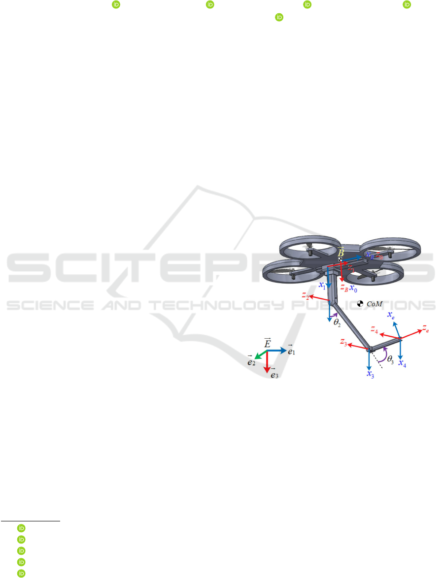
Figure 1: The structure of Q-PRR with principal frames.
as a non-prehensile manipulation and tentacle system.
The most structure of aerial manipulator arm is
when a 2-Dof robot arm iw mounted (Aydemir et al.,
2015; Kim et al., 2013), that number of dof can help
users to avoid a singularity region in the manipulator
arm workspace. A 3-Dof manipulator arm as revo-
lute joints is used in (Mello et al., 2015), when 4-Dof
multi-link manipulator arm is presented in (Jimenez-
Cano et al., 2017) as a serial robot placed at the up-
per part of the UAV for bridge inspection. In (Kon-
dak et al., 2013) authors are used a 5-Dof manipulator
robot for environment interaction. An industrial ma-
nipulator as a redundant robot arm with n > 6 is used
in (Huber et al., 2013) aerial manipulation with a 7-
Dof based on a main-tail-rotor helicopter, in (Danko
484
Bouzgou, K., Benchikh, L., Nouveliere, L., Bestaoui, Y. and Ahmed-Foitih, Z.
PD Sliding Mode Controller based Decoupled Aerial Manipulation.
DOI: 10.5220/0009856704840489
In Proceedings of the 17th International Conference on Informatics in Control, Automation and Robotics (ICINCO 2020), pages 484-489
ISBN: 978-989-758-442-8
Copyright
c
2020 by SCITEPRESS – Science and Technology Publications, Lda. All rights reserved

and Oh, 2014) the Hyper-redundant manipulator is
presented as 9-Dof for a wide reachable workspace.
A delta structure fixed on side of UAV was introduced
in (Fumagalli et al., 2014), when a parallel robot is
used in (Cho and Shim, 2017; Danko et al., 2015).
For an object interaction and manipulation applying
forces and torques, a dual 4-dof arm mounted on UAV
is presented in (Korpela et al., 2013).
Researchers in (Ruggiero et al., 2015), have de-
veloped a structure with a moving battery of the UAV
in one direction in order to hold the Multirotor CoG
as close as possible to the vertical axis, The drawback
of such structure is that battery movement is bounded
when the end-effector tried to reach the desired po-
sition and battery position cannot always ensure the
alignment of CoM of UAV and robot arm. A new
aerial manipulator with a 3-Dof is developed in this
paper (Bouzgou et al., 2019b), the alignment of CoG
of whole system can be ensured with a simple move-
ment of a prismatic joint along x-axis Figure 1. wide
workspace with this design and offering large possible
configurations of the robot arm for a desired position
and attitude without losing the optimum location of
the Q-PRR CoG (Bouzgou and Ahmed-Foitih, 2015).
An adaptive sliding controller based on a tradi-
tional Lagrange modeling method was proposed(Kim
et al., 2013), An augmented adaptive sliding con-
troller based on a closed-chain robot dynamics was
presented for cooperative transportation of multiple
(Lee et al., 2015) online estimation of objects based
on an augmented adaptive sliding controller was pro-
posed.
2 MODELING
The configuration of the proposed aerial manipulator
consists of two parts, the multi-rotor with the num-
ber of rotors that n
r
= 4 that can be called with the
letter ”Q” for Quadrotor more details see (Bouzgou
et al., 2019a), and the manipulator arm attached to the
bottom, whose geometric centers are considered to be
in the same z axis (
~
b
3
) of the mobile frame
~
B. The
manipulator consists of three degrees of freedom (3-
Dof), Prismatic-Revolute-Revolute joints, called (Q-
PRR), the first joint is prismatic and its axis (x
1
) is
parallel to the x-axis of the multirotor mobile frame
~
B, this joint is considered actuated and it moves along
the same axis, and it is bounded on both directions
by a value r
0
, the distance between two axes x
b
and
x
1
is denoted by (d
0
), The second and third joints are
revolute, their rotation axes (z
2
)and (z
3
)are parallel to
the (y) axis of the
~
B unit, where the manipulator arm
movements are considered in the (x, z)-axis of the
~
B
mobile frame. The position of the
~
B fixed frame with
respect to the
~
E inertial frame is given by the (3 × 1)
vector denoted by p
b
, whereas its orientation denoted
by R
b
is represented by the XY Z rotation sequence
with the fixed frame axes, and its orientation by the
fixed frame axes.
R
b
=
c
θ
c
ψ
s
φ
s
θ
c
ψ
− c
φ
s
ψ
c
φ
s
θ
c
ψ
+ s
φ
s
ψ
c
θ
s
ψ
s
φ
s
θ
s
ψ
+ c
φ
s
ψ
c
φ
s
θ
s
ψ
− s
φ
c
ψ
−s
θ
s
φ
c
θ
c
φ
c
θ
(1)
where s
∗
= sin(∗), c
∗
= cos(∗), Let R
b
e
be the orien-
tation matrix of the end-effector attached frame, and
p
b
e
=
x
eb
y
eb
z
eb
T
the position vector of the origin
with respect to
~
B fixed frame, and the absolute posi-
tion vector and orientation matrix of the end-effector
with respect to
~
E, is given by the p
e
=
x
e
y
e
z
e
T
and
R
e
, respectively, where the pair (p
b
,R
b
) ∈ SE(3) de-
notes the vector position given by p
b
=
x
b
y
b
z
b
T
,
and the orientation matrix of the multirotor with re-
spect to the inertial frame
~
E.
The position and orientation equations of end-
effector expressed in
~
E are written as follows:
p
e
= p
b
+ R
b
p
b
e
(2)
R
e
= R
b
.R
b
e
(3)
By denoting with
˙
ϕ
b
the time derivative of ϕ
b
.
ω
b
= T (φ
b
)
˙
ϕ
b
(4)
Where T (φ
b
) is the transformation matrix be-
tween the time derivative of the Euler angles ϕ
b
and
the angular velocity of the multirotor ω
b
.
T (φ
b
) =
1 0 −s
θ
0 c
φ
s
φ
c
θ
0 −s
φ
c
φ
c
θ
(5)
By differentiating (2), (3) and with taking into ac-
count (4), the translational and angular velocities of
the end-effector with respect to
~
E can be written as
follows:
˙p
e
= ˙p
b
− R
b
b
p
b
eb
T (φ
b
)
˙
ϕ
b
+ R
b
˙p
b
eb
(6)
ω
e
= T (φ
b
)
˙
ϕ
b
+ R
b
ω
b
eb
(7)
Where ˙p
b
,ω
b
are the linear and angular velocities
of the mobile frame
~
B with respect to the
~
E frame,
respectively, and ˙p
b
eb
,ω
b
eb
are the translational and an-
gular velocities of the end-effector with respect to the
mobile frame
~
B. (ˆ.), the hat map that transforms a
vector in R
3
to (3 × 3) Skew-symmetric matrix such
that ˆxy = x × y, ∀x, y ∈ R
3
(Kamel et al., 2017).
The dynamic model of Q-PRR can be derived by
considering the Lagrange formulation in details in
(Lippiello and Ruggiero, 2012). The function of La-
grangian is then expressed by L = E − U where E ,
PD Sliding Mode Controller based Decoupled Aerial Manipulation
485

U denote the kinematics and potential energy of the
whole system, respectively. The Lagrange equations
are given by
d
dt
δL
δ
˙
ξ
i
−
δL
δξ
i
= u + u
ext
(8)
Where i = 1, ..., 6 + n is the i − th coordinate of ξ,
and u
i
is the ((6 +n)×1) vector of generalized forces
and torques, and u
ext
denotes the vector of external
disturbance forces and torques. the dynamic model of
the global system can be written as
B(ξ)
¨
ξ +C(ξ,
˙
ξ)
˙
ξ + G(ξ) = u + u
ext
(9)
Where G is a ((6 + n) × 1) vector of gravitational
terms given by deriving the potential energy as
G(ξ) =
δP
δξ
And C is the matrix of Coriolis and cen-
trifugal terms. more details see (Bouzgou et al.,
2019b).
u
i
is the vector of generalized forces at the i-th
joint level. τ
b
is the vector of torques composed with
τ
φ
, τ
θ
and τ
ψ
generated by the system computed
around x,y and z axes respectively. Let µ be the vector
of the force f
r
0
applied to the prismatic joint and τ
θ
2
,
τ
θ
3
torques applied by the revolute joint of the robot
arm.
u =
u
f
b
u
τ
b
u
µ
=
R
b
f
b
R
T
b
T
b
τ
b
µ
=diag(R
b
,Q, I
n
)
f
b
=
0
0
f
bz
, τ
b
=
τ
φ
τ
θ
τ
ψ
, µ =
f
r
0
τ
θ
2
τ
θ
3
f
bz
τ
b
=
1 1 1 1
0 l 0 −l
−l 0 l 0
c −c c −c
f
1
f
2
f
3
f
4
(10)
Where l is the distance from each motor to the mul-
tirotor centre of mass. When c is the drag factor.
Since B(ξ
i
) is symmetric B
i j
= B
T
ji
, and Let the ma-
trices M
pp
, M
pϕ
, M pq, M
ϕϕ
, M
ϕq
, M
qq
be defined
by partitioning the mass matrix and by according to
the equation defined in Equation 9 the decoupled dy-
namic model for the overall system is presented and a
sub-matrices are given from that equation and can be
rewrite as follows
B(ξ
i
) =
B
pp
B
pϕ
B
pq
B
T
pϕ
B
ϕϕ
B
ϕq
B
T
pq
B
T
ϕq
B
qq
(11)
C(ξ,
˙
ξ) =
C
p
C
ϕ
C
q
, G(ξ
i
) =
G
p
G
ϕ
G
q
The dynamic modeling of the decoupled system is
presented as follows For the multirotor, a new coordi-
nate joint can be defined as a part of the generalized
coordinates xi
i
such that q
m
=
p
b
ϕ
b
T
. Multirotor
motion equations Equations to respect the Lagrange
formalism in Equation 9 and the decomposition of the
B,C and G matrices can be defined as follows
B
pp
¨p
b
+ B
pϕ
¨
ϕ
b
+C
p
˙p
b
+ G
p
+ B
pq
¨q
eb
= u
f
b
(12)
B
T
pϕ
¨p
b
+ B
ϕϕ
¨
ϕ
b
+C
ϕ
˙
ϕ
b
+ G
ϕ
+ B
ϕq
¨q
eb
= u
τ
b
(13)
B
T
pq
¨p
b
+ B
T
ϕq
¨
ϕ
b
+C
q
˙q
eb
+ G
q
+ B
qq
¨q
eb
= u
µ
(14)
From the equation 12 and 13, the dynamic model
can be simplified with taking into account the de-
coupled terms. Rewrite that with the model defined
in (Kamel et al., 2017), where M
p
= B
pq
¨q
eb
, M
ϕ
=
B
ϕq
¨q
eb
and M
q
= B
T
pq
¨p
b
+ B
T
ϕq
¨
ϕ
b
∈ R
3×1
, such as
M
p
=
M
x
M
y
M
z
and M
ϕ
b
=
M
φ
M
θ
M
ψ
.
Equations becomes as
m ¨x = (c
φ
s
θ
c
ψ
+ s
φ
s
ψ
)u
1
− M
x
(15)
m ¨y = (c
φ
s
θ
s
ψ
− s
φ
c
ψ
)u
1
− M
y
(16)
m¨z = (c
φ
c
θ
)u
1
− mg − M
z
(17)
I
x
¨
φ =
˙
θ
˙
ψ(I
y
− I
z
) − J
r
˙
θΩ
r
+ lu
2
− M
φ
(18)
I
y
¨
θ =
˙
φ
˙
ψ(I
z
− I
x
) − J
r
˙
ψΩ
r
+ lu
3
− M
θ
(19)
I
z
¨
ψ =
˙
φ
˙
θ(I
x
− I
y
) + u
4
− M
ψ
(20)
where, Ω
r
= (ω
2
+ ω
4
− ω
1
− ω
3
), I
x
, I
y
, I
z
are
the inertia matrix terms and m the multirotor mass.
The dynamic modeling of the robot arm is defined
using a Lagrange Formalism depicted in Equation
9, where the jacobians matrix are defined by using
a Denavit-Hartenberg method depicted in (Bouzgou
and Ahmed-Foitih, 2014)and its equation of move-
ment can be presented as follow
f
r
0
= (m
1
+ m
2
+ m
3
)¨r
0
+
1
2
m
3
(
1
2
d
3
c
θ
2
+θ
3
+ d
2
c
θ
2
) + d
2
m
2
c
θ
2
¨
θ
2
+
1
2
(d
3
m
3
c
θ
2
+θ
3
)
¨
θ
3
−
1
2
2m
3
(
1
2
d
3
s
θ
2
+θ
3
+ d
2
s
θ
2
) + d
2
m
2
s
θ
2
˙
θ
2
2
−
1
2
d
3
m
3
s
θ
2
+θ
3
˙
θ
2
3
− d
3
m
3
s
θ
2
+θ
3
˙
θ
2
˙
θ
3
− g(m
1
+ m
2
+ m
3
) (21)
ICINCO 2020 - 17th International Conference on Informatics in Control, Automation and Robotics
486
τ
θ
2
= (m
3
(
1
2
d
3
c
θ
2
+θ
3
+ d
2
c
θ
2
) +
1
2
d
2
m
2
c
θ
2
)¨r
0
+
I
y3
+ I
z2
+
1
2
m
2
d
2
2
+ d
2
2
m
3
+
1
4
m
3
d
2
3
+ d
2
d
3
m
3
c
θ
3
¨
θ
2
+
1
4
m
3
d
2
3
+
1
2
d
2
d
3
m
3
c
(θ
3
)
+ I
y3
˙
θ
3
−
1
2
(I
x3
s
2θ
2
+2θ
3
− I
z3
s
2θ
2
+2θ
3
+ d
2
d
3
m
3
s
θ
3
)
˙
θ
2
3
− d
2
d
3
m
3
s
θ
3
˙
θ
2
˙
θ
3
− g
m
3
(
1
2
d
3
c
θ
2
+θ
3
+ d
2
c
θ
2
) +
1
2
d
2
m
2
c
θ
2
(22)
τ
θ
3
=
1
2
d
3
m
3
c
θ
2
+θ
3
¨r
0
+
I
y3
+
1
4
m
3
d
2
3
+
1
2
d
2
d
3
m
3
c
θ
3
¨
θ
2
+
I
y3
+ I
z3
+
1
4
m
3
d
2
3
+ I
x3
s
2
θ
2
+θ
3
− I
z3
s
2
θ
2
+θ
3
¨
θ
3
+
1
2
d
2
d
3
m
3
s
(θ
3
˙
θ
2
2
+
1
2
2I
x3
c
θ
2
+θ
3
s
θ
2
+θ
3
− 2I
z3
c
θ
2
+θ
3
s
θ
2
+θ
3
˙
θ
2
3
+ s
2θ
2
+2θ
3
(I
x3
− I
z3
)
˙
θ
2
˙
θ
3
−
1
2
d
3
gm
3
c
θ
2
+θ
3
(23)
Where, c
∗
= cos(∗),s
∗
= sin(∗). These equations can
be rewritten as a matrix forms regarding to the Equa-
tion 14.
3 CONTROL DESIGN
This section describes the design of the controller for
the decoupled system, it is composed into three parts,
attitude control of the multirotor as a function of the
position of the desired center of gravity; and con-
trol of the manipulator arm when the system reaches
the target position point, the PID proportional integral
derivative controller is used for the multirotor and the
sliding mode technique for the manipulator arm and
then it will be improve when the PID will be added
in parallel. Figure 2 shows the diagram of the control
strategy.
From the dynamic equations , we have a de-
coupled system where the translational accelerations
don’t depend on angular acceleration, from the first
three equations we can extract the pitch and roll an-
gles when we introduce the desired position and atti-
tude. From equations 15, 16, 17, θ and φ can be com-
puted and its depended on multirotor position vector
Figure 2: Diagram of the control strategy.
and altitude
x y z ψ
, therefore, it can be writing as
follows
tan(θ) =
¨x +
M
x
m
c
ψ
+
¨y +
M
y
m
s
ψ
¨z + g +
M
z
m
(24)
sin(φ) =
¨x +
M
x
m
s
ψ
+
¨y +
M
y
m
c
ψ
r
¨x +
M
x
m
2
+
¨y +
M
y
m
2
+
¨z + g +
M
z
m
2
(25)
When the reference value for the roll and pitch an-
gles has been calculated, the control inputs of those
angles can be determined, and the feedback of the
speed time derivative will be required to determine
the input vector, in the continuous time,the parallel
PID controller is defined, it have a following form
u(t) = K
pζ
e(t) + K
iζ
Z
t
0
e(τ)dτ + K
dζ
de(t)
dt
(26)
ζ is the variable to be controlled. ζ ∈ {x, y, z, φ, θ, ψ}
Where,e(t) = ζ
d
− ζ, is the error between the desired
and measured value of ζ and K
pζ
, K
iζ
are Proportional
and Integral gain,respectively.
3.1 Manipulator Arm Controller
For the manipulator arm, sliding mode control strat-
egy will be presented, the main idea of this approach
can be presented as follows.
Considering the non-linear n-order object defined
as
x
(n)
(t) = f (x,t) + u(t) (27)
where x is the state variable,u is the control law. Let
be e is the error between desired and measured value
of x, such as e = x
des
− x, let be s = 0 as a sliding
surface defined by
s = e
(n−1)
+ λ
1
.e
(n−2)
+ ... + λ
n−2
˙e + λ
n−1
.e (28)
Where λ is the coefficient of the sliding surface.
Derivative the equation 28, it can write
˙s = e
n
+ λ
1
.e
(n−1)
+ ... + λ
n−2
.e
2
+ λ
n−1
. ˙e (29)
Using Equation 27 and with choosing the input con-
trol vector u that ˙s = Ksgn(s) with K is positive de-
fined. Substituting into Equation 29, the following
PD Sliding Mode Controller based Decoupled Aerial Manipulation
487
equation can be rewritten
u = − f (x,t)+x
(n)
des
+λ
1
.e
(n−1)
+...+λ
n−1
. ˙e+Ksgn(s)
(30)
sgn is the sign function, applying equation 30 with
n = 2 and for three link robot arm ¨x = f (x,t) + u(t).
The input control law is as follows
u(t) = − f (x,t) + q
des
+ λ. ˙e + Ksgn(s) (31)
With q
des
=
r
0,des
θ
2,des
θ
3,des
T
, λ =
λ
1
λ
2
λ
3
T
and K =
K
1
K
2
K
3
T
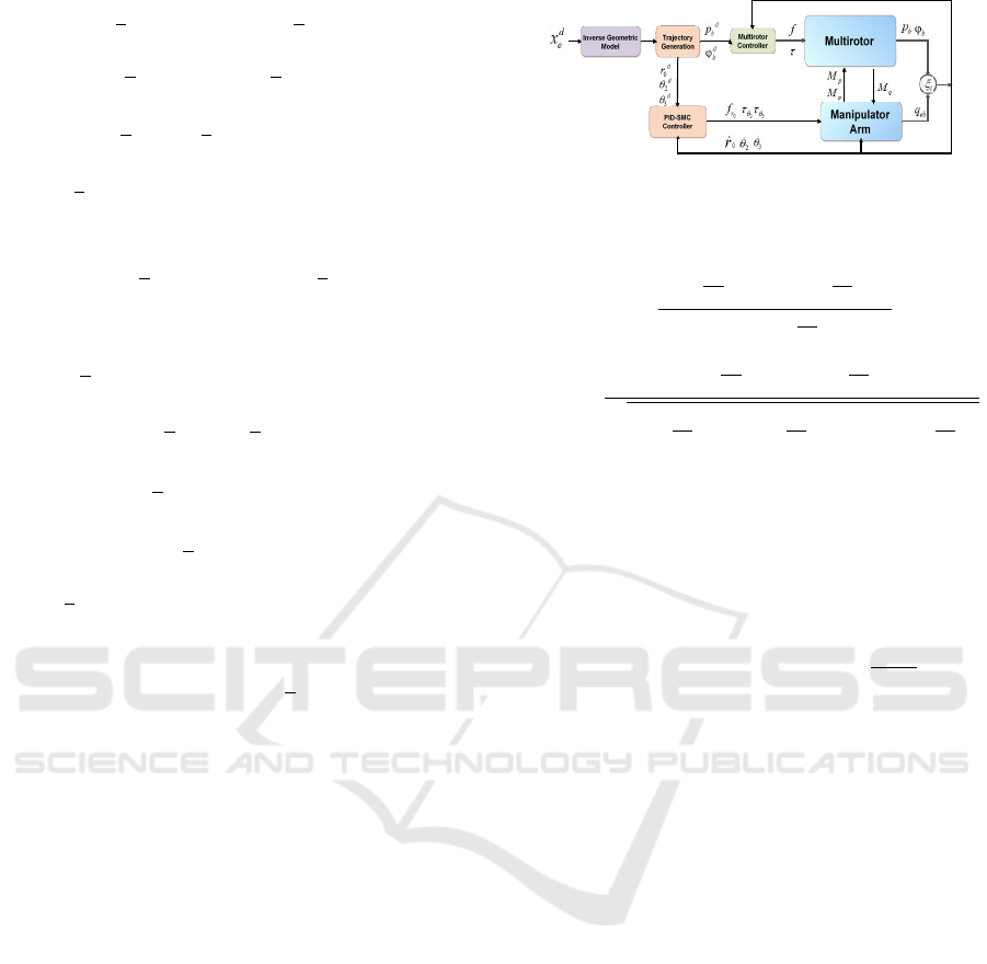
4 SIMULATION AND RESULTS
Simulations were conducted to evaluate the perfor-
mance of the aerial manipulator in maintaining an
end-effector position relative to fixed targets. the de-
sired position of the multirotor is given by p
b
[m] =
20 30 10
T
, and when the roll and pitch angles of the
multirotor are considering as zero, the movement of
the arm will be started, and the desired trajectory of all
joints is given by p
eb
=
0.04 0.6 0.2
T
[m,rad,rad]
The simulation results are summarized in Figure 3.
(a) (b)
Figure 3: Position of the multirotor centre of gravity in Fig-
ure 3a, the orientation of the multirotor fixed frame
~
B to
respect to the reference frame
~
E in the Figure 3b.
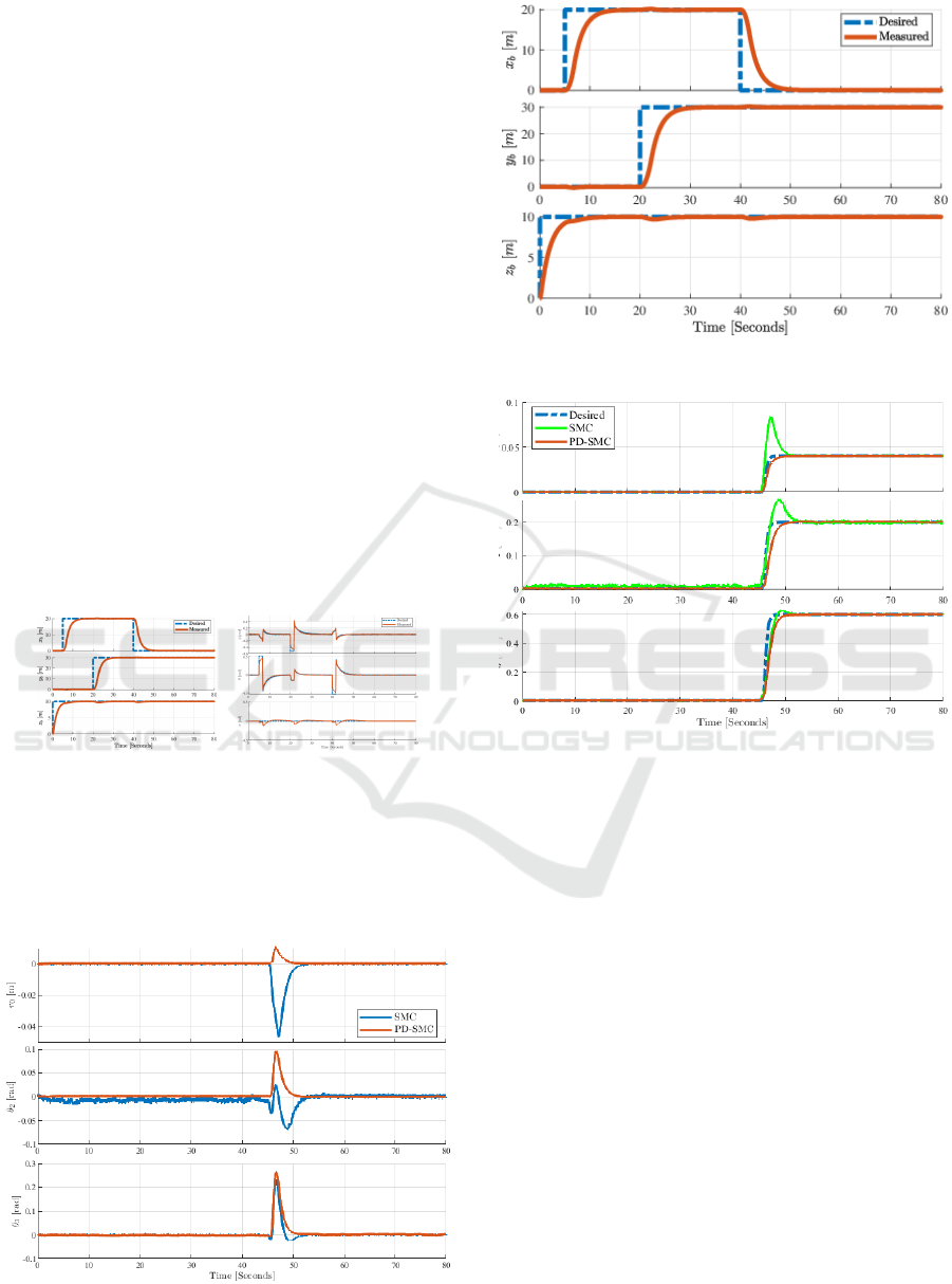
The position errors of the end-effector can be sum-
marized in the Figure 4.
Figure 4: Position Errors of the CoM of Q-PRR.
Figure 5: Position of the Center of mass of the Q-PRR.
Figure 6: Response of manipulator joints.
5 CONCLUSIONS
In this paper, a mathematical model for a decoupled
system (multirotor and robot arm) is presented by us-
ing the Denavit-Hartenberg approach for geometric
modeling of a manipulator arm, and a Lagrange For-
malism for dynamic modeling of both a Multirotor
and arm . The system dynamics is decoupled in two
separate subsystems, one concerning the position of
the center of mass where a PID controller is used to
keep a stability of the whole system during hovering,
a second subsystem concerning the attitude of the ma-
nipulator arm, which the sliding mode controller is
used to control each link for a path trajectory between
a start point to a desired position of the end-effector.
That controller is modified and PD terms are added
for the sliding mode blocs in order to improve the out-
put signal and defined good stability of the Q-PRR.
Simulation works are presented which validate and
show the efficiency of the proposed approach. Future
works will present an another approach for a dynamic
ICINCO 2020 - 17th International Conference on Informatics in Control, Automation and Robotics
488

model by using a SimMechanics and VRML environ-
ment (Bouzgou et al., 2014) (Bouzgou et al., 2015).
REFERENCES
Aydemir, M., Arıkan, K. B., and
˙
Irfano
˘
glu, B. (2015). Dis-
turbance rejection control of a quadrotor equipped
with a 2 dof manipulator. In Machine Vision and
Mechatronics in Practice, pages 91–103. Springer.
Bouzgou, K. and Ahmed-Foitih, Z. (2014). Geometric mod-
eling and singularity of 6 dof fanuc 200ic robot. In
Innovative Computing Technology (INTECH), 2014
Fourth International Conference on, pages 208–214.
IEEE.
Bouzgou, K. and Ahmed-Foitih, Z. (2015). Workspace
analysis and geometric modeling of 6 dof fanuc 200ic
robot. Procedia-Social and Behavioral Sciences,
182:703–709.
Bouzgou, K., Ahmed-Foitih, Z., and Oran-Algeria, U. M.
(2014). Singularity analysis and illustration of inverse
kinematic solutions of 6 dof fanuc 200ic robot in vir-
tual environment. Journal of Intelligent Computing,
5(3):91–105.
Bouzgou, K., Amar, R. H. E., and Ahmed-Foitih, Z. (2015).
Virtual reality simulation and singularity analysis of
3-rrr translational parallel robot. In Innovative Com-
puting Technology (INTECH), 2015 Fifth Interna-
tional Conference on, pages 61–66. IEEE.
Bouzgou, K., Benchikh, L., Nouveliere, L., Bestaoui, Y.,
and Ahmed-Foitih, Z. (2019a). A new classification
and aerial manipulation q-prr design.
Bouzgou, K., Benchikh, L., Nouveliere, L., Bestaoui, Y.,
and Ahmed-Foitih, Z. (2019b). A novel aerial manip-
ulation design, modelling and control for geometric
com compensation.
Cho, S. and Shim, D. H. (2017). Development of a vision-
enabled aerial manipulator using a parallel robot.
Transaction of the Japan Society for Aeronautical and
Space Sciences, 15(APISAT-2016):a27–a36.
Danko, T. W., Chaney, K. P., and Oh, P. Y. (2015). A parallel
manipulator for mobile manipulating uavs. In Tech-
nologies for Practical Robot Applications (TePRA),
2015 IEEE International Conference on, pages 1–6.
IEEE.
Danko, T. W. and Oh, P. Y. (2014). Design and control of
a hyper-redundant manipulator for mobile manipulat-
ing unmanned aerial vehicles. Journal of Intelligent &
Robotic Systems, 73(1-4):709.
Escareno, J., Flores, G., Rakotondrabe, M., Romero, H.,
Lozano, R., and Rubio, E. (2014). Task-based con-
trol of a multirotor miniature aerial vehicle having an
onboard manipulator. In Unmanned Aircraft Systems
(ICUAS), 2014 International Conference on, pages
857–863. IEEE.
Fumagalli, M., Naldi, R., Macchelli, A., Forte, F., Keemink,
A. Q., Stramigioli, S., Carloni, R., and Marconi,
L. (2014). Developing an aerial manipulator proto-
type: Physical interaction with the environment. IEEE
robotics & automation magazine, 21(3):41–50.
Huber, F., Kondak, K., Krieger, K., Sommer, D.,
Schwarzbach, M., Laiacker, M., Kossyk, I., Parusel,
S., Haddadin, S., and Albu-Sch
¨
affer, A. (2013). First
analysis and experiments in aerial manipulation us-
ing fully actuated redundant robot arm. In Intelligent
Robots and Systems (IROS), 2013 IEEE/RSJ Interna-
tional Conference on, pages 3452–3457. IEEE.
Jimenez-Cano, A., Heredia, G., and Ollero, A. (2017).
Aerial manipulator with a compliant arm for bridge
inspection. In Unmanned Aircraft Systems (ICUAS),
2017 International Conference on, pages 1217–1222.
IEEE.
Kamel, B., Yasmina, B., Laredj, B., Benaoumeur, I., and
Zoubir, A.-F. (2017). Dynamic modeling, simulation
and pid controller of unmanned aerial vehicle uav. In
Innovative Computing Technology(INTECH) Seventh
International Conference on, pages 64–69. IEEE.
Kim, S., Choi, S., and Kim, H. J. (2013). Aerial manipu-
lation using a quadrotor with a two dof robotic arm.
In Intelligent Robots and Systems (IROS)/RSJ Inter-
national Conference on, pages 4990–4995. IEEE.
Kondak, K., Krieger, K., Albu-Schaeffer, A., Schwarzbach,
M., Laiacker, M., Maza, I., Rodriguez-Castano, A.,
and Ollero, A. (2013). Closed-loop behavior of an
autonomous helicopter equipped with a robotic arm
for aerial manipulation tasks. International Journal of
Advanced Robotic Systems, 10(2):145.
Korpela, C., Orsag, M., Pekala, M., and Oh, P. (2013). Dy-
namic stability of a mobile manipulating unmanned
aerial vehicle. In germany 2013, I., editor, Robotics
and Automation International Conference on, pages
4922–4927. IEEE.
Lee, H., Kim, H., and Kim, H. J. (2015). Path planning and
control of multiple aerial manipulators for a cooper-
ative transportation. In 2015 IEEE/RSJ International
Conference on Intelligent Robots and Systems (IROS),
pages 2386–2391. IEEE.
Lippiello, V. and Ruggiero, F. (2012). Cartesian impedance
control of a uav with a robotic arm. IFAC Proceedings
Volumes, 45(22):704–709.
Mello, L. S., Aldorno, B., and Raffo, G. V. (2015). Whole-
body modeling and control of an unmanned aerial ma-
nipulator. In the XII Brazilian Symposium of Intelli-
gent Automation (XII SBAI). Natal.
Ruggiero, F., Trujillo, M. A., and all (2015). A multi-
layer control for multirotor uavs equipped with a servo
robot arm. In Robotics and Automation (ICRA),IEEE
International Conference on, pages 4014–4020.
Srikanth, M. B., Soto, A., Annaswamy, A., Lavretsky, E.,
and Slotine, J.-J. (2011). Controlled manipulation
with multiple quadrotors. In AIAA Conf. on Guidance,
Navigation and Control.
Yeol, J. W., Toohey, D., and Hwang, Y.-W. (2017). Design
and analysis of a multiple tentacle system for mobile
manipulation in micro aerial vehicles. Procedia Com-
puter Science, 105:7–13.
PD Sliding Mode Controller based Decoupled Aerial Manipulation
489
