
On the Improvement of R-TNCESs Verification using Distributed
Cloud-based Architecture
Choucha Chams Eddine
1
, Mohamed Oussama Ben Salem
2
, Mohamed Khalgui
1,3
, Laid Kahloul
4
and Naima Souad Ougouti
5
1
LISI Laboratory, National Institute of Applied Sciences and Technology (INSAT),
University of Carthage, Tunis 1080, Tunisia
2
Team Project IMAGES-ESPACE-Dev, UMR 228 EspaceDev IRD UA UM UG UR, University of Perpignan Via Domitia,
Perpignan 66860, France
3
School of Electrical and Information Engineering, Jinan University, Zhuhai Campus, Zhuhai 519070, China
4
LINFI Laboratory, Computer Science Department, Biskra University, Biskra, Algeria
5
LSSD Laboratory, Computer Science Department,
University of Science and Technology of Oran Mohamd Boudiaf, Algeria
Keywords:
Formal Verification, Discrete-event System, Reconfiguration, Petri Net, Ontology.
Abstract:
Reconfigurable discrete event control systems (RDECSs) are complex and critical systems, motivating the
use of formal verification. This verification consists of two major steps: state space generation and state
space analysis. The application of the mentioned steps is usually expensive in terms of computation time and
memory. This paper deals with state space generation (accessibility graph generation) during verification of
RDECSs modeled with specified reconfigurable timed net condition/event systems (R-TNCESs). We aim to
improve model checking used for formal verification of RDECSs by proposing a new aproach of state space
generation that considers similarities. In this approach, we introduce the modularity concept for verifying
systems by constructing incrementally their accessibility graphs. Furthermore, we set up an ontology-based
history to deal with similarities between two or several systems by reusing state spaces of similar components
that are computed during previous verification. A distributed cloud-based architecture is proposed to perform
the parallel computation for control verification time and memory occupation. The paper’s contribution is
applied to a benchmark production system. The evaluation of the proposed approach is performed by measur-
ing the temporal complexity of several large scale system verification. The results show the relevance of this
approach.
1 INTRODUCTION
Reconfigurable discrete event control systems
(RDECSs) are the trend of future systems. RDECSs
can be reconfigured in a static way (off-line) or in
a dynamic way (automatically at run-time). In the
latter, a reconfiguration scenario should be applied
automatically and timely as a response related to dy-
namic environment, or user requirements. Therefore,
an RDECS may go through several modes at run-time
(Khalgui et al., 2011), increasing verification process
complexity. Formal verification represents a reli-
able method to ensure the correctness of RDECSs.
Usually, it consists in generating and analyzing the
state spaces of studied systems. However, with the
combinatorial growth, the state space size becomes
too big, even with small sized systems. Hence,
model-checking becomes quite challenging for
industry and academia because of the state space
explosion problem (Valmari, 1996). Several studies
have been done to cope with state space explosion
problems. The authors in (Souri et al., 2019) present
symbolic model checking that represents the state
space symbolically instead of explicitly, by exploiting
the state graph regularity using boolean functions.
In (Gadelha et al., 2017), bounded model checking
(BMC) is proposed to look for a counter-example in
executions whose length is limited by an integer k. If
no bug is found, then k is increased until a possible
bug is found. The above methods can proceed
efficiently proceed to complex systems verification.
However, they use an implicit representation of state
Eddine, C., Ben Salem, M., Khalgui, M., Kahloul, L. and Ougouti, N.
On the Improvement of R-TNCESs Verification using Distributed Cloud-based Architecture.
DOI: 10.5220/0009836103390349
In Proceedings of the 15th International Conference on Software Technologies (ICSOFT 2020), pages 339-349
ISBN: 978-989-758-443-5
Copyright
c
2020 by SCITEPRESS – Science and Technology Publications, Lda. All rights reserved
339

spaces, which present limitation for computation of
quantitative properties (e.g., state probabilities in
stochastic models) (Camilli et al., 2014).
With the apparition of new complex systems such
as reconfigurable manufacturing systems, reconfig-
urable wireless networks, etc (Ben Salem et al.,
2017), techniques and formalisms used for verifica-
tion must evolve. Petri nets has been extended by
many works. Reconfigurable Petri nets presented in
(Padberg and Kahloul, 2018), proposed for reconfig-
urable systems. However, although useful, being non-
modular formalism, it can cause confusion to engi-
neers for possible reusing. Timed net condition/event
systems (TNCES) formalism prersented in (Hafidi
et al., 2018) as modular extension of Petri nets to deal
with time constraints. TNCES is used for their partic-
ular dynamic behavior, modularity and interconnec-
tion via signals. However, dynamic behavior of re-
configurable systems is still not supported. Reconfig-
urable net condition/event systems (R-TNCESs) are
developed as an extension of the TNCES formalism in
(Zhang et al., 2013), where reconfiguration and time
properties with modular specification are provided in
the same formalism while keeping the same seman-
tics of TNCESs. With R-TNCES formalism, physi-
cal system processes are easily understood thanks to
modular graphic representations. In addition, it can
capture complex characteristics of an RDECS. For-
mally an R-TNCES is a multi-TNCES defined as a
couple (B,R), where B is a set of TNCESs, and R is
a set of reconfiguration rules(Zhang et al., 2013). A
layer-by-layer verification method is proposed where
similarities between TNCESs are considered. This
method is improved in (Hafidi et al., 2018) where
the authors propose a new method for accessibil-
ity graph generation with less computing time and
less required memory.The previous methods improve
classical ones. However, with large scale systems,
their application using a unique machine (i.e., a cen-
tralized system) may be expensive in terms of time.
In this paper, we are interested in reconfigurable
systems, modeled with the R-TNCES formalism
where the RDECS behavior is represented by the be-
havior of control components (CCs) and the com-
munication between them (synchronization) (Zhang
et al., 2013). We propose a new verification method
that aims to improve R-TNCES formal verification.
Indeed, state space generation is considered the most
complex verification step, thus we focus on its im-
provement. The verification of an R-TNCES requires
checking of each configuration, namely each TNCES.
TNCESs which describe configurations often contain
similarities called internal similarities. On another
hand, some RDECSs share the same system compo-
nents, so their model contains similarities called ex-
ternal similarities, which implies redundant calcula-
tion during checking of these systems. Thus, in order
to avoid many repetitive computation due to previous
problems, we propose in this paper the following con-
tributions:
1. An ontology-based history to facilitate the de-
tection of external similarities: Ontologies allow
us to describe the RDECSs (components, work
process, component relationships ..., etc.) in an
abstracted way than the formal model. Thus,
we can efficiently detect the similarities between
RDECSs with less computing time and resources,
thank the ontology alignment method (Ougouti
et al., 2017). Each model must be accompanied by
a system ontology, which describes the system to
be verified. The system ontology is aligned to the
ontology-based history, which contains descrip-
tions of already verified systems. The detected
similarities allow reusing state spaces computed
during previous verification.
2. Incremental construction of the accessibility
graphs to deal with similarities: The verifica-
tion of R-TNCES requires the verification of each
TNCES that composes the R-TNCES model. In
order to deal with similarities that TNCESs con-
tain (similar control components), we construct
the accessibility graph in an incremental way in
two steps: (i) Fragmentation: During this step,
we proceed to the decomposition of the R-TNCES
models into a set of CCs. Then, we generate an ac-
cessibility graph for each different CC, while pre-
serving semantics. (ii) Accessibility graph com-
position: Accessibility graphs recovered thanks to
ontology alignment, and those computed during
the fragmentation step are composed following an
established composition plan based on priority or-
der.
3. An adequate distributed cloud-based architecture
to perform parallel executions for formal verifica-
tion: This distributed architecture is composed of
computation units organized in three hierarchical
levels that are: Master, workers, and sub-workers.
Data storage is ensured by Amazon simple stor-
age service S3 (Murty, 2008).
The main objective of this paper is to propose a new
formal verification method that improves the classi-
cal ones by controlling complexity. As a running ex-
ample, we use the FESTO MPS benchmark system
presented in (Koszewnik et al., 2016), to demonstrate
the relevance of the proposed contributions. The ob-
tained results are compared with different works. The
comparison shows that the sate spaces generation is
ICSOFT 2020 - 15th International Conference on Software Technologies
340

improved in terms of computed states and execution
time (i.e., less complexity to compute state spaces).
The remainder of the paper is organized as follows.
Section 2 presents some required concepts. The dis-
tributed formal verification is presented in Section
3. The method and the proposed algorithms are pre-
sented in Section 4. Section 5 presents the evalua-
tion of the proposed method. Finally, Section 6 con-
cludes this paper and gives an overview about our fu-
ture work.
2 BACKGROUND
In this section, we present required concepts to follow
the rest of the paper.
2.1 Reconfigurable Timed Net
Condition/Event System
R-TNCES represents an extension of TNCESs (Ram-
dani et al., 2018), based on Petri nets and control com-
ponents CCs. R-TNCES is used for formal modeling
and verification of RDECSS.
2.1.1 Formalization
An R-TNCES is defined in (Zhang et al., 2013) as a
couple RTN = (B,R), where R is the control module
and B is the behavior module. B is a union of multi
TNCES-based CC modules, represented by
B = (P; T ;F;W;CN;EN;DC;V ; Z
0
)
(1)
where, 1. P (resp, T ) is a superset of places (resp,
transitions), 2. F ⊆ (P × T) ∪(T × P)
1
is a su-
perset of flow arcs. 3. W : (P × T ) ∪ (T × P)
→ {0,1} maps a weight to a flow arc, W (x,y) >
0 if (x,y) ∈ F, and W (x,y) = 0 otherwise, where
x,y ∈ P ∪T , 4. CN ⊆ (P ×T) (resp, EN ⊆ (T ×T ))
is a superset of condition signals (resp, event signals),
5. DC : F ∩(P ×T ) →{[l
1
,h
1
],..,[l
F∩(P×T )
,h
F∩(P×T )
]} is a superset of time constraints on input arcs of
transitions, where ∀ i∈ [1, |F ∩ (P × T)|], l
i
, h
i
∈ N and l
i
< h
i
. 6. V : T → ∧,∨ maps an even-
t-processing mode (AND or OR) for every transi-
tion. 7. Z
0
= (M
0
,D
0
), where M
0
: P → {0,1} is
the initial marking, and D
0
: P → {0} is the initial
clock position. R consists of a set of reconfigura-
tion functions, formalized as follows. R = {r
1
,..,r
n
}
where: r = (Cond,s,x) such that:1. Cond→ {true,
false} is the pre-condition of r, which means spe-
cific external instructions, gusty component failures,
1
Cartesian product of two sets: A × B = {(a, b)|a ∈
A,b ∈B}.
or the arrival of certain states. 2. s : T N(
∗
r) →T N(r
∗
)
is the structure modification instruction such that
T N(
∗
r)(resp. T N(r
∗
)) is the original (resp. tar-
get) TNCES before (resp. After) r application.
3. x : last
state
(T N(
∗
r))→ initial
state
(r
∗
) is the state
processing function, where last
state
(T N(
∗
r)) (resp.
initial
state
(T N(r
∗
))) is the last (resp. the initial) state
of T N(
∗
r) (resp. T N(r
∗
)). The application of r makes
a modification of the R-TNCES structure by the mean
of instructions presented in Table 1. we denote by x a
place, y a transition, CC a control component module,
and “+” the AND of instructions to represent complex
modification instructions.
Table 1: Fundamental structure modification instructions of
an R-TNCES.
Instruction Symbol
Add condition signals Cr(cn(x,y))
Add event signals Cr(ev(y, y))
Add control component Cr(CC)
Delete condition signals De(cn(x,y))
Delete event signals De(ev(y,y))
Delete control component De(CC))
2.1.2 R-TNCES Dynamics
The dynamics of R-TNCESs is represented by: 1. The
reconfiguration between TNCESs in module behav-
ior B, by applying a reconfiguration function r when
its pre-condition is fulfilled. 2. The firing transition
in each TNCES, depends on the rules of firing transi-
tions in TNCESs and the chosen firing mode. Recon-
figuration changes the system from a configuration to
another, however, the initial and the new configura-
tions can contain similarities.
Definition 1. Internal similarity is the property of
sharing the same physical process between different
configurations of a unique RDECS. Thus, the model
contains similar parts. It is caused by the fact that a
reconfiguration is rarely radical.
Definition 2. External similarity is the property of
sharing the same physical process between configu-
rations of two or several R-TNCESs. It is caused by
the fact that some systems share same components or
stations.
2.2 Production Systems: FESTO MPS
& THREADING HOLE SYSTEM
This subsection presents two production systems
FESTO MPS and THREADIN HOLE SYSTEM.
On the Improvement of R-TNCESs Verification using Distributed Cloud-based Architecture
341
P
1
P
2
P
3
t
1
t2
t3
[1,3]
P25
P26
P27
t26
t27
t28
[3,5]
P10
P11
P12
t11
t12
t13
[1,3]
P
4
P
5
P
6
t
4
t
5
t
6
[2,4]
P
7
P8
P9
t7
t8
t10
[2,4]
t9
[1,3]
P
31
t32
P
33
t33
P
34
P35
t35
t36
.
P28
P29
P30
t29
t30
t31
[1,3]
CC
1
CC
2
CC
3
CC
5
CC
4
CC
6
CC
7
CC11
CC
9
CC
10
CC
12
CC
8
P13
P14
P15
t
14
t15
t16
[5,7]
P16
P17
P18
t17
t18
t19
[4,6]
P19
P20
P21
t20
t21
t22
[4,6]
P22
P23
P24
t23
t24
t25
[4,6]
P36
P37
P
38
t37
t38
t39
[4,6]
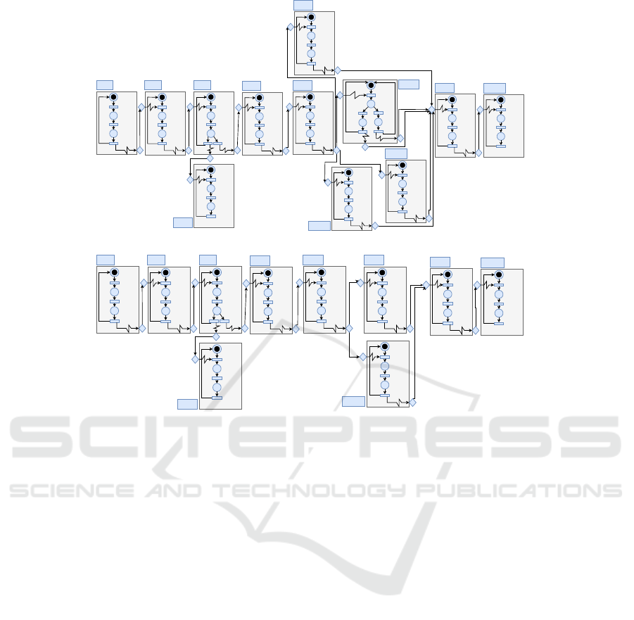
(a) Behavior module of RTN
Sys
01
.
P
1
P
2
P
3
t
1
t2
t3
[1,3]
P25
P26
P27
t26
t27
t28
[3,5]
P10
P11
P12
t11
t12
t13
[1,3]
P
4
P
5
P
6
t
4
t
5
t
6
[2,4]
P
7
P8
P9
t7
t8
t10
[2,4]
t9
P28
P29
P30
t29
t30
t31
[1,3]
CC
1
CC
2
CC
3
CC
5
CC
4
CC
6
CC
7
CC8
CC
9
CC
10
P13
P14
P15
t
14
t15
t16
[5,7]
P16
P17
P18
t17
t18
t19
[4,6]
P19
P20
P21
t20
t21
t22
[4,6]
P36
P37
P
38
t37
t38
t39
[4,6]
(b) Behavior module of RTN
Sys
02
.
Figure 1: Behavior module of RT N
Sys
01
and RT N
Sys
02
.
2.2.1 FESTO MPS
FESTO MPS is a well-studied system for research
and educational purposes which is defined and de-
tailed in (Hafidi et al., 2018; Ramdani et al., 2018).
It is composed of three units. The distribution con-
tains a pneumatic feeder and a converter. It for-
wards cylindrical workpieces from the stack to the
testing unit. The testing unit contains the detector,
the elevator and the shift out cylinder. The detec-
tion unit performs checks on workpieces for height,
material type and color. Workpieces that success-
fully pass this check are forwarded to the process-
ing unit. The processing unit is composed of a ro-
tating disk, drilling machines, a checker and an evac-
uator. The drilling of the workpieces is performed
as the primary processing of this MPS. The result of
the drilling operation is then checked by the checking
machine and the workpieces is forwarded for further
processing to another mechanical unit. FESTO MPS
performs three production modes: (i) High mode:
when Driller
1
and Driller
2
are both activated and
ready to work simultaneously, (ii) Medium mode:
when Driller
1
and Driller
2
are both activated but
work sequentially, (iii) Light mode: when only one
driller is activated at once. We denote Light
i
, when
Driller
i
/ i ∈ {1, 2} works. FESTO MPS is modeled
with an R-TNCES RT
FEST O
{B
FEST O
,R
FEST O
} such
that: B
FEST O
={High, Medium, Light
1
,Light
2
} is the
behavior module where the combination of CC
s
de-
scribes the system modes. As shown in Figure 1a.
R
FEST O
={r
H,L
1
,r
H,L
2
,r
H,M
,r
M,H
,r
M,L
2
,r
L
1
,L
2
} is a
set of different system reconfigurations. The set
of control chains describing FESTO MPS con-
trol system is presented as follows: Cchain
1
=
CC
1
,CC
2
,CC
3
,CC
4
,
Cchain
2
= CC
1
,CC
2
,CC
3
,CC
5
,CC
6
,CC
7
,CC
9
,CC
10
,
Cchain
3
= CC
1
,CC
2
,CC
3
,CC
5
,CC
6
,CC
8
,CC
9
,CC
10
,
Cchain
4
= CC
1
,CC
2
,CC
3
,CC
5
,CC
6
,CC
11
,CC
9
,CC
10
,
Cchain
5
= CC
1
,CC
2
,CC
3
,CC
5
,CC
6
,CC
12
,CC
9
,CC
10
.
This paper uses the description and the R-TNCES
model of FESTO MPS for the construction of the pro-
posed ontology as shown in Figure 4a.
2.2.2 THREADING HOLE SYSTEM
It is modeled using R-TNCES formalism. It is
composed of three units: (i) the distribution unit,
(ii) the testing unit, and (iii) the processing unit.
The first two units are used in FESTO MPS. The
processing unit is composed of a rotating disk,
threading hole machine, a checker and an evacuator
ICSOFT 2020 - 15th International Conference on Software Technologies
342
perform the threading of the workpiece holes as the
primary processing task of the system. The result
of the threading operation is then checked by the
checking machine and the workpieces are forwarded
for finally further processing to another mechanical
unit. Behavior module B
T HS
and ontology O
T HS
are
presented in Figure 1b and Figure 4b respectively on
page 6. such that:
B
T HS
={High, Light} is the behavior module shown
in Figure 1b. R
T HS
={r
H,L
,r
H,L
} is a set of different
system reconfiguration.
The set of control chains describing THS control
system is presented as follows:
Cchain
1
= CC
1
,CC
2
,CC
3
,CC
4
,
Cchain
2
= CC
1
,CC
2
,CC
3
,CC
5
,CC
6
,CC
7
,CC
8
,CC
9
,
Cchain
3
= CC
1
,CC
2
,CC
3
,CC
5
,CC
6
,CC
10
,CC
8
,CC
9
.
RDECS
Domain
Mode
Physical-
Process
UnitOWL:Thing
Is_Composed_Of
Has_Mode
Has_PhysicalProcess
Imply
Has SubClass
Has_Domain
Figure 2: Genric ontology.
2.3 Ontology Concept
As defined in (Ougouti et al., 2018) an ontology is
an explicit description of concepts or classes in a cer-
tain domain that constitutes a knowledge base. An
ontology is defined mathematically as quadruple O =
(C,S,Re,I) where: 1. C = c
1
,..,c
m
is a set of con-
cepts that refer to a real world objects. 2. S = s
1
,..,s
n
is a set of properties that refer to a property of a con-
cept, which is a value of a simple type such as Integer,
String or Date. 3. Re = Re
1
,..,Re
p
is a set of relation-
ships defined between concepts. 4. I = i
1
,..,i
q
, where
each i
w
is an instance of some concept c
x
∈C. It in-
clude a value for every property s
y
associated to c
x
or
its ancestors. An ontology can be presented graph-
ically as a formed graph O = G(C,E) where C is a
set of concepts linked by a set of directed edges E
which specifies concept relations. The function y de-
fines the type of edges, i.e., y : E → T where T is
the set of possible edge types (transitivity, symme-
try and reflexivity). We define an generic ontology
Gen = (C,S, Re,I), which is instantiated to model the
verified RDECS. Table 2 shows the defined concepts
∈C and their properties include in S. Figure 2 shows
the relations ∈ Re.
3 NEW STATE SPACE
GENERATION METHOD
We present in this section the proposed method for
state space generation during formal verification of R-
TNCESs. Using our proposed approach, we minimize
temporal complexity by proposing a distributed archi-
tecture on cloud server (Hayes, 2008). Thus, we im-
prove model-checking of reconfigurable systems and
make it more efficient.
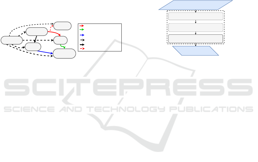
3.1 Motivation
System Model + Ontology Model
Ontology Alignement
Fragmentation + Elemetary
Accessbilty graph generation.
Accesibilty graph composition.
Accessibility graph.
Text
Accessibility graph
generation.
Figure 3: Global idea for State Space Generation.
The correctness of RDECSs can be ensured by a for-
mal verification. The exploration of the state space
is widely used for analyzing models formalized with
R-TNCES, or related formalisms. The complexity of
R-TNCES makes the verification task complex, be-
cause of combinatorial growth of the state space ac-
cording to the model size. The verification of an R-
TNCES requires the checking of each configuration,
namely each TNCES. TNCESs that describe the con-
figurations often present similarities which implies re-
dundant calculation during checking of these systems.
Thus we propose an adequate approach that avoids
many repetitive computations. To ensure this objec-
tive, this paper proposes a new method where verifi-
cation is executed in a distributed architecture to con-
trol R-TNCESs complexity. The formal verification
is performed through the following tasks: fragmenta-
tion, ontology alignment and accessibility graph com-
position. Figure 3 presents the main steps of the pro-
posed method.
3.2 Formalization
In this section, we present accessibility graph genera-
tion steps according to our proposed method.
3.2.1 Ontology Alignment
According to the definition presented in (Ougouti
et al., 2017), aligning two ontologies is to find a set of
On the Improvement of R-TNCESs Verification using Distributed Cloud-based Architecture
343
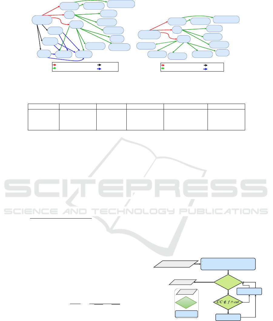
FESTO MPS
Medium
Low
Rotating-Disk
Process
Distribution
Test
Converter
Evacuator
Pneumatic feeder
Detector
Evactuator2
Tester
Driller1 Driller2
Checker
Is_Composed_Of
Has_Mode
Has_PhysicalProcess
Imply
High
(a) Ontology Osys
01
THREADING
HOLE SYSTEM
Rotating-Disk
Process
Distribution
Test
Converter
Evacuator
Pneumatic feeder
Detector
Evactuator2
Tester
Checker
Is_Composed_Of
Has_Mode
Has_PhysicalProcess
Imply
Threader2
Threader1
(b) Ontology Osys
02
Figure 4: Ontologies that describe Sys
01
and Sys
02
.
Table 2: Generic ontology which modeled RDECSs.
Concepts ∈C RDECS Domain Unit Physical Process Mode
Properties ∈ S
Id: String
Name: String
Description: Text
Id: String
Name: String
Id: String
Name: String
Description: Text
Id: String
Name: String
Description: Text
Control chain: String
Id: String
Name: String
Description: Text
correspondences, where each correspondence is de-
scribed by: a unique identifier Id, the concept c
i
∈O
1
,
the concept c
j
∈ O
2
and σ
i j
the degree of similar-
ity between c
i
and c
j
evaluated in the interval [0,1].
Formally, it is to find |O
1
|× |O
2
| correspondences
(Id
i j
,c
i
,c
j
,σ
i j
). A threshold τ is defined and com-
pared with σ
i j
. The correspondence is established
only if σ
i j
> τ. Global similarity σ
i j
is computed
through the following steps:
1. Compute semantic similarity by comparing con-
cepts neighbors using Tversky measurement:
T m
i j
=
|(n
i
∩n
j
)|
|(n
i
∩n
j
)|+α|(n
i
−n
j
)+β|(n
j
−n
i
)|
, where:
n
i
(resp. n
j
): Neighbor set of c
i
(resp. c
j
).
n
i
∩n
j
: Number of common neighbors between c
i
and c
j
.
n
i
−n
j
(resp. n
j
−n
i
): Number of neighbors that
exist ∈ n
i
and /∈ n
j
(resp. ∈n
j
and /∈ n
i
).
2. Compute lexical similarity, a weighted sum of
normalized Leveinstein and n-gram similarities:
SimLex
i j
= α ∗LevNorm(i, j) + β ∗g
(
i, j).
3. Compute partial similarity of concept descriptions
using the cosinus function:
SimDes
(A,B)
= cos(θ) =
A.B
|A||B|
=
∑
A×B
√
∑
A
2
×
√
∑
B
2
.
4. Compute linguistic similarity by combining Sim-
Lex and SimDes: SimLing
(i, j)
= αSimLex
(i, j)
+
βSimDes
(i, j)
. with α = 0.4 and β = 0.6.
5. Calculate the global similarity which is a
weighted sum of linguistic and semantic similar-
ity: σ
i j
= αSimLing
i j
+ βT m
i j
, with α = β = 0.5.
Running Example 1. Let O
FEST O
and O
T HD
two
ontologies, which describe the production systems
presented in subsection 2.2. Given two concepts
Process ∈ O
FEST O
and Process ∈ O
T HS
. Table 3
shows an application of ontology alignment where,
we compute: i) lexical similarity, which concerns
the concepts property ”Name”, ii) semantic similar-
ity, which concerns concepts neighbors, iii) descrip-
tion similarity, which concerns the concepts prop-
erty ”Description”, iv) linguistic similarity, which is
the combination of lexical and description similari-
ties, and v) global similarity by combining the said
similarities. σ(Process,Process) = 0.61 (low value)
and the threshold τ = 0.8 (fixed). We conclude that
Process ∈ O
Sys
FEST O
and Process ∈ O
Sys
T HS
are non-
similar. Thus, the non-similar and similar parts are ef-
ficiently distinguished and redundant calculations are
avoided.
3.2.2 Fragmentation
Fragment The RTN into a set of CCs.
Add the CCs into the waiting list Waiting.
Fragmentation(RTN,cor)
Waiting
= Null
Generate EAG
Set of EAGs
YES
NO
NO
YES
Input/Output
Decision
Process
Delete CC from
waiting
Figure 5: Operative steps of the fragmentation function
where Waiting is the list of CCs to be computed.
Fragmentation consists on decomposing an R-
TNCES into a set of CC and generating elementary
accessibility graph EAGs for CCs that are not con-
cerned by the correspondences computed in the pre-
vious step.
ICSOFT 2020 - 15th International Conference on Software Technologies
344
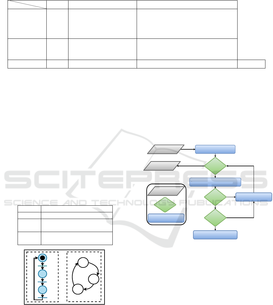
Table 3: Application of ontology alignment on running example where Concept
1
∈ O
FEST O
and Concept
2
∈ O
T HS
.
Concepts
Properties
Name Neighbors Descriptions
Concept 1 Process
{Driller1, Driller2,
checker, Evacuator
Rotating disk}
Workpieces that pass the test unit successfully are
forwarded to the rotating disk of the processing unit, where
the drilling of workpieces is done. It is assumed that in this
work there exist two drilling machines Drill1 and Drill2
to drill workpieces. The result of the drilling operation is
next checked by a checker and finally the finished product is
removed from the system by an evacuator.
Concept 2 Process
{Threader1, Threader2, checker, Evacuator
Rotating disk}
Workpieces are received by rotating disk of the process unit,
where the threading of workpieces is done. It is assumed that
in this work there exist one threading hole machine to thread
workpieces. The result of the is next checked by a and finally
the finished product is removed from the system by an evacuator.
Similarities SimLex = 1 T m = 0.46 Simdes = 0.6
SimLing = 0.76
σ = 0.61
Running Example 2. To show the application of
fragmentation, we consider production systems pre-
sented in Subsection 2.2. They are modeled by
RT
FEST O
(to be verified) and RT
T HS
(already veri-
fied). Let cor be a set of correspondences com-
puted during alignment of O
FEST O
and O
T HS
. Ta-
ble 4 and Figure 6 show application of fragmentation
on RT
FEST O
. It runs in two steps: 1. decomposing
RT
FEST O
into a set of CC f = {CC
1
,..,CC
12
}, and
2. computing elementary accessibility graphs EAGs
of each CC /∈ f ∩cor. During fragmentation, CCs
synchronization transitions are stored for reuse when
composing the accessibility graph AG. Real RDECSs
encompass millions of transitions, which increases
accessibility graph generation complexity. Fragmen-
tation allows us to control complexity. Moreover, it
allows us to deal with internal similarities.
Table 4: Application of fragmentation on FESTO MPS.
System FESTO MPS
f {CC
1
,..,CC
12
}
cor
{CC
1
,CC
2
,CC
3
,
CC
4
,CC
5
,CC
6
,CC
10
}
EAGs
EAG
CC
7
,EAG
CC
8
,EAG
CC
9
,
EAG
CC
10
, EAG
CC
11
,EAG
CC
12
p
2
p
1
p
2
p
3
t
1
t
2
t
3
p1
p
3
t
1
t
2
t
3
CC
1
EAG
cc1
Figure 6: CC
1
with its elementary accessibility graph.
3.2.3 Planning
We set up a priority order for accessibility graph com-
position. Let RT N be a system modeled by R-TNCES
and described by ontology O
sys
. We extract from O
sys
control chains Cchains. Cchains are then en-queued
to a queue Q depending on their length such as the
smallest one is en-queued firstly.
Running Example 3. By using the behavior module
B of RT N
FEST O
, the composition plan to be followed
for AG
FEST O
generation for test failure case described
by C
chain
1
is presented as follows:
EAG
CC
1
× EAG
CC
2
> PAG
CC
12
×CC
3
> PAG
123
×
CC
4
.
3.2.4 Accessibility Graph Composition
Create the Initial node.
Add the node to Waiting.
Search for the set of passable
transitions t.
Waiting
= Null
Find t ?
t = NULL
Create the successor node.
Add the node to Waiting.
Delete the currentnode
from Waiting.
The Composed
Graph
Composition
(AG , AG')
NO
NO
NO
YES
YES
YES
Input/Output
Process
Decision
Figure 7: Operative steps of the graph composition func-
tion, where t is the set of the fixed passable transition and
Waiting is the list of nodes to be computed.
Full accessibility graph AG is computed by com-
posing EAGs computed during fragmentation step
and partial accessibility graphs PAGs retrieved during
ontology alignment step as shown in Figure 7. The
composition is done according to the established plan.
Running Example 4. During AG
FEST O
generation,
several composition of EAGs are executed. Indeed,
we run Composition(EAG
CC
1
,EAG
CC
2
) function to
obtain PAG
12
shown in Figure 8. It proceeds as fol-
lows:
1. Creates initial state S
0
by concatenating ini-
tial states S
0
0
and S
00
0
of both EAG
CC
1
and EAG
CC
2
,
2. searches the set of enabled transitions from S
0
0
and
S
00
0
, and 3. checks whether the transition t is a com-
mon transition. If yes, then we create a new state S
1
On the Improvement of R-TNCESs Verification using Distributed Cloud-based Architecture
345

S'
0
EAGcc2
S
0
EAGcc1
S
3
S
1
S
2
S
4
S
5
S
6
S
8
S
7
PAG
12
S''
0
S'
2
S'
1
S''
2
S''
1
Composition(EAGcc1,EAGcc2)
Figure 8: Compostion of EAGcc1 & EAGcc2.
by concatenating the current target states from S
0
0
and
S
00
0
. Otherwise, if t belongs only to EAG
CC
1
, then a
new state S
1
is obtained by concatenating the current
state S
00
0
from EAG
CC
2
and the current target state S
0
1
from EAG
CC
1
and vice versa.
We repeat these steps for the remaining states until
we get the whole state space.
4 DISTRIBUTED CLOUD-BASED
STATE SPACE GENERATION
This section presents Cloud-based distributed archi-
tecture and how to perform formal verification on it.
4.1 Distributed Architecture for State
Space Generation
In this subsection, we present the proposed hierarchi-
cal and distributed architectures shown in Figure 9.
The idea that motivates the development of this archi-
tecture is to increase computation power and storage
availability. It is composed of computational and stor-
age resources. To develop the architecture shown in
Figure 9 we need the following units.
• Computational Units: Execute tasks defined in
subsection 3.2 by means of M+n machines where:
Sub-Workers
Load Balancer
TheMaster
Database
INTERNET
GATEWAY
Text
Text
W1
W2 W3 W4
USER
Figure 9: Distributed architecture for formal verification.
(i) M represents the number of machines (i.e.,
5 machines in our approach). The set of ma-
chines are composed of a master and four work-
ers W
1
,...,W
4
that have specific tasks. (ii) n is the
number of sub-workers that execute the high com-
plex tasks (i.e., EAGs generation and PAGs com-
position). n depends on system size.
• Storage Unit: represents the allocated cloud
database that stores domain ontologies, EAGs
temporary and PAGs permanently.
4.2 Distributed State Space Generation
This subsection presents the process of distributed
Formal verification on a cloud based architecture.
Running Example 5. The user sends a verification
request req(R
FEST O
: R-T NCES,O
FEST O
: Ontology).
The master ensures tasks coordination by receiv-
ing the verification request and sending R
FEST O
and
O
FEST O
to workers to carry out their tasks as follows.
1. sending simultaneously ontology O
FEST O
to
workers W
1
, W
4
and R
FEST O
to worker W
2
,
2. waiting signals from W
1
and W
2
and to receive the
composition plan from W
4
to forward it to W
3
.
3. waiting signal from W
3
to allow beginning ontol-
ogy fusion by W
1
.
W
1
has two main tasks: (i) Ontology alignment to
extract correspondences and (ii) Ontology fusion to
update domain ontology-based history, we merge
O
FEST O
AND O
D
.
W
2
: At the reception of R
FEST O
, it proceeds to
the fragmentation, sends CCs to sub-workers after
applying a load balancer algorithm and sends a signal
to master which announces the end of these two
tasks: fragmentation and generation of EAGs.
W
3
receives the composition plan and collects the
elements that it needs from the database for the AG
composition. Finally, it sends a signal to master
which announces the end of its task.
W
4
is responsible for planning compositional order
for full accessibility graph generation. It extracts the
control chains concepts from O
FEST O
. Then the plan
is sent to the master.
4.3 Implementation
In this subsection, we present the main algorithms
used in our approach.
Algorithm 1 describes the fragmentation task. It
decomposes the R-TNCES in a set of CCs and gener-
ates their accessibility graphs EAGs.
ICSOFT 2020 - 15th International Conference on Software Technologies
346

Algorithm 2 describes the steps for the full acces-
sibility graph composition AG. It composes the ac-
cessibility graphs recovered thanks to the ontology
alignment and the ones computed during fragmenta-
tion to return the full accessibility graph of the veri-
fied model.
Algorithm 1: Fragmentation.
Input: RT N: R-TNCES; T N
0
: TNCES;
Output: S EAG: Set of elementary accessibility
graphs;
for int i = 0 to |
∑
T N | do
for each CC ∈ T N do
if ( !Tagged (CC)) then
Insert(S EAG,Geneate State Space(CC));
tag(CC);
end
end
end
return S EAG
Algorithm 2: State Space Composition.
Input: S AG: Set of accessibility graphs(EAG,
PAG) ;
∑
CChain: Set of Cchains ;
Output: AG: Set Accessibility graphs;
for int i = 0 to |
∑
CChain | do
AG ← EAG
CC
0
i
;
for int j = 0 to |
∑
CC
i
| do
AG ←Compose(AG,EAG
CC
j
i
);
end
end
return AG
4.4 Complexity of Distributed State
Space Generation
The verification is based on three main functions: (i)
the ontology alignment, (ii) the fragmentation, and
(iii) the EAG/PAGs composition. The ontology align-
ment complexity on this scale is always polynomial,
thus we focus on the two other function presented re-
spectively in Algorithm 1 and 2. As mentioned in
(Zhang et al., 2013), TNCES verification complex-
ity is expressed by O(e
t
) where t is the number of
transition, in our case, we use it for each CC of the
verified R-TNCES. For an R-TNCES with TN = |B|
the number of TNCESs composing the verified R-
TNCES and C the average number of CCs that every
TNCES contains, The complexity of Algorithm 1 is
O(T N ×C ×e
t
). For a composed graph with n
0
the
number of nodes computed by the composition graph
function and j the average number of the enabled
transitions from each state, Algorithm 2 complexity
is expressed by (n
0
× j). Thus, verification time com-
plexity is: O((T N ×C ×e
t
) + (n
0
× j)). Therefore,
our method complexity is expressed by
O(max O(T N ×C ×e
t
),O(n
0
× j)) = O(T N ×C ×e
t
).
The complexity of methods presented in (Zhang et al.,
2013; Hafidi et al., 2018) is O(e
m
×T N) with m ×
T N = T N ×C ×t. Thus, to assert that our complexity
is better, we have to prove that: O((T N ×C ×e
t
) <
O((T N ×e
m
), which is intuitively correct.
5 EVALUATION
The performance of the proposed verification method
is evaluated in this section. We make a compari-
son between the proposed method, that uses a dis-
tributed tool to compute accessibility graphs, and the
method reported in (Hafidi et al., 2018) that uses Rec-
AG tool. Then we proceed to different evaluations in
large scale systems by considering different similari-
ties. The external similarity rate of R-TNCES R
1
with
descriptive ontology O
L
is given by the following for-
mula.
ExternalSimilarity(R
1
) =
AlignedConcepts(O
L
)
Concepts(O
L
)
(2)
where, (i) AlignedConcepts(O
L
) returns the number
of similar concepts between O
L
and the related do-
main ontology O
D
, (ii) Concepts(O
L
) returns the to-
tal number of concepts that O
L
contains. The internal
similarity rate is given by the adapted method used in
(Hafidi et al., 2018) as follows.
InternalSimilarity(R
1
) =
Max({SimCC(T N
i
,T N
j
)}
i, j∈0...(n−1) and i< j
)
Max(NumberO f CC(T N
k
))
(3)
where, (i) SimCC(T N
i
,T N
j
) is the function that re-
turns the number of similar control components be-
tween two TNCESs, (ii) NumberO fCC() takes a
TNCES and returns its number of control compo-
nents, and (iii) Max() returns the maximum among
a set of natural numbers. We define three degrees of
Internal Similarity (resp, External Similarity): High,
Medium and low where, InternalSimilarity (resp,
ExternalSimilarity) is 50%-100%, 20%-50% and 0%-
20%.
5.1 Evaluation in Large Scale Systems
Considering External Similarity
Figure 10 describes the verification result of an R-
TNCES model by considering three levels of external
On the Improvement of R-TNCESs Verification using Distributed Cloud-based Architecture
347
0 100 200 300 400
0
500
1,000
Nodes
Computed states
Low Similarity
0 100 200 300 400
Nodes
Medium Similarity
0 100 200 300 400
Nodes
High Similarity
Cammili tool (Camilli et al., 2014) Rec-AG tool (Hafidi et al., 2018) Proposed tool
Figure 10: Proposed verification in large scale systems considering external similarity.
similarity. The model is composed of three TNCESs
represented by three parallel control chains of equal
length, with Complexity(CC
i j
) = 3, i ∈ 1...100 and
j ∈ 1...3 (i.e., each CC contains 3 nodes). By analyz-
ing the plots in Figure 10, we notice that:
In the case of low external similarities, the number
of states computed using the proposed method and
the one proposed in (Hafidi et al., 2018) in its best
case (i.e., in the case of a high internal similarity rate)
becomes nearly equal with the ascent of the number
of system nodes. It is explained by the fact that the
difference in the number of nodes to explore is min-
imal and becomes non-significant when the system
is larger. Nevertheless, low similarity must be ex-
ploited because it improves the results in both cases
of medium and high internal similarity.
In the case of high and medium external similari-
ties: the proposed method takes advantage of those
presented in (Camilli et al., 2014) and (Hafidi et al.,
2018). It is explained by the fact that the number
of nodes to explore is reduced. Thanks to the exter-
nal similarity that allows us to eliminate redundan-
cies. While in the three cases, the proposed method
presents better results than the one used in (Camilli
et al., 2014), which generates AGs via the classical
methods. The proposed method can reduce calcula-
tions by more than 50%, depending on model size and
similarity rates. This represents the main gain of the
paper.
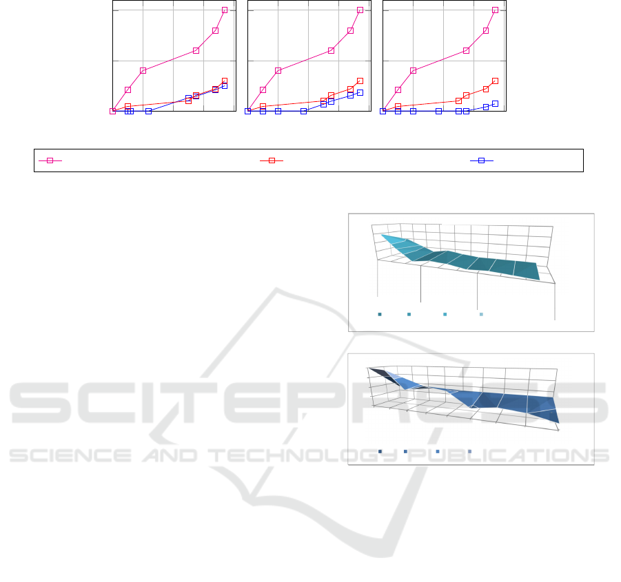
5.2 Evaluation in Large Scale Systems
by Considering External and
Internal Similarities
The surfaces in Figure 11 describe the results of both
the proposed method and the one used in (Hafidi
et al., 2018), by using three factors: External simi-
larities, internal similarity and nodes to be explored
for a state generation. In their worst case (i.e.,
States
Nodes
0
100
200
300
400
low
Medium
high
(1) Rec-AG-vérification
0-100 100-200 200-300 300-400
States
Nodes
0
100
200
300
400
low
Medium
High
low
Medium
High
low
Medium
High
Low
Medium
High
(2)Proposed-Verification
0-100 100-200 200-300 300-400
(1) Rec-AG-Verification
(1) Proposed Verification
(2)
(a)
States
Nodes
0
100
200
300
400
low
Medium
high
(1) Rec-AG-vérification
0-100 100-200 200-300 300-400
States
Nodes
0
100
200
300
400
low
Medium
High
low
Medium
High
low
Medium
High
Low
Medium
High
(2)Proposed-Verification
0-100 100-200 200-300 300-400
(1) Rec-AG-Verification
(1) Proposed Verification
(2)
(b)
Figure 11: Proposed verification in large scale systems con-
sidering external and internal similarities.
InternalSimilarity = ExternalSimilarity = 0%) per-
formance of both methodologies presents limits, with
same results using the method reported in (Zhang
et al., 2013). However, in the remaining cases, the
proposed method always presents better results ac-
cording to similarity rates. It performs best with:
(i) Less computed states, thanks to the external source
of partial graphs and elimination of internal redundan-
cies, and (ii) less nodes to be explored for state space
generation thus less complexity to generate a state,
thanks to the incremental way used when composing
the accessibility graph.
6 CONCLUSION
This paper deals with formal verification of RDECSs
that we model with R-TNCES. The proposed method
aims to improve the state space generation step by
ICSOFT 2020 - 15th International Conference on Software Technologies
348

using a distributed architecture. We developed a
distributed architecture with three hierarchical lev-
els (Master, worker and sub-worker) and a cloud-
based-storage (Amazon Simple Storage S3 (Murty,
2008)). It allows us to increase computational power,
data availability and to perform parallel execution.
The proposed improvement incorporates ontologies
for RDECSs verification. We set up an ontology-
based history, which allows us to detect external sim-
ilarities thanks to an ontology alignment. Thus, we
avoid many redundant calculation. In order to deal
with internal similarities, we introduce modularity
concept by affecting specific tasks to each unit of our
architecture, including fragmentation and accessibil-
ity graph composition, which allow us to deal with
RDECSs fragment by fragment and to construct in-
crementally accessibility graphs. An evaluation is re-
alized and experimental results are reported. The re-
sults prove the relevance of the developed architec-
ture and the improvement of state space generation.
Nevertheless, by comparing our work with other veri-
fication methods, we identified cases, that provide re-
sults which tend toward the works reported in (Zhang
et al., 2013) and (Hafidi et al., 2018). Indeed, our
method provides less benefits in case of low internal
or external similarities. However, despite the minor
gain when internal similarity is low, it is important to
consider this case the ontology-based history enrich-
ment. Future works will: 1. Deploying the distributed
architecture in Amazon Elastic Compute Cloud (EC2)
(Murty, 2008). 2. Optimizing the state space analyz-
ing step for RDECSs formal verification. 3. Extend-
ing the proposed tool to support other formalism that
models RDECSs.
REFERENCES
Ben Salem, M. O., Mosbahi, O., Khalgui, M., Jlalia, Z.,
Frey, G., and Smida, M. (2017). Brometh: Methodol-
ogy to design safe reconfigurable medical robotic sys-
tems. The International Journal of Medical Robotics
and Computer Assisted Surgery, 13(3):e1786.
Camilli, M., Bellettini, C., Capra, L., and Monga, M.
(2014). Ctl model checking in the cloud using mapre-
duce. In Symbolic and Numeric Algorithms for Sci-
entific Computing (SYNASC), 2014 16th International
Symposium on, pages 333–340. IEEE.
Gadelha, M. Y., Ismail, H. I., and Cordeiro, L. C. (2017).
Handling loops in bounded model checking of c pro-
grams via k-induction. International Journal on Soft-
ware Tools for Technology Transfer, 19(1):97–114.
Hafidi, Y., Kahloul, L., Khalgui, M., Li, Z., Alnowibet, K.,
and Qu, T. (2018). On methodology for the verifica-
tion of reconfigurable timed net condition/event sys-
tems. IEEE Transactions on Systems, Man, and Cy-
bernetics: Systems, (99):1–15.
Hayes, B. (2008). Cloud computing. Communications of
the ACM, 51(7):9–11.
Khalgui, M., Mosbahi, O., Li, Z., and Hanisch, H.-M.
(2011). Reconfiguration of distributed embedded-
control systems. IEEE/ASME Transactions on Mecha-
tronics, 16(4):684–694.
Koszewnik, A., Nartowicz, T., and Pawłuszewicz, E.
(2016). Fractional order controller to control pump in
festo mps
R
pa compact workstation. In 2016 17th In-
ternational Carpathian Control Conference (ICCC),
pages 364–367. IEEE.
Murty, J. (2008). Programming amazon web services: S3,
EC2, SQS, FPS, and SimpleDB. ” O’Reilly Media,
Inc.”.
Ougouti, N. S., Belbachir, H., and Amghar, Y. (2017). Se-
mantic mediation in medpeer: An ontology-based het-
erogeneous data sources integration system. Interna-
tional Journal of Information Technology and Web En-
gineering (IJITWE), 12(1):1–18.
Ougouti, N. S., Belbachir, H., and Amghar, Y. (2018).
Proposition of a new ontology-based p2p system for
semantic integration of heterogeneous data sources. In
Handbook of Research on Contemporary Perspectives
on Web-Based Systems, pages 240–270. IGI Global.
Padberg, J. and Kahloul, L. (2018). Overview of reconfig-
urable petri nets. In Graph Transformation, Specifica-
tions, and Nets, pages 201–222. Springer.
Ramdani, M., Kahloul, L., and Khalgui, M. (2018). Au-
tomatic properties classification approach for guiding
the verification of complex reconfigurable systems. In
ICSOFT, pages 625–632.
Souri, A., Rahmani, A. M., Navimipour, N. J., and Rezaei,
R. (2019). A symbolic model checking approach in
formal verification of distributed systems. Human-
centric Computing and Information Sciences, 9(1):4.
Valmari, A. (1996). The state explosion problem. In
Advanced Course on Petri Nets, pages 429–528.
Springer.
Zhang, J., Khalgui, M., Li, Z., Mosbahi, O., and Al-Ahmari,
A. M. (2013). R-tnces: a novel formalism for recon-
figurable discrete event control systems. IEEE Trans-
actions on Systems, Man, and Cybernetics: Systems,
43(4):757–772.
On the Improvement of R-TNCESs Verification using Distributed Cloud-based Architecture
349
