
A Multi-domain Network Simulator based on NS-3
Van Thanh Le, Nabil El Ioini, Hamid R. Barzegar and Claus Pahl
Department of Computer Science, Free University of Bozen/Bolzano, Italy
Keywords:
LTE, Roaming, Simulation, Multi-domain, NS-3, Connected Car.
Abstract:
With telecommunication technology development now moving to a different generation of wireless commu-
nication from 4G to 5G, user connections become faster and more reliable. However, from the view of appli-
cation developers, there is still a testbed environment lacking to evaluate their systems reliability and perfor-
mance. In this paper, we present an extension for the LTE module collaboration via roaming based on NS-3
simulator, which will provide an ecosystem for on-car service testing as a sample context. We also evaluate
the model with specific metrics to check whether the model is adaptable to real-time processes.
1 INTRODUCTION
Distributed systems and computer networks are at the
core of cloud computing, which contains both com-
plex hardware and software infrastructures (Princy
and Nigel, 2015). However, the high cost of building
and testing real infrastructures calls for alternative so-
lutions to give clear indications about the reliability
and performance of the system before even building
it. For decades simulations have been used to evaluate
different aspects of software systems and test differ-
ent configuration settings. In this paper, we describe
our effort in designing and building a simulation en-
vironment module to support roaming services.
Followed by (Huawei, 2020), the roaming ser-
vices facilitates service accessing by mobile users
from outside of home network, roaming is only al-
lowed with the visited network having similar net-
work standards and signed roaming agreement with
the home network.
In particular, we focus on building a cross-domain
Long Term Evolution - Evolved Packet Core (LTE-
EPC) model, which will be applied for on-car services
when changing its service providers, in other words,
the car crosses its country borders or gets far from its
current connected Base Station (BS).
Traditionally, on-car services as multimedia
or gaming will connect with the nearest Base
Transceiver Station (BTS in 3G or eNodeB in 4G),
the data flow will be established from a server to the
running service via the core network and telecommu-
nication infrastructure. A problem happens when the
car moves far from the current BTS, the network sig-
nal will become weaker and then unstable, the current
mobile network solves this problem by disconnecting
with the connected BTS and then reconnect with the
next nearest one. All mobile sessions from the pre-
vious BTS also move to the next, and services also
need to reconnect, this behavior is called handover or
handoff (HO). The handover event will be triggered
when the serving cell becomes worse than a specific
threshold, the value could be measured by Reference
Signal Receive Power (RSRP) or Reference Signal
Received Quality (RSRQ).
There are two cases for services after the handover
event, the first case is to connect with the same LTE
network, in other words, this is the Intra-operator han-
dover, and other kind of handover between two inde-
pendent LTE, which is called Inter-operator handover.
These concepts will be explained in the background
section. The first case is already implemented in the
LTE-EPC module in NS-3, thus we focus on the other
case and evaluate it in this paper.
The handover between two LTE raises some issues
for our simulator:
• When should we trigger the handover event? Sim-
ilar to intra-operator handover, we have to define
a threshold-based RSRQ or RSRP to trigger the
event.
• Which is a suitable route for User Equipment
(UE) requests? After the handover, requests from
UE could follow the roaming route to come back
to the home network to access the original server
or request a new server from the visited network.
• Which UE’s information should be kept after han-
Le, V., El Ioini, N., Barzegar, H. and Pahl, C.
A Multi-domain Network Simulator based on NS-3.
DOI: 10.5220/0009831602170224
In Proceedings of the 10th International Conference on Simulation and Modeling Methodologies, Technologies and Applications (SIMULTECH 2020), pages 217-224
ISBN: 978-989-758-444-2
Copyright
c
2020 by SCITEPRESS – Science and Technology Publications, Lda. All rights reserved
217

dover? Keeping connections with an LTE network
requires session information as IP address, Inter-
national Mobile Subscriber Identity (IMSI), UE
session in BTS, etc. We have to decide which data
should be updated for the new LTE and which one
should be maintained.
The rest of the paper is organized as follows: we
will start with the background to show concepts in
LTE, the next is the core technologies we used to build
our architecture. Section four is about related work,
the architecture design and evaluation are in section
five and six respectively and the last one is conclusion.
2 BACKGROUND
This section will present general concepts related to
network communication and components. These fun-
damental studies will be used for our further coming
implementation.
2.1 LTE Main Components
We introduce LTE components here to get a bet-
ter understanding of our further design. 4G/LTE ar-
chitecture divides into two main sets which are the
Evolved Universal Terrestrial Radio Access Network
(E-UTRAN) from LTE and the EPC (Page and Dricot,
2016).
E-UTRAN is the radio access network and con-
tains eNodeB which will handle requests from UE
(user equipment) and forwards them to EPC. EPC is
the core network of LTE architecture which consists
of the following components:
• MME: stands for Mobility Management Entity
that manages UE access network and mobility as
well as establishing the bearer path for UE.
• S-GW: means Serving GateWay, the main func-
tion of S-GW is to forward or route user data
packages. It also controls inter-eNodeB handover
and provides mobility between LTE and other
types of networks.
• P-GW: Packet GateWay provides connectivities
from UE to external networks by being the point
of exit and entry for UE requests.
• HSS: Home Subscriber Server that presents for a
central database that contains user information.
Each component in EPC is connected by inter-
faces which is shown in Figure 1.
Figure 1: LTE architecture.
2.2 Handover Techniques
In cellular networks, handover techniques perform an
essential role for the user seamless connection while
moving. An efficient handover scheme will enhance
the quality of service and provide flawless mobility.
(Tayyab et al., 2019) have classified handover types:
• Inter-/Intra-frequency handover: an intra-
frequency neighbour is referred to a target
eNodeB which operates on the same carrier
frequency, in another case, the eNodeB operates
different frequency which is called an inter-
frequency neighbour, respectively, we also have
inter-/intra-frequency handover.
• Inter-/Intra-cell layer handover: HetNets (Hetero-
geneous network, includes macro, micro, and pic-
ocell layers) provide a multiplicity of cellular lay-
ers to handle the capacity demand of users if han-
dover requests come from the same layer, it is
called Intra-cell layer handover, otherwise, it is
Inter-cell layer handover.
• Inter-/Intra-RAT handover: RAT stands for Radio
Access Technology, similar to other kinds of han-
dover, a handover event happens in the same RAT
will be Intra-RAT handover, with different RAT,
this is Inter-RAT handover.
• Inter-/Intra-operator handover: This can occur be-
tween systems controlled by an administrator or
an operator called Intra-operator handover, Inter-
operator one is another case. Roaming is an ex-
ample of Inter-operator handover.
(Tayyab et al., 2019) showed measurement con-
cepts with RSRQ and RSRP, and steps by steps for
Intra-handover. RSRP is the average received power
without interference and noise components, RSRQ is
calculated as the ratio of RSRP and RSSI (Received
Signal Strength Indicator) while RSSI is the total re-
ceived power including noise and interference. In this
paper, we focus mainly on Inter-operator handover
with MME change, or in other words, the case of
roaming that we will investigate hereafter.
SIMULTECH 2020 - 10th International Conference on Simulation and Modeling Methodologies, Technologies and Applications
218
2.3 Roaming Procedure
According to technical paper (Huawei, 2020) (GSM,
1997) and the handover process in (Tayyab et al.,
2019), the handover procedure in the roaming case
generally is described following steps:
1. The UE sends an initial request to access the LTE
home network (HPMN - Home Public Mobile
Network) for the first time, eNodeB forwards the
request to SGW and then MME, MME checks the
validity of UE via HSS before responding.
2. The UE is accepted to send another request for
services.
3. The UE measurement procedure is configured by
the serving eNodeB according to access restric-
tion and roaming information.
4. The UE sends an Measurement Report (MR) to
the serving eNodeB.
5. Based on the MR, the serving eNodeB could make
a handover decision for Intra-neighbor but the
next eNodeB is not in the same LTE network so
the current eNodeB keeps responding.
6. From UE, the next eNodeB signal is stronger than
a specific threshold with the current connected
eNodeB.
7. The UE detaches from the old cell in-home net-
work and requests to connect with the target cell
(new cell) in the visited network (VPMN - Visited
Public Mobile Network).
8. In the visited network, eNodeB receives an initial
request to connect, it is forwards to SGW and then
MME.
9. MME fails to verify the identity of HSS, it re-
quests to the HSS of the home network via S6a
interface.
10. HSS from the home network confirms the UE
identity, from now, UE can access the visited net-
work with two cases of service requests. Its IP
address will be updated followed by the network
while its IMSI is still maintained.
(a) Requested service is available in the visited net-
work: service data flow will be sent to PGW of
visited network and then its server as normal
(Visited server requests).
(b) Requested service is not available in the vis-
ited network: the service request follows S8 in-
terface to come back the home PGW and then
home core network (Roaming server requests).
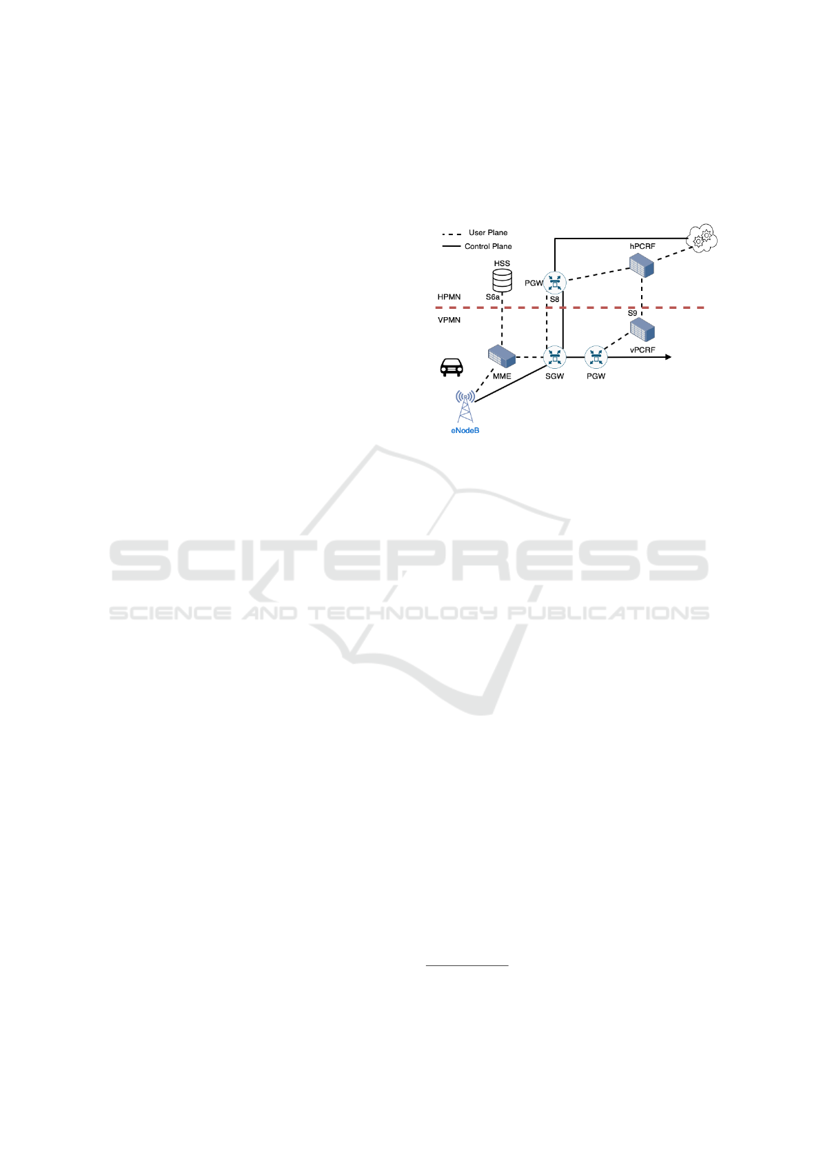
Figure 2 illustrated the roaming flow in LTE ar-
chitecture between two adjacent network. Besides
described components, we also have PCRF (Policy
and Charging Rules Function) for both visited and
home network (vPCRF and hPCRF), which take care
of managing quality of service, it communicates with
PGW via Gx interface.
Figure 2: LTE roaming architecture.
3 CORE TECHNOLOGIES
NS-3 (Riley and Henderson, 2010) is a discrete-event
network simulator that is free and open-source soft-
ware. The goal of NS-3 is to develop a simulation
environment suitable for networking research. NS-
3 is maintained by a worldwide volunteer team and
releases a new stable version for every three months
with a new model developed.
Besides network simulator supports, NS-3 also
provides real-time scheduler to facilitate a number of
simulation-in-the-loop use cases for interacting with
real systems. NS-3 can receive or send packages from
a real network or serve as an interconnection frame-
work between virtual machines. Here, we developed
our model based on the NS-3 simulator functions.
There are two main components of EPC-LTE in
NS-3 as LTE module and EPC module. The LTE
module (Piro et al., 2011) provides a basic implemen-
tation of LTE devices, including propagation models
and PHY and MAC layers. It focuses on modeling the
E-UTRAN part of a system that contains eNodeB and
UE with their channel connections as Radio Resource
Management, Packet Scheduling, and Dynamic Spec-
trum Access. The EPC module (Baldo et al., 2012)
includes core network interfaces, protocols, and en-
tities as PGW, SGW and MME. Interfaces connect-
ing components also presented there. The EPC-LTE
structure and component details are online
1
1
https://www.nsnam.org/docs/models/html/lte-design.
html
A Multi-domain Network Simulator based on NS-3
219
4 RELATED WORK
Besides concepts with paper referred to in Section 2,
we would investigate paperwork about roaming archi-
tecture based NS-3, but we found no simulators work-
ing that way.
Another point we would like to focus on is about
the NS-3 interaction with the real world application.
(Quinlan et al., 2016) propose a platform based NS-3
to simulate Dynamic Adaptive Streaming over HTTP
(DASH), their work also inherit the LTE module from
LENA project to build an LTE environment which is
set up in an independent computer. Tap bridge is in-
stalled to connect interfaces from the computer with
Raspberry Pi machines. They provide their configu-
ration with source code
2
, which is useful for our ex-
tension. (Sabbah et al., 2018) extend the LTE-EPC
module with CORE (Common Open Research Emu-
lator) to facilitate large-scale real-time network traf-
fic, they built a topology with several LTE-EPC, each
eNodeB in LTE will make a local controller for UEs.
They experiment with 32 EPCs, 2 eNodeBs per each
EPC and 5 UEs for each eNodeB. Their result is com-
prehensive with a large-scale model that can support
our work to scale up, however, to overcome the prob-
lem of the EPC communication, remote hosts of each
EPC connects to each others to form a ring topology,
so UEs always can connect to its original host.
Moreover, Docker container enables us to build
a flexible environment, we also want a combination
of Docker and NS-3, J.A.Alvarez Aldana explains
his work
3
with port connection and traffic flows be-
tween Docker and NS-3, configuration and environ-
ment setup are presented in detail. (Portabales and
Nores, 2018) also extend from the work of Aldana to
make the simulator adaptable with IoT simulations,
they even pack their NS-3 work into a Docker con-
tainer to make the flexible deployment. We could fol-
low their work to extend our model.
Our previous work (Le et al., 2019), (?) built a
Mobile Edge Cloud management based on blockchain
(?), (?), the LTE simulator inherits from SimuLTE
(Virdis et al., 2014) which runs on OMNetpp envi-
ronment (Varga and Hornig, 2008) and INET (Varga,
2020), and the mobility simulator is controlled by
Veins (Sommer et al., 2008) and Sumo (Behrisch
et al., 2011). However the work does not present
fully the concept of changing domain in the LTE net-
work, eNodeBs are still connected to share user ses-
sion while higher network layers as PGW or MME
does not collaborate to exchange the user data. So
2
https://www.ucc.ie/en/misl/research/software/
lanman2016/
3
https://chepeftw.github.io/NS3DockerEmulator
we decide to build an architecture based on NS-3
which attracts more attention and contributions from
the community, so the upgrade and improvement for
our architecture will be more easier.
5 ARCHITECTURE DESIGN
In this section, we propose an architecture for the
multi-domain LTE simulator, we will start with a gen-
eral design and then go in detail later.
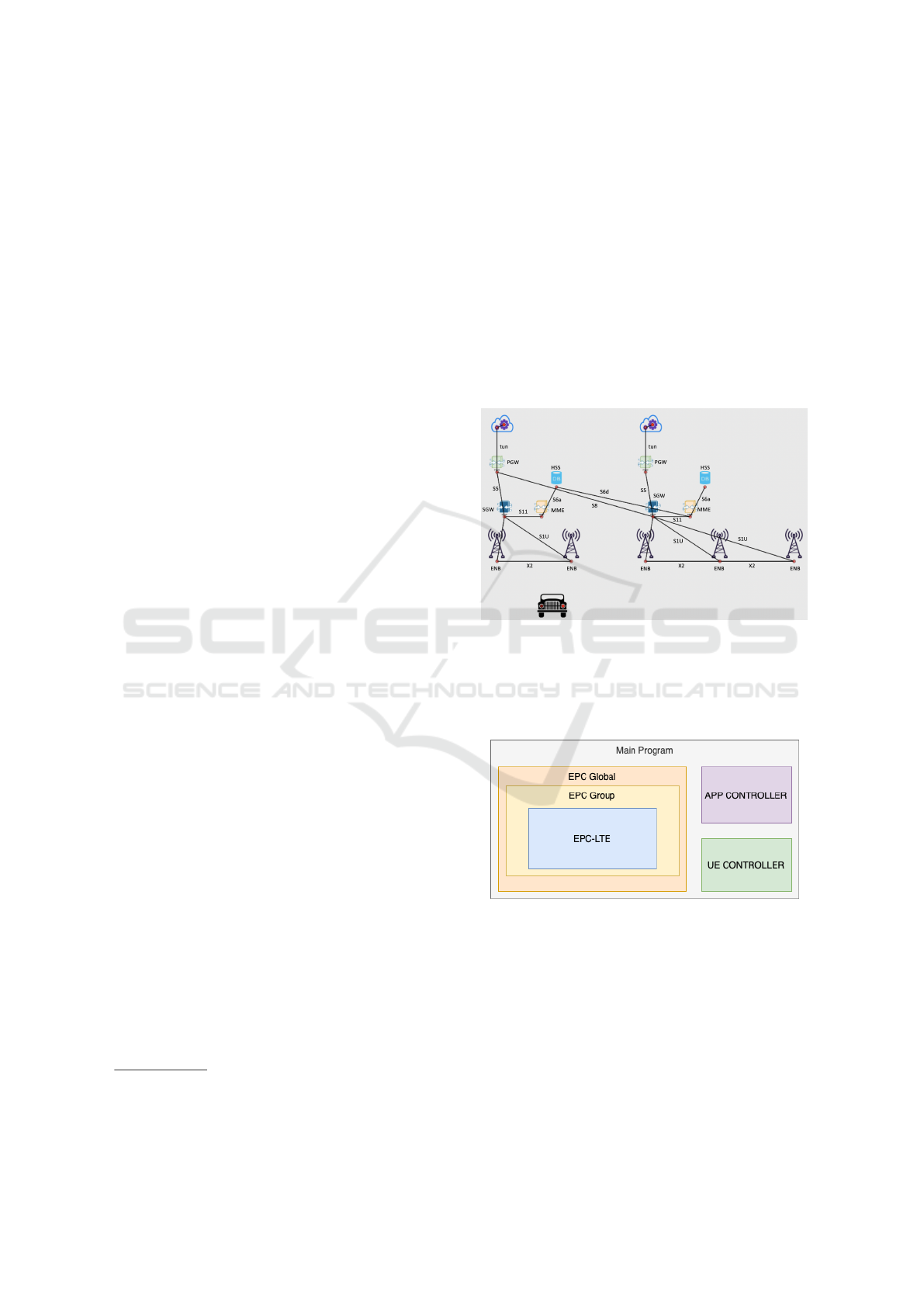
5.1 General Design
Figure 3: General design.
We prepare two independent LTE models and enable
them to interact with others via the roaming channel
and with UE (see Figure 3). The roaming channel is
built with two main interfaces as S6d and S8.
Figure 4: Additional modules.
The default LTE-EPC module of NS-3 as de-
scribed above only supports a single LTE channel,
components as PGW, SGW are set as fixed IP address,
so we try to extend the model by adding external com-
ponents as following:
• EPC Group: It separates PGW, EnB, SGW,
Server, with the main program, we suppose that a
region will keep an EPC group. Each EPC group
has its right to update the IP address of compo-
nents as long as the subnet mask.
SIMULTECH 2020 - 10th International Conference on Simulation and Modeling Methodologies, Technologies and Applications
220

• EPC Global: EPC Global keep a list of EPC-
Group, controls roaming and other activities out-
side Epc groups,
EPC Global also control LTE channel, in the orig-
inal code, we have some issues when the UE
leaves the connected LTE and connect with the
next, they are not in the same channel so it can
not connect, EPC will build a common channel
for all LTE-EPC and UE.
Tap devices are managed in EPC Global, it will
follow configurations to pair simulated nodes with
the real devices.
• APP Controller: Control and setup NS-3 applica-
tions, it separates common applications as UDP
echo, TCP Streaming or ping from the main pro-
gram.
• UE Controller: Setup and control UE, it will no-
tify when finishing UE setup, UE needs change
LTE, and reports UE status to the main program.
We pack all works with NS-3 into a Docker con-
tainer based Ubuntu:16.04 in order to build a flexible
environment, so we can deploy the system anywhere
which does not depend on the host environment. NS-
3 runs in Linux environment more efficiently, we also
add all suitable dependencies and libraries, even with
Docker tools inside, the Docker image is published in
4
.
5.2 Implementation in Detail
5.2.1 Supporting Technologies
NS-3 PyViz is based on python and enables a better
view for simulation, we upgraded the core of PyViz
5
to add more icons as seen in Figure 3.
NS-3 Tap interface
6
is a virtual Ethernet inter-
face that enables user programs to read and write
packages to and from the interface. This interface is
used for a Linux machine to build traffic channels.
NS-3 Tap bridge
7
builds a software channel be-
tween a tap interface and a node inside NS-3 simu-
lator, so the node can acts as a real device by ex-
changing information via the tap interface. When a
packet is sent to a tap interface, it is received by the
tap bridge and then transforms the real packet to a
simulated packet by converting operation inside the
NS-3.
4
https://hub.docker.com/repository/docker/
levanthanh3005/ns3
5
https://www.nsnam.org/wiki/PyViz
6
https://hechao.li/2018/05/21/Tun-Tap-Interface/
7
https://www.nsnam.org/doxygen/group tap-bridge.
html
Docker
8
is a lightweight alternative for a full ma-
chine visualization, it encapsulates applications in a
container isolated from the host. Containers allow
users to pack an application with all essential parts as
libraries and other dependencies and deploy them in
a package. Each container built its own environment
with a unique network IP, resource management for
CPU and memory. We also try to build our system in
a container and simulate a real environment for multi-
domain LTE.
5.2.2 IP Address Routing
The LTE default routing in NS-3 only supports the
default route from UE to the server via PGW and eN-
odeB, now we add tap devices into the simulator, we
need to update the route from the tap node to the tap
server (tap node is the tap device for the UE and tap
server is the tap device of the server in the topology).
The work on (Quinlan et al., 2016) modifies the class
of IP list routing to change the input and output of
incoming route which will redirect the request from
tap node to server node and from tap server to UE
node. However, their work still keeps the default IP
address of nodes so we upgrade with a genetic and
flexible solution that enables EPC Group to control
the IP routing.
5.2.3 Passing Domain
This section discusses about the situation when the
UE gets far from the current LTE and gets closer to the
next. We need to do three main tasks, the first one is
to set up the environment with network configuration,
next we have to reconfigure routes of UE and servers
to be adaptable with the required network, and the last
one is to decide when the domain changing need to be
triggered.
(a) Configuration
The default LTE-EPC components merge MME
and HSS into a class of MME, so we separate
them into two objects for a better view. This
part will answer the third research question about
which information we need to keep after changing
domain.
Followed by an ETSI technical document about
HSS (ETSI, 2013), HSS stores user-related and
subscription-related information, for example,
user identity, service information, supported fea-
tures. To simplify the complexity, we only enable
the HSS to store the user identity by keeping only
IMSI and the user original zone, HSS will be a
mapping of IMSI with user details.
8
https://www.docker.com
A Multi-domain Network Simulator based on NS-3
221

S6d is the interface of verification, it is the chan-
nel between HSS of the home network and MME
of the visited network, once MME can not verify
the UE request, it will ask the HSS of the home
network via S6d. Therefore, only IMSI of UE is
maintained in HSS, other UE data could be up-
dated for the new network suitability.
S8 is the interface between PGW of the home net-
work and SGW of the visited network. After ver-
ification, if the UE request needs to use the home
network service, it will be routed to this S8 chan-
nel, in other words, this behavior is roaming as we
discussed in the Background section.
(b) Rerouting
After setting up components and channels for the
reconnection, we restart the request process. Each
server has different IP addresses and since the
table of available services belongs to the main
cloud, we can not check in the scope of NS-3 sim-
ulator so currently, we suppose that UE has a right
to choose the server to route requests.
In case of visited server requests, requests just
follow the default route, but before reconnecting,
UE has to detach its connection from the home
LTE network by removing all requests and ses-
sions with eNodeB, stopping all running applica-
tions. After UE accesses to the new LTE network,
a new IP address will be assigned and new ses-
sions will be established. In another case, requests
will reach SGW and then come back to the home
network via S8 interface. We still have to detach
the UE from the home network, but applications
can still keep running, its IP address has to update
to access the visited network.
(c) Passing Domain Trigger
Similar to the handover mechanism, we set a
threshold value for RSRQ from eNodeBs, but
to avoid the request overlap with handover, this
threshold value has to bigger than the threshold
of handover, otherwise, UE will assume that the
Intra-operator handover will be the Inter-one.
6 EVALUATION
In this section, we configure our simulator based on
the experiment settings to evaluate the model with real
applications.
6.1 Experiment Setting
Table 1: Experiment setting.
Metrics Values
Number of LTE-EPC network 2
Distance between eNodeBs 200 m
Number of eNodeB 5
eNodeB Tranmission Power 43 dBm
UE Tranmission Power 23 dBm
UE speed 10.8 m/s
As seen the topology in Figure 3, we prepare three tap
devices corresponding with server 1 (the LTE on the
left), server 2 (on the right), and UE. Each tap device
connects to Docker containers which run applications
for testing. The simulator environment is shown in
Table 1 in the host environment in Table 2. Table 1,
we set the UE speed is 10.8m/s as 39km/h followed
by the survey (Research department, 2012).
By chosing randomly two eNodeBs in
9
, we set
the distance between eNodeBs as 200m, five eNodeBs
are setup in the same road, the distance between the
first and second one is 200m and with the last one
is 800m. Followed by technical slide in
10
, the total
delay of LTE is smaller than 100ms, so we will set
delay interface as default configuration of NS-3, only
s8 interface delay is calculated by propagation delay
which is performed the effect of distance to the flow
transmission.
Table 2: Host environment.
OS macOS Mojave
Processor 2.3 GHz Intel Core i5
Memory 8 GB
Docker version 18.09.2
6.2 Measurement
We will examine latency and response time in two
cases of domain changing with two applications, one
is a simple ping and another is video streaming.
6.2.1 Ping
We evaluate the model with two cases of requests in
Figure 5 and Figure 6, the X axis shows the current
timestamp receiving values as current distance which
is mapped to Y2-axis, RSRP and the latency of re-
sponse in Y1-axis. For the local server case, the av-
erage value of ping is around 18ms, the maximum
9
www.cellmapper.net
10
https://www.cisco.com/c/dam/global/
en ae/assets/expo2011/saudiarabia/pdfs/
lte-design-and-deployment-strategies-zeljko-savic.pdf
SIMULTECH 2020 - 10th International Conference on Simulation and Modeling Methodologies, Technologies and Applications
222
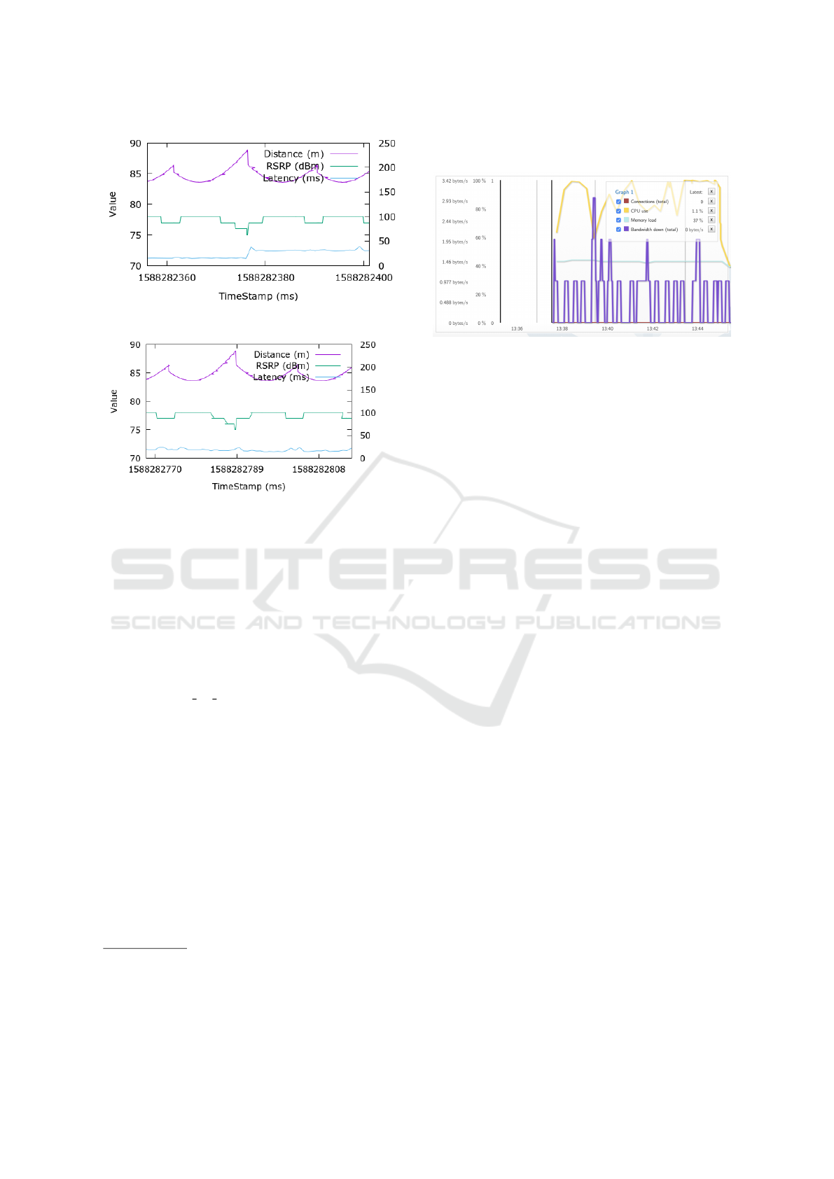
Figure 5: Roaming server requests.
Figure 6: Local server requests.
value is 24ms which is suitable for any common ser-
vice gaming or video watching. However, with roam-
ing, the ping gets a bit higher, around 30ms and the
maximum value is 54ms, it is acceptable for most
of games but there is a bit lag for a timing-critical
game and also live streaming video. Moreover, as
our experiment, the propagation delay in s8 will has
a noticeable effect only when the distance between
SGW from visited network and PGW from home net-
work is far enough since the delay is calculated by
distance/speed o f light
11
. In our model, we modify
the distance is 5000km, causing 0.016ms delay.
And after changing LTE network, in the case of
local server requests, the IP address of server is fixed
from the calls of UE, so we have to update the server
IP manually, in reality, it could affect user experience
and make them incontinence because the service is
not continuous.
6.2.2 Video Streaming
The video streaming application run on Firefox which
is packed in a Docker Image
12
and presents for a UE
screen. The video server comes from mist server
13
.
Mist server is lightweight, only 309MB in Docker
Image
14
, but really powerful to build a local video
11
https://www.space.com/15830-light-speed.html
12
https://hub.docker.com/r/jlesage/firefox
13
https://www.mistserver.org
14
https://hub.docker.com/r/r0gger/mistserver
streaming service, we stream a video via HTTP pro-
tocol.
Figure 7: Metric statistic in Mist server.
The mist server only supports basic statistics as
the CPU, memory usage, bandwidth up and down
metrics, so we can not evaluate the latency (see Figure
7). The graph shows that the simulator connection is
not stable when handover events occur both for Inter
and Intra, the CPU gets lower since the requests are
suspended for a while.
7 CONCLUSIONS
In this paper, we presented an extension of the LTE-
EPC module of the NS-3 simulator for a multi-
domain concept. Our work is based on technical doc-
uments about handover and roaming. All components
are encapsulated in Docker containers, which facil-
itates a flexible simulation system so it can be de-
ployed in any host without limitations (?), (?), (?).
Besides that, connecting the simulator with real ap-
plications as ping and video streaming shows a pos-
sibility of application extension and scalability with
multiple servers and UEs.
However, there are concerns we could extend for
our future work. The passing domain will change the
server IP, and UE by itself can not update easily, so
we need to extend our model with the concept of ser-
vice continuity to meet the needs of user experiments
for live services. Tested applications are still limited
since they do not support in-depth analysis. Thus,
we have to apply more application models and use
a statistic tool to investigate further.
Moreover, the 5G generation requires our system
to be upgradable and adaptable. Currently, we only
support to 4G network. With 5G, we could have a
wider space to improve but also challenges. In the
next version, we will try to add mmWave and gNB
(Noll and Chowdhury, 2011) into our model as the
starting point for 5G.
A Multi-domain Network Simulator based on NS-3
223

REFERENCES
Baldo, N., Requena-Esteso, M., Nin-Guerrero, J., and
Miozzo, M. (2012). A new model for the simulation
of the lte-epc data plane. Proc. of WNS3.
Behrisch, M., Bieker, L., Erdmann, J., and Krajzewicz, D.
(2011). SUMO - Simulation of Urban MObility - an
Overview. Proceedings of the 3rd International Con-
ference on Advances in System Simulation (SIMUL
2011), (October):63–68.
ETSI (2013). Home Subscriber Server (HSS)
diameter interfaces for interworking with
packet data networks and applications. URL:
https://www.etsi.org/deliver/etsi ts/129300 129399/
129336/11.01.00 60/ts 129336v110100p.pdf [ac-
cessed: 2020-27-02].
GSM (1997). Digital cellular telecommunications sys-
tem (Phase 2+); Handover procedures. URL:
https://www.etsi.org/deliver/etsi gts/03/0309/05.01.
00 60/gsmts 0309v050100p.pdf [accessed: 2020-17-
02].
Huawei (2020). LTE International Roaming Whitepaper.
URL: https://carrier.huawei.com/en/technical-topics/
core-network/lte-roaming-whitepaper [accessed:
2020-26-02].
Le, V. T., El Ioini, N., and Pahl, C. (2019). Blockchain
based service continuity in mobile edge comput-
ing. In 2019 Sixth International Conference on In-
ternet of Things: Systems, Management and Security
(IOTSMS), pages 136–141.
Noll, J. and Chowdhury, M. M. (2011). 5g: Service continu-
ity in heterogeneous environments. Wireless Personal
Communications, 57(3):413–429.
Page, J. K. and Dricot, J.-M. (2016). Software-defined net-
working for low-latency 5g core network. 2016 Inter-
national Conference on Military Communications and
Information Systems (ICMCIS), pages 1–7.
Piro, G., Baldo, N., and Miozzo, M. (2011). An lte mod-
ule for the ns-3 network simulator. In Proceedings of
the 4th International ICST Conference on Simulation
Tools and Techniques, pages 415–422. ICST (Institute
for Computer Sciences, Social-Informatics and . . . .
Portabales, A. R. and Nores, M. L. (2018). Dockemu: Ex-
tension of a scalable network simulation framework
based on docker and ns3 to cover iot scenarios. In
SIMULTECH, pages 175–182.
Princy, S. E. and Nigel, K. G. J. (2015). Implementation of
cloud server for real time data storage using raspberry
pi. In 2015 Online International Conference on Green
Engineering and Technologies (IC-GET), pages 1–4.
Quinlan, J. J., Raca, D., Zahran, A. H., Khalid, A., Ra-
makrishnan, K., and Sreenan, C. J. (2016). D-lite: A
platform for evaluating dash performance over a simu-
lated lte network. In 2016 IEEE International Sympo-
sium on Local and Metropolitan Area Networks (LAN-
MAN), pages 1–2. IEEE.
Research department (2012). Free speed survey. URL:
https://www.rsa.ie/Documents/Road%20Safety/
Speed/Speed survey 2011.pdf [accessed: 2020-25-
04].
Riley, G. F. and Henderson, T. R. (2010). The ns-3 network
simulator. In Modeling and tools for network simula-
tion, pages 15–34. Springer.
Sabbah, A., Jarwan, A., Al Shiab, I., Ibnkahla, M., and
Wang, M. (2018). Emulation of large-scale lte net-
works in ns-3 and core: A distributed approach.
Sommer, C., Yao, Z., German, R., and Dressler, F. (2008).
Simulating the influence of IVC on road traffic us-
ing bidirectionally coupled simulators. Proceedings
- IEEE INFOCOM, 00(c).
Tayyab, M., Gelabert, X., and J
¨
antti, R. (2019). A survey on
handover management: From lte to nr. IEEE Access,
7:118907–118930.
Varga, A. (2020). INETFramework - GitHub Repos-
itory. URL: https://github.com/inet-framework/inet
[accessed: 2020-02-22].
Varga, A. and Hornig, R. (2008). An overview of the om-
net++ simulation environment. In Proceedings of the
1st international conference on Simulation tools and
techniques for communications, networks and systems
& workshops, page 60. ICST.
Virdis, A., Stea, G., and Nardini, G. (2014). Simulte - a
modular system-level simulator for lte/lte-a networks
based on omnet++. pages 59–70.
SIMULTECH 2020 - 10th International Conference on Simulation and Modeling Methodologies, Technologies and Applications
224
