
Simu5G: A System-level Simulator for 5G Networks
Giovanni Nardini
1a
, Giovanni Stea
1b
, Antonio Virdis
1c
and Dario Sabella
2d
1
Dipartimento di Ingegneria dell’Informazione, University of Pisa, Pisa, Italy
2
Intel Deutschland GmbH, Neubiberg, Germany
Keywords: 5G, System-level Simulation, Discrete-event Simulation, OMNeT ++.
Abstract: This paper presents Simu5G, a new OMNeT++-based system-level simulator of 5G networks. Simu5G is built
starting from the SimuLTE simulation library, which models 4G (i.e., LTE/LTE-A) networks, and is compatible
with the latter, thus allowing the simulation of 4G-5G coexistence and transition scenarios. We discuss the mod-
elling of the protocol layers, network entities and functions, and validate our abstraction of the physical layer
using 3GPP-based scenarios. Moreover, we report profiling results related to Simu5G execution, and we describe
how it can be employed to evaluate Radio Access Network configurations, as well as end-to-end scenarios in-
volving communication and computation, e.g., with Multi-access Edge Computing applications.
1 INTRODUCTION
The fifth generation of cellular networks, known as 5G,
is expected to bring significant changes to the wireless
networking landscape. The advent of 5G systems, in
fact, will be one of the main pillars of a technology rev-
olution that will enable an unprecedented range of ICT
services, such as smart cities, autonomous vehicles,
augmented reality and Industry 4.0. Another, comple-
mentary pillar key technology that will benefit from the
introduction of 5G will be Multi-access Edge Compu-
ting (MEC), which will bring cloud-computing capa-
bilities to the edge of the network, allowing mobile us-
ers to capitalize the power of complex algorithms such
as those based on artificial intelligence. The new gen-
eration of networks, coupled with MEC, will thus wit-
ness a tight integration of computation and communi-
cation in a unified infrastructure.
The Radio Access Network (RAN) of the 5G net-
work is composed of base stations, known as gNodeBs
(gNB) according to the 3GPP terminology, which allo-
cate radio resources to a number of User Equipments
(UEs). The latter can be any device endowed with cel-
lular connectivity like, e.g., handheld devices, laptops,
home gateways, connected vehicles or industrial ma-
chines. The 5G New Radio (NR) technology is based
on the new radio access standard developed by the
a
https://orcid.org/0000-0001-9796-6378
b
https://orcid.org/0000-0001-5310-6763
c
https://orcid.org/0000-0002-0629-1078
d
https://orcid.org/0000-0002-8723-7726
3GPP. As far as the data plane is concerned, NR con-
sists of a stack of layered protocols, which closely re-
sembles that of 4G (LTE/LTE-Advanced) networks, to
favour the incremental deployment of 5G and its coex-
istence with the existing 4G infrastructure.
The performance evaluation of 5G networks is of
paramount importance, in at least two complementary
facets. On one hand, there is a strong need to devise
and validate resource management schemes for the 5G
RAN: for instance, scheduling algorithms at the gNB,
or the best partition of resources when dual-connectiv-
ity UEs are simultaneously connected to both a 4G and
a 5G base station. The fact that the deployment of 5G
is underway as we write, and that the above functions
will mostly be realized in software, makes this all the
more compelling. On the other hand, there is an even
stronger need to assess the feasibility and performance
of new-generation, 5G-based services. Several of
these, such as autonomous driving or factory automa-
tion, will be latency-critical, and changes in the net-
work configuration or deployment may have a drastic
impact on their timing properties.
Both the above endeavours, which are clearly inter-
twined, call for a flexible system-level simulation tool,
where the protocols, functions and entities of the 5G
NR system are modelled in detail, following the cur-
rent 3GPP standards, while still working at a packet
68
Nardini, G., Stea, G., Virdis, A. and Sabella, D.
Simu5G: A System-level Simulator for 5G Networks.
DOI: 10.5220/0009826400680080
In Proceedings of the 10th International Conference on Simulation and Modeling Methodologies, Technologies and Applications (SIMULTECH 2020), pages 68-80
ISBN: 978-989-758-444-2
Copyright
c
2020 by SCITEPRESS – Science and Technology Publications, Lda. All rights reserved

level. There is a substantial paucity of such tools in the
academic community. To the best of our knowledge,
there are few existing system-level 5G simulators. 5G-
LENA (Patriciello, 2019), based on ns3
1
is an evolu-
tion of the LENA simulator (Baldo, 2011) and the
mmWave simulation module from ns3. It is focused on
the simulation of MAC and PHY layer of NR and pro-
vides tools for the evaluation of Bandwidth Parts man-
agement. However, it does not model dual-connectiv-
ity scenarios or configurations with coexisting LTE-
Advanced and 5G networks. There are also other 5G
simulators, notably 5GK-Simulator
2
, Vienna 5G SL
simulator (Müller et al, 2018) and WiSE (Jao et al,
2018). These model the MAC layer and the physical
link to a high level of fidelity, so that users can test
(e.g.) new transmission and decoding schemes. The
purpose of a system-level simulator is fundamentally
different, i.e., to allow the testing of end-to-end ser-
vices and scenarios, possibly at a large scale, including
layer-3, layer-4, and application-layer protocols and
logic. Some of the above tools do provide a system-
level execution mode, which allows simulating link-
level aspects on a large scale, by introducing simplifi-
cation in modelling while significantly increasing exe-
cution efficiency. However, none of them simulate ap-
plication packets flowing through the network.
In this paper, we present Simu5G
3
, a new 5G sim-
ulator based on the well-known SimuLTE library
(Virdis et al, 2014, 2015, 2019), used by industry and
academia. Simu5G is based on the OMNeT++ simula-
tion framework, and provides a collection of models
with well-defined interfaces, which can be instantiated
and connected to build arbitrarily complex simulation
scenarios. Simu5G incorporates all the models from
the INET library, which allows one to simulate generic
TCP/IP networks including 5G NR layer-2 interfaces.
In particular, Simu5G simulates the data plane of the
5G RAN (rel. 16) and core network. It allows simula-
tion of 5G communications in both Frequency Division
Duplexing (FDD) and Time Division Duplexing
(TDD) modes, with heterogeneous gNBs (macro, mi-
cro, pico etc.), possibly communicating via the X2 in-
terface to support handover and inter-cell interference
coordination. Dual connectivity between an eNB (LTE
base station) and a gNB (5G NR base station) is also
available. 3GPP-compliant protocol layers are pro-
vided, whereas the physical layer is modelled via real-
istic, customizable channel models. Resource schedul-
ing in both uplink and downlink directions is sup-
ported, with support for Carrier Aggregation and mul-
tiple numerologies, as specified by the 3GPP standard
1
https://www.nsnam.org/, last accessed April 2020.
2
http://5gopenplatform.org, last accessed on April 2020.
(3GPP TR 38.300, TR 38.211). Simu5G supports a
large variety of models for mobility of UEs, including
vehicular mobility.
Simu5G allows one to code and test, for instance,
resource allocation and management schemes in 5G
networks, e.g. selecting which UEs to target, using
which modulation scheme, etc., taking into account in-
ter-cell interference coordination, carrier selection, en-
ergy efficiency and so on. Moreover, it allows one to
instantiate scenarios where a user application, running
at the UE, communicates with a MEC application re-
siding at a MEC host (Nardini et al, 2018), to evaluate
(e.g.) the round-trip latency of a new-generation ser-
vice, inclusive of the computation time at the MEC
host. More to the point, Simu5G can run in real-time
emulation mode, enabling interaction with real de-
vices. In fact, on one hand OMNeT++ allows real-time
scheduling of events; on the other hand, the INET li-
brary allows can be configured so as to exchange IP
packets between local applications or network inter-
faces and the simulator. These IP packets are processed
by the simulator as if they were traversing the 5G cel-
lular network. The above two features concur to allow
a user to run live networked applications having an em-
ulated 5G network in the middle, using the same code-
base for both simulations and live prototyping, which
abates the developing time and makes results more re-
liable and easier to demonstrate.
The rest of the paper is organized as follows. Sec-
tion 2 briefly reviews the OMNeT++ framework and
the SimuLTE library. Section 3 describes Simu5G. Its
validation is described in Section 4, whereas Section 5
shows profiling results and the performance evaluation
of two exemplary simulation scenarios. Section 6 con-
cludes the paper and outlines future work.
2 BACKGROUND
This section introduces basic notions of cellular net-
works, then it describes the OMNeT++ simulation
framework and the INET library, and finally the Sim-
uLTE library, on which Simu5G is built.
2.1 An Overview of Cellular Networks
In this section we provide enough background for a
reader to understand the modelling concepts described
in the rest of this paper. The basic concepts underlying
are common to both 4G (LTE) and 5G (NR) cellular
networks, as standardized by the 3GPP. For this rea-
3
http://simu5g.org/, last accessed on April 2020.
Simu5G: A System-level Simulator for 5G Networks
69

BS
PGW
Internet
UE
CoreNetwork
RAN
Figure 1: Architecture of a cellular network.
son, we will describe the concepts without specific ref-
erence to either standard.
A cellular network consists of a RAN and a Core
Network, as shown in Figure 1. The RAN is composed
of cells, under the control of a single base station (BS).
UEs are attached to a BS and can change the serving
BS through a handover procedure. BSs communicate
with each other through the X2 interface, a logical con-
nection which normally runs on a wired network. The
Core Network consists of IP routers connecting an en-
try point, the Packet GateWay (PGW) to the BSs. For-
warding in the Core Network is carried out using the
GPRS tunneling protocol (GTP).
In the RAN, communications between the BS and
the UE occur at layer 2 of the OSI reference model.
Layer 1 and 2 are implemented using a stack of four
protocols, on both the BS and the UE. From the top
down, we first find the Packet Data Convergence Pro-
tocol (PDCP), which receives IP datagrams, performs
cyphering and numbering, and sends them to the Radio
Link Control (RLC) layer. RLC Service Data Units
(SDUs) are stored in the RLC buffer, and they are
fetched by the underlying MAC (Media Access Con-
trol) layer when the latter needs to compose a transmis-
sion. The MAC assembles the RLC Protocol Data
Units (PDUs) into Transport Blocks (TBs), adds a
MAC header, and sends everything through the physi-
cal (PHY) layer for transmission.
Resources scheduling is done by the BS periodi-
cally, every Transmission Time Interval (TTI). On
each TTI the BS allocates a vector of Resource Blocks
(RBs) to backlogged UEs, according to its scheduling
policy. A TB occupies a variable number of RBs, based
on the Modulation and Coding Scheme (MCS) chosen
for transmission. The MCS is selected by the BS, based
on the Channel Quality Indicator (CQI) reported by the
UE. The latter mirrors the Signal to Interference to
Noise Ratio (SINR) perceived by the UE, quantized
over a scale of 0 (i.e., very poor) to 15 (i.e., optimal).
The CQI implicitly selects the MCS, hence the number
of bits that one RB can carry.
In the downlink (DL), the BS transmits the TB to
the scheduled UEs on the allocated RBs. In the uplink
(UL), the BS sends transmission grants to UEs, speci-
fying which RBs and MCS to use. UEs signal to the BS
4
http://omnetpp.org, last accessed March 2020
Compoundmodule
Simplemodule2 Simplemodule3
Simp lemodule1
gates
connections
Figure 2: OMNeT++ module connection.
that they have UL backlog by sending Buffer Status
Reports (BSRs) after a scheduled transmission, or by
starting a Random ACcess (RAC) procedure in order
to obtain a scheduling grant by the BS, if they are not
scheduled. Scheduling and transmissions in the UL and
DL directions are independent. The partitioning be-
tween UL and DL resources can be in frequency or
time, leading to Frequency-division Duplexing (FDD)
and Time-division Duplexing (TDD) deployments. In
FDD, each direction uses a separate spectrum. In TDD,
instead, the DL and UL legs share the same spectrum,
and the two directions coexist alternating over time.
MAC transmissions in both directions are pro-
tected by a Hybrid-Automatic Repeat Requests. After
a configurable number of TTIs, the receiver sends an
ACK/NACK to the sender, which can then re-schedule
a failed transmission. H-ARQ can be synchronous or
asynchronous. In the first one, re-transmissions occur
after a fixed number of TTIs, whereas no such con-
straints exist in the second case.
2.2 The OMNeT++ Framework and the
INET Library
OMNeT++
4
is a well-known discrete-event simulation
framework that can be used to model practically any
kind of networks, including wired, wireless, on-chip
networks, sensors networks, photonics networks, etc.
Its main building blocks are modules, which can be ei-
ther simple or compound. Modules exchange messages
through connections linking their gates, which act as
interfaces. A network is a special compound module,
with no gates to the outside world, which sits at the top
of the hierarchy. Connections must respect module hi-
erarchy: with reference to Figure 2, simple module 3
cannot connect to 2 directly, but must instead pass
through the compound module gate. Simple modules
implement model behavior via event handlers, called
by the simulation kernel on receipt of messages. For
instance, a node can schedule a timer by sending a mes-
sage to itself. Simple modules have an initialization
and finalization function, that can be called in user-de-
fined order at the start and the end of a simulation.
OMNeT++ separates a model’s behavior, descrip-
tion and parameter values. The behavior is coded in
SIMULTECH 2020 - 10th International Conference on Simulation and Modeling Methodologies, Technologies and Applications
70

C++. The description (i.e., gates, connections and pa-
rameter definition) is expressed in files written in Net-
work Description (NED) language. Parameter values
are written in initialization (INI) files. NED is a declar-
ative language, which exploits inheritance and inter-
faces, and it is fully convertible into XML. NED allows
one to write parametric topologies, e.g. rings or trees
of variable size. NED files can be edited both textually
and through a GUI. INI files contain the parameter val-
ues that will be used to initialize the model. Multiple
values or intervals can be specified for a parameter.
OMNeT++ Eclipse-based IDE facilitates debug-
ging by allowing a user to inspect modules, turn on/off
textual output during execution, visualizing the mes-
sage flow in an animation, and displaying events on a
time chart. OMNeT++ studies are generated from INI
files, computing the Cartesian product of all the param-
eter values and generating independent replicas with
different seeds for the random number generators.
Multiple runs can be executed in parallel on a multicore
machine. Rule-based data analysis allows a user to
construct recipes to filter or aggregate data, which can
then be applied to selected data files or folders.
INET
5
is a model library for OMNeT++. It imple-
ments models of many components of a communica-
tion network, such as communication protocols, net-
work nodes, connections, etc. INET contains models
for the Internet stack (TCP, UDP, IPv4, IPv6, OSPF,
BGP, etc.), wired and wireless link layer protocols
(Ethernet, PPP, IEEE 802.11, etc.), and provides sup-
port for developing custom mobility models, QoS ar-
chitectures, etc.
Thanks to OMNeT++ modular structure, by incor-
porating the INET library a user can instantiate and
connect protocol layers (e.g., an entire TCP/IP stack at
a host, from the application to the MAC), and to
quickly setup composite models, e.g., an IP router with
an Ethernet card and a PPP WAN connection.
To allow emulation of real-life applications and
protocols, INET provides modules that act as a bridge
between the simulation environment and the real net-
work interfaces in the host operating system. Packets
received by the real interfaces appear in the simulation
within such modules, whereas simulated packets sent
to the latter are sent out on the real network interface.
Emulation requires OMNeT++ to be configured with a
real-time event scheduler synchronized with the sys-
tem clock.
2.3 SimuLTE
SimuLTE is a popular simulation library built on OM
5
http://inet.omnetpp.org, last accessed March 2020
LteNi cUe
IP
TCP UDP
TCP
TCP
TCP
APPS
TCP
TCP
UDP
APPS
Ue
LteNi cEnb
IP
X2AP
eNodeB
PPP
GTP
X2PPP
SCTP UDP
Binder
PGW
UDP
PPP
IP
GTP
PPP
Figure 3: Main components of SimuLTE.
NeT++. Since its publication in 2014, it has supported
more than 90 published research works
6
.
SimuLTE simulates the data plane of the
LTE/LTE-A RAN and Core Network. Its main compo-
nent nodes are shown in Figure 3. UEs and BSs (called
eNBs in LTE) are implemented as compound modules,
that can be connected with each other and with other
nodes (e.g. routers, applications, etc.) to compose net-
works. Both have an LTE Network Interface Card
(NIC) module, which implements the LTE protocol
stack. The Ue module also includes IP and TCP/UDP
protocols, as well as vectors of TCP/UDP applications.
The eNodeB module includes two PPP interfaces: the
X2PPP module allows the direct connection with
neighbouring eNBs using the Stream Control Trans-
mission Protocol (SCTP) protocol as specified by the
standard, whereas the PPP module is connected to the
PGW module.
SimuLTE simulates the data plane. Signalling and
management protocols are not implemented in the cur-
rent version (but they can easily be added). Control-
plane interactions are instead modelled by adding a
Binder module, which is visible from the other nodes
and stores information about them (e.g., which node
uses which resource frequency when). Control-plane
interactions can then be easily modelled via queries to
the Binder, without the need of complex logic.
The NIC module models all the sublayers of the
LTE stack described in Section 2.2, each as a simple
module. One aspect of interest is that SimuLTE models
the tangible effects of propagation on the wireless
channel at the receiver without modelling symbol
transmission and constellations in the PHY. With ref-
erence to Figure 4, when a MAC PDU is sent from a
sender to a receiver, an OMNeT++ message is ex-
changed between them. On receipt of the latter, the re-
ceiver applies a channel model to compute the received
power. The channel model can be configured to incor-
porate fading, shadowing, pathloss, etc., and can be
made arbitrarily complex. From the received power,
the receiver computes the SINR, querying the Binder
to know which other nodes were interfering on the
6
Google scholar search, February 2020.
Simu5G: A System-level Simulator for 5G Networks
71
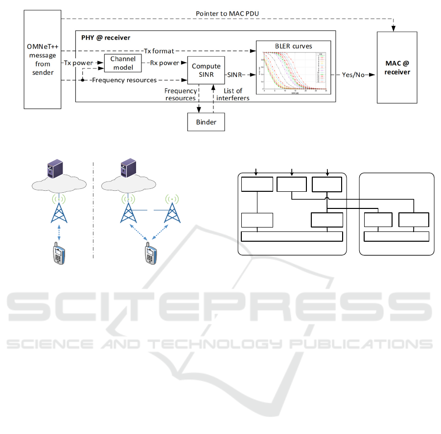
Figure 4: Block diagram of the modelling of the LTE physical layer within SimuLTE.
gNB
gNBeNB
X2
UE
UE
EPCEPC
PGW PGW
Figure 5: SA (left) and ENDC (right) deployment.
same resources. Then, it leverages Block Error Rate
(BLER) curves to compute the reception probability
for each RB composing the ongoing transmission.
BLER curves can be obtained from a link-level simu-
lator. This makes it possible to translate a SINR and a
transmission format to a probability of correct recep-
tion of the entire MAC PDU (some straightforward
probability algebra is required if a MAC PDU occupies
more than one RB). The above modelling abates the
computational complexity of the decoding operation,
hence the simulation running time, while preserving its
correctness, and it still allows arbitrary channel models
to be used. As we show in the next section, the same
modelling philosophy is preserved in Simu5G.
3 MODELING 5G NEW-RADIO
COMMUNICATIONS
The main components of Simu5G are the NrUe and
gNodeB modules, obtained as extensions of the Ue and
eNodeB modules described in Section 2.3. They main-
tain the same architecture shown in Figure 3, except for
the LteNic modules that are replaced with their NR ver-
sions, called NrNicUe and NrNicGnb, respectively. We
underline that this architectural choice allowed us to
incorporate functionalities modelled in SimuLTE into
Figure 6: Interactions between eNB and gNB in an ENDC
deployment.
Simu5G at no cost. These include, among others, UE
handover and network-controlled device-to-device
(D2D) communications, both one-to-one and one-to-
many. Since these were described in recent standalone
papers, they will not be mentioned further here.
In a typical network setting, the gNB is connected
to the PGW to communicate with the Internet, as
shown in Figure 5 (left). This is referred as StandAlone
(SA) deployment. However, the 3GPP standard de-
fines an E-UTRA/NR Dual Connectivity (ENDC) de-
ployment, shown in Figure 5 (right), where LTE and
5G coexist (3GPP – TR 38.801). This option is of in-
terest especially in the early development phases of 5G.
In this configuration, the gNB works as a Secondary
Node (SN) for an LTE eNB, which acts as Master
Node (MN) and is connected to the Core Network. The
eNB and the gNB are connected through the X2 inter-
face and all NR traffic needs to go through the eNB.
According to (3GPP - TR 37.340), the data flow be-
tween the eNB and the gNB is shown in Figure 6. With
reference to the latter, data destined to a UE served by
the eNB (Master Cell Group – MCG - bearer) follows
the LTE protocol stack, whereas data destined to a UE
served by the gNB (Secondary Cell Group – SCG -
bearer) gets into the NR PDCP entity at the eNB and is
transferred to its peering NR RLC entity in the gNB,
via the X2 interface. The 3GPP standard also supports
Split Bearers (SBs). With this feature, data belonging
gNB
NR RLC
entity
NR MAC
LTE PDCP
entity
LTE RLC
entity
NR PDCP
entity
LTE MAC
MCG
Bearer
Split
Bearer
LTE RLC
entity
X2
SCG
Bearer
NR PDCP
entity
NR RLC
entity
eNB
SIMULTECH 2020 - 10th International Conference on Simulation and Modeling Methodologies, Technologies and Applications
72

Figure 7: Structure of the NR NIC modules.
Table 1: NR numerologies.
𝜇 0 1 2 3 4
TTI (ms) 1 0.5 0.25 0.125 0.0625
to the same connection can traverse either the eNB or
the gNB. The PDCP layer at the UE side will then re-
order PDUs coming from LTE/NR RLC layers.
Simu5G allows one to deploy networks in both SA
and ENDC configurations. In our modelling, the inter-
nal structure of the NRNicGnb module is shown in Fig-
ure 7 (left). It is composed of one submodule for each
layer of the protocol stack, plus one Ip2Lte module that
acts as a bridge with the IP layer. Data packets can be
received from either the PGW through the Ip2Lte mod-
ule or its master eNB through the X2Manager module
in ENDC scenarios. Figure 7 (right) shows the NrNi-
cUe module, which is equipped with two sets of PHY,
MAC and RLC submodules to enable coexistence of
NR and LTE. The NR versions of the layers are used
for processing data coming from/going to the gNB,
whereas the LTE ones are used for processing data
coming from/going to the eNB, if any. As shown in the
figure, the PDCP layer is unique. This way, packets be-
longing to a SB are handled by the same PDCP entity,
which provides in-sequence delivery to upper layers.
3.1 NR Resource Management
NR communications can take place on several fre-
quency carrier components (CCs), i.e., disjoint por-
tions of frequency. Each CC has a number of RBs.
Each e/gNB may implement multiple CCs, each char-
acterized by its own carrier frequency, in the so-called
Carrier Aggregation (CA) mechanism. To support
CA, we modeled a carrierAggregation module to store
all the information related to the CCs employed in the
network. Like the Binder, it is modelled as global mod-
ule visible by all e/gNBs and UEs in the simulation. It
includes a vector of 𝑁 componentCarrier submodules,
whose carrier frequency can be configured via
NED/INI. However, we need to take into account that
e/gNBs and UEs might have limited capabilities in
terms of supported frequency range, hence a gNB/UE
Figure 8: Example of UEs’ capabilities.
D D D D D D F F U U U U U U
D D D D D D D D D D F F U U
slotduration
symbolduration
Figure 9: Examples of TDD slot formats.
may be able to use only a subset of the available CCs.
As a result, a UE can be attached to an e/gNB only if
the latter supports at least one of the CCs supported by
the UE itself. The e/gNB, in turn, can schedule a UE in
a given CC only if the UE supports that CC.
As with LTE, a NR radio frame is 10 ms long and
consists of 10 subframes, each having 1ms duration.
However, NR subframes are further divided into up to
14 slots, which are the NR TTIs, A numerology index
𝜇 defines the slot duration, as shown in Table 1. UEs
are scheduled in slots. Supporting multiple numerolo-
gies allows a network to handle services with different
QoS requirements. In our model, a different 𝜇 can be
associated to each CC. Each componentCarrier mod-
ule has its own parameter 𝜇 that can be configured via
NED/INI. gNBs and UEs might support only a subset
of numerologies, which constrains resource allocation.
The example in Figure 8 shows a gNB supporting three
CCs that employ different carrier frequencies and nu-
merologies. The gNB serves UE1 and UE2, which
have different capabilities in terms of supported fre-
quencies and numerologies, as shown in the figure. For
instance, UE1 only supports µ3, whereas UE2 sup-
ports frequencies below 6GHz. According to that con-
figuration, UE1 can be served by the gNB using CC0
and CC1, whereas UE 2 can be served by the gNB us-
ing CC 0 and CC 2.
Simu5G supports both FDD and TDD. In FDD,
each CC has separate portions for UL and DL spectra.
NR TDD allows one to choose among 62 possible slot
formats (3GPP - TR 38.213), where individual sym-
bols in a slot can be DL, UL or flexible. Examples of
slot formats are shown in Figure 9. Flexible symbols
can be assigned dynamically to either DL or UL trans-
missions, or kept idle as a guard interval to minimize
the DL/UL interference. In TDD, the number of bytes
that can be transmitted to/by a UE in a slot is therefore
NrNicGnb
NrPhy
Ip2Lte
X2Manager
NrRlc
NrMac
NrPdcp
Channel
Model
NrNicUe
LtePhy
Ip2Lte
LteRlc
LteMac
NrPdcp
Channel
Model
NrPhy
NrRlc
NrMac
gNB
UE1
UE2
CC0,f=700MHz,µ=0
CC1,f=2GHz,µ=2
CC2,f=30GHz,µ=4
UE1
UE2
f
µ
<6GHz
‐<3
‐
Simu5G: A System-level Simulator for 5G Networks
73

Figure 10: Pseudocode for the scheduling procedure.
smaller, since a smaller number of symbols is used. As
we explain later in Section 3.3, this affects the compu-
tation of the TB Size (TBS) at the MAC level.
We model TDD slot formats as properties of the
CC: this means that all gNBs using a CC will use the
same slot format on it. Accordingly, we associate the
slot format to the componentCarrier submodules. This
greatly simplifies interference management, since it
guarantees that DL and UL symbols can never interfere
with each other. Therefore, their arrangement within a
slot is immaterial, the only relevant information being
their total number. We thus model a slot format as a
triplet of integers
〈
𝑛
,𝑛
,𝑛
〉
, representing the
number of DL, UL and flexible symbols, respectively.
Their sum must be equal to the total number of symbols
within a slot (i.e., 14). In the current version of
Simu5G, flexible symbols can only be used as guard
symbols. However, the above modeling allows one to
easily design policies to assign flexible symbols to DL
or UL dynamically.
3.2 PDCP and RLC Layers
We implemented a NrPdcp module as an extension of
the LtePdcp module, to handle ENDC. The NrPdcp
module is instantiated within the NIC of either a gNB
or an eNB acting as MN in an ENDC setting. In the
latter case, packets arriving from the upper layers need
to be forwarded to either the eNB’s RLC, or to the gNB
acting as SN. To achieve this, each packet is marked
before entering the PDCP layer, i.e. at the Ip2Lte mod-
ule. The NrPdcp entity then redirects packets towards
the RLC layer of either the eNB or the gNB via the X2
interface accordingly. The marking policy works at the
packet level (rather than at the connection level), al-
lowing finer granularity and dynamic management of
SB functionalities. Moreover, it is user configurable,
which allows a user to design and evaluate, e.g., load-
balancing policies. The functionalities of the NR RLC
layer are the same as LTE’s, hence the NrRlc module
is the same as the SimuLTE’s LteRlc module.
3.3 MAC Layer
The MAC layer runs periodically, on each TTI. Multi-
ple CCs may employ different numerologies, hence
different TTI durations. However, TTI durations 𝑇
are
multiple of each other (see Table 1), hence we schedule
MAC procedures at a period 𝑇min
𝑇
. At any
scheduling epoch t, the MAC performs operations only
for CCs 𝑖 s.t. 𝑡 𝑚𝑜𝑑 𝑇
0. Accordingly, a gNB runs
an independent scheduler per CC.
gNB scheduling consists in allocating a vector or
RBs to UEs. The pseudocode in Figure 10 shows an
example of a scheduling procedure, which takes as in-
put the set 𝑄 of backlogged UEs, then it allocates one
CC at a time, e.g. starting from CC 0. For each CC 𝑖,
the scheduler considers 𝑈
, i.e. the set of UEs that can
use CC 𝑖 , to obtain 𝑄
⊆𝑄, which includes back-
logged UEs schedulable on CC 𝑖. Then, the scheduling
routine sorts 𝑄
according to a given policy (e.g.
MaxC/I or PF) and scans it to allocate RBs to UEs. The
scheduling routine produces a schedule list 𝑆
, includ-
ing the set of UEs allocated on CC 𝑖. UEs which clear
their backlog are removed from 𝑄, so that subsequent
CCs will not consider them. With this approach, CCs
are scanned in sequence, with no attempt to balance the
load among CCs, minimize the number of active CCs,
or schedule UEs where they perceive, e.g., the best
SINR. However, a user can easily define a scheduler
that achieves the above objectives by modifying the
procedure in Figure 10. Optimal cross-CC scheduling
policies can also be envisaged, possibly using external
optimization solvers like IBM CPLEX.
After scheduling each CC, the scheduler obtains
the global schedule list 𝑆∪
𝑆
. For each element of
𝑆, the MAC layer builds a MAC Transport Block (TB)
(in the DL) or issues a scheduling grant (in the UL).
The TBS depends on both the number of allocated RBs
and the CQI reported by the UE. The NrAmc C++ class
determines the TBS according to the procedure defined
in (3GPP - TR 38.214). According to the formulas in
(3GPP - TR 38.214), the TBS is also a function of the
number of DL(UL) symbols in the slot. When TDD is
employed, the number of available symbols is defined
by the slot format. The NrAmc class supports the ex
componentCarrier[0]
componentCarrier[1]
CarrierAggregation
channelModel[0]
channelModel[1]
channelModel[0]
channelModel[1]
channelModel[0]
UE1
UE2
gNB
Figure 11: Example of CA configuration.
1 Q = set of backlogged UEs
2 for each CC i active in this period
3 U_i = set of UEs allowed to use
CC i
4 Q_i = Q & U_i
5 S_i = scheduling(Q_i)
6 update Q
7 end for
8 S = U{S i}
SIMULTECH 2020 - 10th International Conference on Simulation and Modeling Methodologies, Technologies and Applications
74
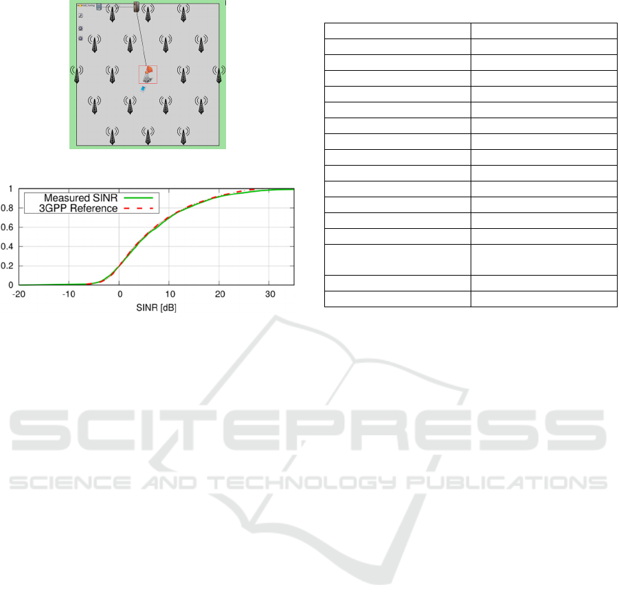
Figure 12: Simulation scenario.
Figure 13: Measured SINR.
tended MCS table with higher modulation orders, i.e.
up to the 256QAM modulation (3GPP - TR 38.214).
As far as H-ARQ is concerned, SimuLTE models
one HarqBuffer for each UE, including a number
(eight) of H-ARQ processes. Since every CC has its in-
dependent H-ARQ processes (3GPP - TR 38.300), we
extended this model by adding a data structure (e.g. a
map) that stores the set of HarqBuffers for every CC.
Once a MAC TB has been created, it is inserted into
the correct process included in its HarqBuffer corre-
sponding to the CC in which the TB has been sched-
uled. Simu5G supports flexible timing for the NR H-
ARQ feedback, which is asynchronous and can be con-
figured from the NED/INI file.
3.4 PHY Layer
The architecture of the PHY module in Simu5G mir-
rors the one in SimuLTE, shown in Figure 4. Each
MAC TB is encapsulated within an AirFrame message
and sent to the destination module, which applies the
model of the air channel to decide whether the Air-
Frame is received successfully or not. Since a MAC TB
is associated with a given CC, the corresponding Air-
Frame is subjected to channel effects (e.g. path loss,
shadowing etc.) that depend on that CC. This means
that different channel models have to be applied to
compute the SINR at the receiving side. For this rea-
son, each gNB/UE is equipped with a vector of chan-
nelModel modules, as shown in Figure 7 and each of
them is associated with one of the CCs available in the
Table 2: Main simulation parameters.
Parameter Name Value
#BSs 57
Inter-site Distance 500 m
#UEs 30 (uniform distribution)
Carrier frequency 700 MHz
Bandwidth 10 MHz (50 PRBs)
Fading + shadowing Enabled
BS Tx Power 46 dBm
BS antenna gain 8 dBi
BS noise figure 5 dB
UE antenna gain 0 dBi
UE noise figure 7 dB
Path loss model (3GPP - TR 36.873)
Load of interfering BSs 100% (Full buffer)
UE speed 3 km/h (80% indoor, 20%
indoor)
Traffic type CBR (240 kbps)
# of repetitions 50
carrierAggregation module. Figure 11 shows an ex-
ample of such association, where the carrierAggrega-
tion module implements two CCs, whose indexes in
the componentCarrier vector are 0 and 1, respectively.
The gNB and UE1 are configured to use both CCs,
hence they have two channel models, associated with
the two CCs. UE2, instead, is configured with one
channel model only associated with CC 1. Each trans-
mitted AirFrame includes a control field specifying the
CC it is transmitted onto, thus enabling the receiver to
process it via the relevant channelModel module.
The PHY layer interacts with the channelModel
modules via getSinr() end error() functions,
which compute the SINR and check if the airframe is
correctly decoded, respectively. The latter are the func-
tions that need to be redefined when implementing a
new channel model.
Simu5G comes with a default channel model called
Realistic Channel Model, which is compliant with the
3D model described in (3GPP - TR 36.873). The SINR
is computed on a per-RB basis as 𝑆𝐼𝑁𝑅
𝑃
∑
𝑃
𝑅
⁄
, where 𝑃
is the received signal
power, 𝑃
is the power received from the 𝑖-th inter-
ferer and 𝑅 is the Gaussian noise. When computing in-
ter-cell interference, only transmissions occurring on
the same CC are considered. For each RB 𝑖 occupied
by an AirFrame, the error() function obtains an er-
ror probability 𝑃
from the received SINR by using
the BLER curve related to the CQI used for transmis-
sion. Then, a uniform random variable 𝑋∈0;1 is
sampled and the AirFrame is assumed to be corrupted
if 𝑋 1
∏
1𝑃
, and correct otherwise.
Simu5G: A System-level Simulator for 5G Networks
75
a) ∆=0dB b) ∆=3dB
c) ∆=5dB d) ∆=7dB
Figure 14: BLER curves.
4 VALIDATION
In this section we show the results of the calibration of
SimuLTE BLER curves. The calibration followed the
guidelines reported by the 3GPP document (3GPP -
RP-180524). In particular, we refer to the Urban Macro
(UMa) scenario described in Table 4, config. A of the
above document.
With reference to Figure 12, we simulated 57 cells
deployed according to a regular hexagonal tessellation,
whose inter-site distance is 500 m. Each site hosts three
cells, radiating outwards according to the horizontal
and vertical pattern described in (3GPP - RP-180524).
We collect statistics only from the central site (three
central cells), whereas the other cells only produce in-
terference (occupying the whole spectrum). We ran-
domly deploy 30 UEs in the three central hexagons,
which attach to the cell from which they perceive the
best SINR. 80% of UEs are assumed to be indoor, 20%
outdoor. We assume DL traffic only and each UE re-
ceives a 240kbps Constant Bit Rate (CBR) traffic. The
values in the following charts are obtained by averag-
ing statistics from 50 independent repetitions, with
95% confidence intervals. The main simulation param-
eters are summarized in Table 1. Figure 13 shows that
the Cumulative Distribution Function (CDF) of the
SINR measured by UEs in the scenario described
above overlaps the CDF of the SINR obtained by the
calibration performed by 3GPP members and reported
as attachment of (3GPP - RP-180524).
Figure 15: Average error rate
after 1st TX attempt.
Figure 16: CDF of error rate
after 1st TX attempt.
Figure 17: Average number
of HARQ TX attempts.
Figure 18: CDF of the num-
ber of HARQ TX attempts.
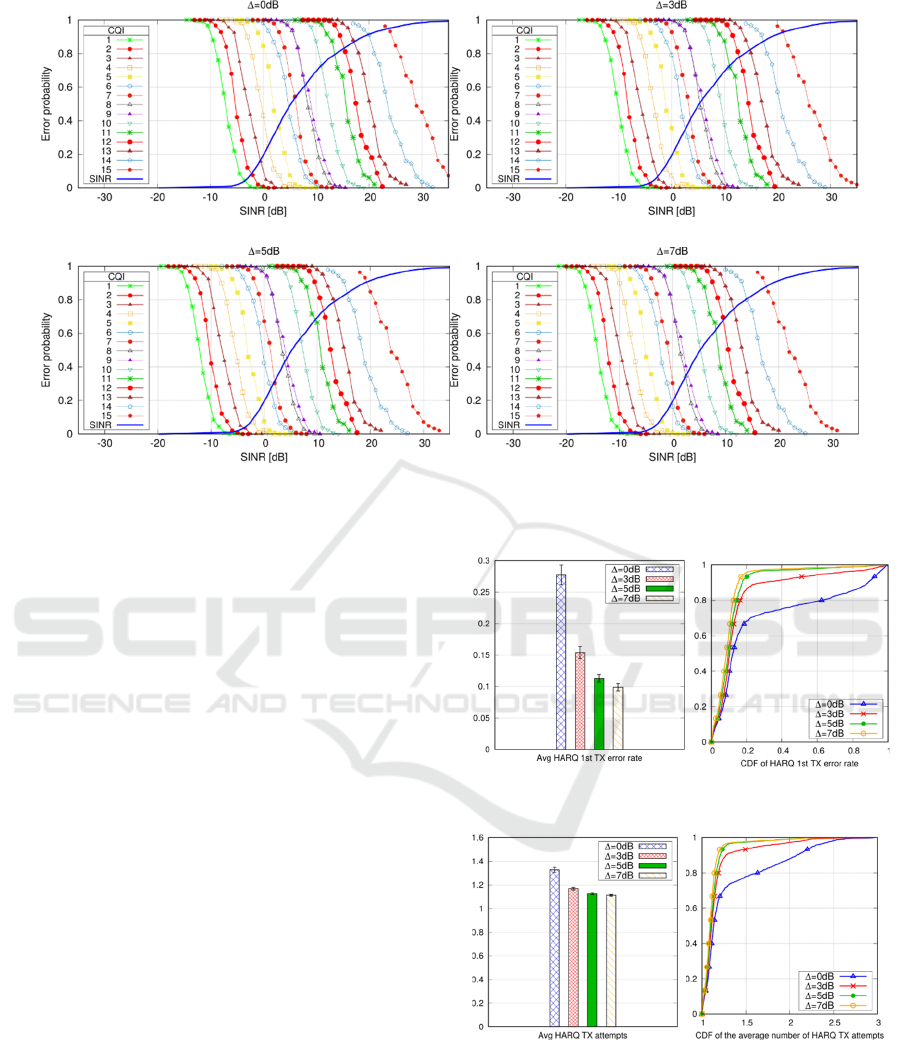
The successful reception of a MAC TB is evaluated us-
ing BLER curves, which link a SINR value to the error
probability according to the given MCS/CQI. Figure
14(a) shows the BLER curves obtained from link-level
simulations carried out with the Vienna LTE-A simu-
lator (Mehlfuerer et al., 2009). Such curves represent
SIMULTECH 2020 - 10th International Conference on Simulation and Modeling Methodologies, Technologies and Applications
76

Figure 19: Average loss of MAC TBs. Figure 20: CDF of loss of MAC TBs. Figure 21: CDF of app-level throughput.
Figure 22: Execution time with increasing CCs.
the error probability for a transmission occupying one
RB. Since 3GPP recommends a target TB error rate of
10%, we carried out simulations with different versions
of the BLER curves, i.e. shifted by a parameter ∆,
which models the improvement in the sensitivity of a
5G receiver, in order to determine the curves that allow
us to meet that target. The BLER curves obtained with
∆=3, 5, 7 dB are shown in Figure 14(b), (c) and (d),
respectively, and they are useful to observe what CQI
must be used by a UE to obtain a 10% TB error rate,
given its SINR. The figures also include the CDF of the
SINR measured by UEs in the above scenario for better
comparison.
Figure 15 reports the average error rate for the first
transmission attempt of TBs, i.e. the probability that
the first transmission of a MAC TB is not decoded cor-
rectly. The employed shift increases from left to right.
We observe that the rate is close to the target 10% error
rate when a shift of either ∆=5dB or ∆=7dB are used.
Figure 16 shows the CDF of the error rate for the
first H-ARQ transmission attempt, where we observe
that the target 10% error rate is around the median
value, whereas only a small fraction of UEs (i.e. ~5%)
gets an error rate larger than 20% when ∆=5dB or
∆=7dB are employed. Figure 17 and Figure 18 report
the average and the CDF of the number of H-ARQ
transmission attempts to successfully decode a MAC
TB. As expected, we obtain values close to 1. With
∆=5dB or ∆=7dB, the CDF shows that 95% of UEs
need less than 1.26 transmissions.
In some cases, four H-ARQ transmissions (the
maximum allowed) are not sufficient to correctly de
Figure 23: Execution time with increasing μ.
code a TB. In those cases, the TB is considered lost.
Figure 19 shows the average loss rate for a MAC TB.
With ∆=5dB and ∆=7dB, the residual loss rate is 0.8%
and 0.3%, respectively. Figure 20 reports the CDF of
the same metric, where we observe that around 95% of
UEs experiences no TB losses when ∆=5dB and
∆=7dB are used. The resulting application-level
throughput is shown in Figure 21. Also in this case
∆=5dB and ∆=7dB provide the best results, where 95%
of UEs is able to achieve the maximum throughput.
According to the above discussion, ∆=5, 7 dB are
values providing more aligned results with the targets
expressed by the 3GPP standard. In the following per-
formance evaluation section, we fix ∆=5dB.
5 PERFORMANCE EVALUATION
This section reports profiling results related to Simu5G
and shows how the latter can be employed to evaluate
both RAN performance (e.g., the impact of numerolo-
gies) and end-to-end scenarios involving computation
and communication.
5.1 Profiling of Execution Time
In this section we show how the duration of the simu-
lations is affected when different configurations of CA
and numerologies are used, with an increasing number
of UEs. We consider the same deployment as in Figure
12, where an increasing number of UEs is deployed in
Simu5G: A System-level Simulator for 5G Networks
77
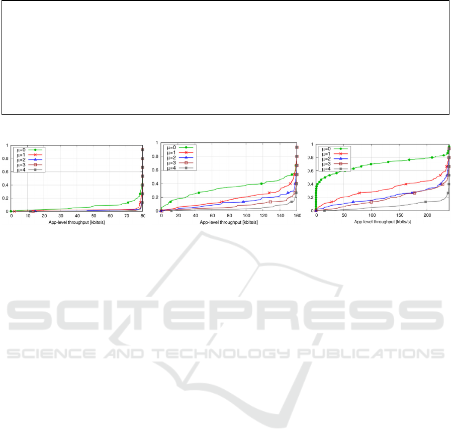
Figure 24: Snippet of the INI configuration file.
Figure 25: CDF of application-level throughput with different numerologies and increasing data rate.
the central site, i.e. served by the three central gNBs.
We run ten seconds of simulation on an Intel Core(TM)
i7 CPU at 3.60 GHz, with 16 GB of RAM, a Linux
Kubuntu 16.04 operating system, and OMNeT++ ver-
sion 5.3. Execution times are measured using the date
Unix command to obtain the time at the beginning and
at the end of the simulation, and computing the differ-
ence between the two values. The simulations are run
in batch, after disabling the graphical user interface.
Charts show the average values obtained from ten in-
dependent repetitions.
In order to assess the impact of CA, we consider
three CCs, whose carrier frequency is 700MHz, 2GHz
and 6GHz, respectively. Each CC has 10MHz band-
width, resulting in 50 RBs. Figure 22 shows the execu-
tion time when one, two and three CCs are simultane-
ously active in the systems. UEs are assigned to one of
the available CCs uniformly, hence traffic load is
equally distributed among the CCs. The execution time
depends linearly on the number of UEs. Fixing the
number of UEs and increasing the number of CCs has
little impact on the execution time, despite the fact that
it entails running the scheduler more often on each TTI.
On the other hand, increasing the number of UEs af-
fects the number of operations required for CQI report-
ing and interference computation.
Figure 23 shows the execution times when differ-
ent numerologies are employed. In this scenario only
one CC is employed, i.e. the one at 700 MHz. As ex-
pected, the time increases with the index 𝜇. This is be-
cause a larger 𝜇 implies a shorter TTI, hence both the
gNBs and the UEs need to perform all their operations
more frequently in the same simulated time.
5.2 Evaluating Different Numerologies
As described in Section 3, Simu5G allows one to assess
the performance of different network configurations.
In this section, we show how to configure some of the
main simulation parameters and build a simple sce-
nario for assessing the impact of different numerolo-
gies on the application-layer throughput at the UEs.
Using the scenario in Figure 12 as a basis, we as-
sume an FDD deployment with DL traffic only, where
30 UEs receive a CBR traffic. We assume all the gNBs
and UEs use one CC, whose bandwidth is 1.4MHz (six
RBs). We selected such a small bandwidth so that the
network saturates with a smaller number of UEs and
the effects on their throughput are more evident. Figure
24 shows a snippet of the INI file, where we configure
the parameters for CA and numerologies. First, the car-
rierAggregation module is configured with one CC by
setting the numComponentCarriers parameter to 1.
Then, the element of the componentCarrier vector
with index 0 (i.e., the only element in this configura-
tion) is configured with a carrier frequency of 700MHz
and six RBs. The numerologyIndex parameter, instead,
gets multiple values, represented by the iteration vari-
able ${numerology}, which ranges from 0 to 4. Using
this syntax, the OMNeT++ environment allows us to
automatically run one independent simulation run for
each value of the iteration variable. Then, we configure
the number of CCs used by gNBs and UEs, by setting
their numCarriers parameter to 1. Finally, the channel-
Model module is associated to CC with index 0, by set-
ting the componentCarrierIndex
parameter.
1. # configure the Carrier Aggregation modules
2. *.carrierAggregation.numComponentCarriers = 1
3. *.carrierAggregation.componentCarrier[0].carrierFrequency = 700MHz
4. *.carrierAggregation.componentCarrier[0].numBands = 6
5. *.carrierAggregation.componentCarrier[0].numerologyIndex = ${num=0,1,2,3,4}
6. # associate the CC to the channel models in the gNBs and the UEs
7. *.gNodeB*.lteNic.numCarriers = 1
8. *.ue[*].lteNic.numCarriers = 1
9. *.gNodeB*.lteNic.channelModel[0].componentCarrierIndex = 0
10. *.ue[*].lteNic.nrChannelModel[0].componentCarrierIndex = 0
SIMULTECH 2020 - 10th International Conference on Simulation and Modeling Methodologies, Technologies and Applications
78
We simulate the above scenario with increasing
sending rate, ranging from 80 to 240 kbps. Figure 25
shows the resulting CDFs of the application-level
throughput. As expected, we observe that when the
traffic load increases and the network approaches satu-
ration, the load of some UEs cannot be completely sat-
isfied and the percentage of UEs that are not able to get
their offered load is larger for lower numerology in-
dexes 𝜇 (i.e., larger subcarrier spacings).
5.3 Evaluating a MEC Scenario
In this section we describe a proof-of-concept scenario
involving migration of MEC applications running on a
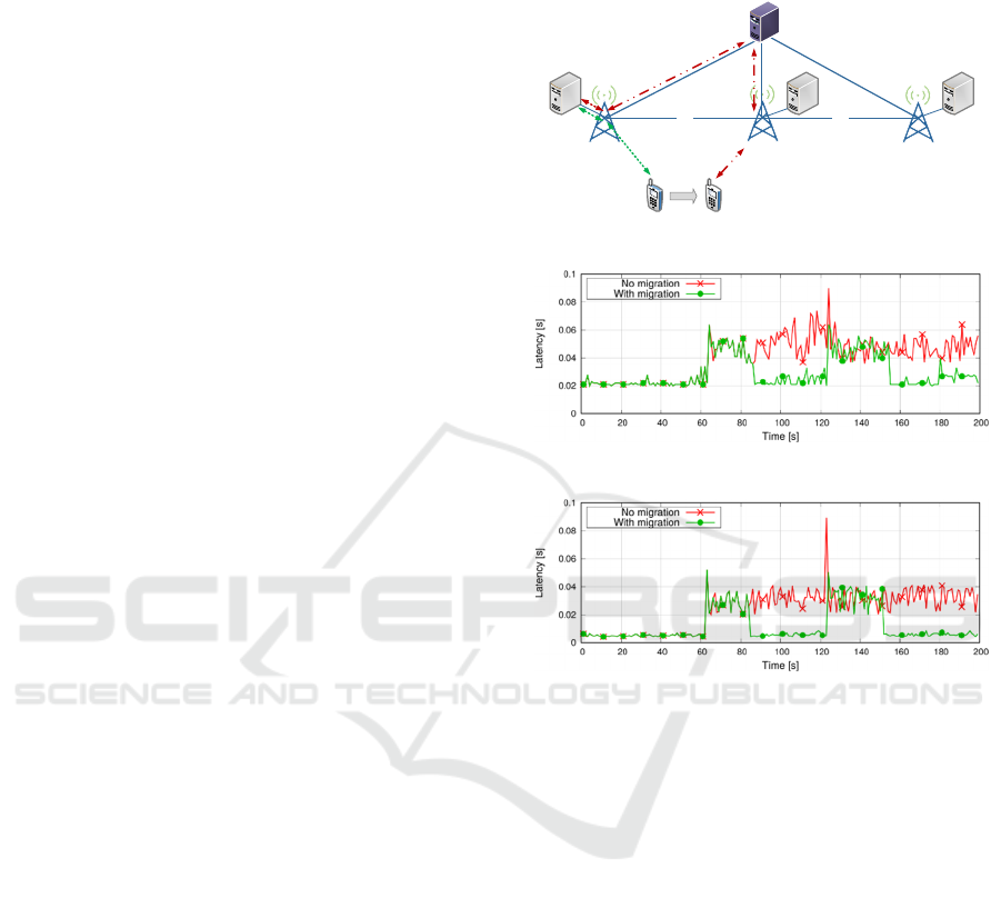
5G network. We consider the scenario of Figure 26,
where three servers representing Mobile Edge (ME)
hosts are respectively co-located with three gNBs. One
UE is linearly moving from the service area of gNB1
to that of gNB2 and gNB3, at a constant speed of 30
km/h. The UE offload tasks to the ME host periodi-
cally, with period 𝑇 200 ms. For each offloaded
task, the UE transfer the context to an ME application
running within the ME host, which performs computa-
tions and sends the context back to the UE. We let
𝑙
~𝑈
8,12
be the context size for task 𝑖 (hence, the
size of the 𝑖-th packet to be transmitted), measured in
kbits. Moreover, we model the processing time at the
ME host as 𝑇
𝑙
𝛽
𝐹
⁄
, where 𝛽
~𝑈
100,300
are the cycles per bit necessary for processing task 𝑖
and 𝐹9 Gcycles/s is the processing capacity at the
ME hosts (Emara et al., 2018).
We assume that at the beginning of the simulation
the UE offloads its tasks to ME host 1. When the UE
performs the handover to ME host 2 and 3, we consider
the two following scenarios: a) the UE keeps offload-
ing its tasks to ME host 1, and b) the UE offloads its
tasks to the ME host co-located with the serving gNB,
i.e. the ME service migrates according to the UE mo-
bility. In the first scenario, data needs to be routed
through the PGW, hence the additional latency is uni-
formly distributed between 15 and 35 ms (Emara et al.,
2018). In the second scenario, we assume that the mi-
gration needs a time in the range 20𝑠, 30𝑠, which is
compatible with the results in (Taleb et al., 2019).
More advanced migration algorithms and models can
be easily implemented and tested within Simu5G.
Figure 27 shows the latency required for obtaining
the result of the task offloading over time. The UE per-
forms the handover at 64s and 124s, where the latency
increases due to need of rerouting the traffic through
the PGW. Without service migration, the latency al-
ways stays above 35ms. When the application mi-
grates, the latency goes back to about 20ms after the
transient. Figure 28 shows the same metric when µ
3 is employed. As expected, the latency has the same
evolution, except for scaled-down values due to shorter
TTIs at the MAC layer.
gNB1
X2
UE
MecHost1
PGW/SGW
gNB2
gNB3
X2
MecHost2
MecHost3
Figure 26: Simulation scenario with ME app migration.
Figure 27: Latency of task offloading, µ=0.
Figure 28: Latency of task offloading, µ=3.
6 CONCLUSIONS
This paper presented Simu5G, a new simulation library
for 5G NR based on OMNeT++. To the best of our
knowledge, this is one of only two libraries allowing
end-to-end application-level communications in com-
plex, heterogeneous scenario, thanks to its modular and
INET-compatible modelling, and the only one model-
ling coexistence of 4G and 5G access in ENDC deploy-
ments. We have described Simu5G’s resource man-
agement and protocol layers, and we have presented
results which are representative of its capabilities and
execution cost. Future work, well under way at the time
of writing, involves evaluating the performance and ca-
pabilities of Simu5G running as a network emulator
with real applications.
Simu5G: A System-level Simulator for 5G Networks
79

REFERENCES
Mehlfuerer, C., Wrulich, M., Ikuno, J.C., Bosanska D., Rupp,
M., Simulating the long term evolution physical layer, in
Proc. 17th EUSIPCO, Glasgow, UK, 2009.
Patriciello, N., Lagen, S., Bojovic, B., Giupponi, L., An E2E
Simulator for 5G NR Networks. In Elsevier SIMPAT,
vol. 96, 101933, November 2019.
Baldo, N., Miozzo, M., Requena, M., Nin Guerrero, J.,. An
Open Source Product-Oriented LTE Network Simulator
based on ns-3. in Proc. MSWIM 2011, Miami Beach, FL,
USA, November 2011.
Jao, C. et al., WiSE: A System-Level Simulator for 5G Mo-
bile Networks. in IEEE Wireless Communications, vol.
25, no. 2, pp. 4-7, April 2018.
Müller, M., et al., Flexible multi-node simulation of cellular
mobile communications: the Vienna 5G System Level
Simulator. In J Wireless Com Network , 227, 2018.
Virdis, A., Stea, G., Nardini, G., SimuLTE: A Modular Sys-
tem-level Simulator for LTE/LTE-A Networks based on
OMNeT++. In SIMULTECH 2014, Vienna, AT, August
28-30, 2014.
Virdis, A., Stea, G., Nardini, G., Simulating LTE/LTE-Ad-
vanced Networks with SimuLTE. In Obaidat, M.S.,
Kacprzyk, J., Ören, T., Filipe, J., (eds.) Simulation and
Modeling Methodologies, Technologies and Applica-
tions, Springer, 2016.
Virdis, A., Nardini, G., Stea, G., Cellular-networks simula-
tion using SimuLTE. In A. Virdis, M. Kirsche, (eds.) Re-
cent Advances in Network Simulation, Springer, Cham,
pp. 183-214, May 2019.
Nardini, G., Virdis, A., Stea, G., Buono, A., SimuLTE-MEC:
extending SimuLTE for Multi-access Edge Computing.
OMNeT++ Comm. Summit 2018, Pisa, IT, 5-7 Sep. 2018
3GPP - TR 38.801, Study on new radio access technology:
Radio access architecture and interfaces (Release 14).
March 2017.
3GPP - TR 37.340 v16.0.0, Evolved Universal Terrestrial
Radio Access (E-UTRA) and NR; Multi-connectivity;
Stage 2 (Release 16). December 2019.
Shen, Z., Papasakellariou, A., Montojo, J., Gerstenberger, D.,
Xu, F., Overview of 3GPP LTE-Advanced Carrier Ag-
gregation for 4G Wireless Communications. IEEE Com-
munications Magazine, February 2012.
3GPP TR 38.211 v16.0.0, NR; Physical channels and modu-
lations (Release 16). December 2019.
3GPP TR 38.213 v16.0.0, NR; NR; Physical layer procedures
for control (Release 16). January 2020.
3GPP TR 38.214 v16.0.0, NR; Physical layer procedures for
data (Release 16). January 2020.
3GPP TR 38.300, NR; NR and NG-RAN Overall Descrip-
tion; Stage 2 (Release 16). December 2019.
3GPP TR 36.873 v12.7.0, Study on 3D channel model for
LTE (Release 12). December 2017.
3GPP - RP-180524, Summary of calibration results for IMT-
2020 self evaluation. TSG RAN Meeting #19, Chennai,
India, 19-22 March 2018.
Emara, M., Filippou, M.C., Sabella, D., MEC-Assisted End-
to-End Latency Evaluations for C-V2X Communica-
tions. in Proc. EuCNC 2018, Ljubljana, Slovenia, 2018.
Taleb, T., Ksentini A., Frangoudis, P.A., Follow-Me Cloud:
When Cloud Services Follow Mobile Users. in IEEE
Trans. on Cloud Computing, vol. 7, no. 2, pp. 369-382,
April-June 2019.
SIMULTECH 2020 - 10th International Conference on Simulation and Modeling Methodologies, Technologies and Applications
80
