
Design and Preliminary Evaluation of a Dextrous Encounter Type
Force Feedback Interface
Anthony Chabrier
1,2
, Florian Gosselin
1a
and Wael Bachta
2b
1
CEA, LIST, Interactive Robotics Laboratory, F-91120 Palaiseau, France
2
Sorbonne Université, CNRS, UMR 7222 and INSERM, UI 1150,
Institut des Systèmes Intelligents et de Robotique, F-75005, Paris, France
Keywords: Force Feedback Interface, Encounter Type, Dexterous.
Abstract: Force feedback interfaces aim at allowing natural interactions with a virtual or distant environment with a
physical sense of presence. Commercially available systems suffer however two limitations. First, most of
them are equipped with a handle whose geometry constraints the movements that can be efficiently simulated
to the manipulation of tools shaped like the handgrip. Second, the handle is always grasped in hand and the
user feels the friction and inertia of the system even in free space, hence a limited transparency. Dexterous
interfaces were introduced to cope with the first issue, while encounter type devices, which are detached from
the user’s hand and contact it only when haptic feedback is required, allow to tackle the second limitation. To
date however, no device efficiently integrates both principles. The aim of this paper is to introduce a new
device intended to do so, i.e. to be both dexterous, allowing to simulate any grasp type (limited to two fingers
in a first step), and of encounter-type, hence an improved transparency. Its design is presented in details, and
first experimental results showing the ability of the device to follow user’s movements are introduced.
1 INTRODUCTION
Haptic interfaces allow natural gesture interactions
with virtual or remote environments. Therefore, they
track the user’s movements and provide force
feedback generated e.g. when contacts occur between
the user’s avatar and virtual objects, thus improving
the operator’s immersion by reproducing a physical
sense of presence in the virtual or distant world.
To date, however, commercially available haptic
interfaces suffer limitations. Indeed, despite
continuous efforts to develop and propose more
versatile devices, most of them are still manipulated
via a handle fixed at the end of a serial or parallel arm
structure (Massie and Salisbury, 1994) (Perret et al.,
2013). This simple solution is well suited when
simulating an operation performed with a given tool.
However, they limit the user’s dexterity and are less
adapted when manual manipulation is required or
when several tools with different shapes are used
successively. In this case, a dexterous interface is
required.
a
https://orcid.org/0000-0003-3412-8144
b
https://orcid.org/0000-0002-8120-1124
Designing a dexterous haptic interface is however
an extremely difficult task due to the complexity of
the hand kinematics, inter-individual variability, and
great sensitivity of the human hand (see for example
recent reviews of dexterous haptic interfaces in (Heo
et al., 2012) and (Perret and Vander Poorten, 2018)).
To tackle this issue, researchers often propose a
simplified design allowing the measurement of all
hand’s movements but providing force feedback in
only some directions, usually opposite to the fingers’
flexion. Despite lighter and more compact, such
designs can only resist hand closure and do not allow
simulating the forces occurring when touching the
virtual objects in any arbitrary direction. Therefore,
miniature robots with several degrees of freedom
(DoFs) allowing multi-directional force feedback are
needed for each finger. This solution theoretically
allows the rendering of any force on the fingers.
However, their structure is in turn complex,
cumbersome and heavy. Also, their transparency is
often limited, as small motors with multistage
reducers are required to keep volume and weight
420
Chabrier, A., Gosselin, F. and Bachta, W.
Design and Preliminary Evaluation of a Dextrous Encounter Type Force Feedback Interface.
DOI: 10.5220/0009824804200429
In Proceedings of the 17th International Conference on Informatics in Control, Automation and Robotics (ICINCO 2020), pages 420-429
ISBN: 978-989-758-442-8
Copyright
c
2020 by SCITEPRESS – Science and Technology Publications, Lda. All rights reserved

reasonable. This affects the user’s ability to make
abstraction of the interface and prevents natural
gestures. Preserving a high transparency and in
particular a high haptic sensitivity is however of
particular importance for fine manipulation, i.e. when
grasping and precisely manipulating small objects.
To overcome this limitation, researchers proposed
to implement intermittent contacts (Mc Neely, 1993)
(Yoshikawa and Nagura 1997), i.e. the user is no
more in contact with the device in free space. The
device remotely follows his movements and comes
into contact with the hand only when he touches a
virtual object. This way, a perfect transparency is
achieved in free space. Furthermore, the transition
between free space and contact is also more natural as
it is rendered via a physical contact with the robot in
the real world. This greater sensitivity is particularly
interesting during fine manipulation tasks.
It is worth noting however that, to date, none of
the two alternative solutions existing for the
implementation of the intermittent contact paradigm,
i.e. encounter and encountered-type interfaces, allows
simulating dexterous interactions in a perfect way:
On the one hand, the underlying principle of
encountered-type haptic interfaces is to use a
robot whose end effector moves on the surface of
the closest to the user virtual object and waits for
him to come into contact with it, the robot being
often static in this phase. This end effector has
usually a shape similar to the simulated objects,
or it is composed of several basic geometric
primitives (e.g. planes, corners, edges,…). As a
result, it can only simulate objects having this
given shape, which was initially most of the time
fixed (Tachi et al., 1994) (Yokokohji et al.,
1995), even if some more recent devices propose
reconfigurable end-effectors (Yokokohji et al.,
2005) (De Araujo et al., 2010). Even so, the
simulation is limited to given classes of objects
and the device cannot really be called dexterous.
On the other hand, encounter-type devices
usually carry a hollow shaped end-effector that
surrounds the user’s finger and closely tracks it
without colliding with it in free space. When the
user moves towards the environment, the
interface slows down so that the end-effector
enters in contact with the finger at the exact
position and time the avatar collides with the
virtual environment. Such devices theoretically
allow a greater freedom than encountered-type
interfaces in terms of the variety of objects that
can be simulated. However, most of them allow
interacting with only one finger (Hirota and
Hirose, 1993) (Yoshikawa and Nagura 1997,
1999) (Gonzalez et al., 2015a). Only few
encounter-type interfaces with several fingers
exist (Nakagawara et al., 2005) (Fang at al.,
2009), but they are not as transparent in free
space as mono-finger’s ones as they make use of
optical IR tracking systems with reflective plates
resting on fingers to measure their movements.
Also, they are unfortunately not really dexterous.
Indeed, their joints are coupled, thus limiting the
fingers’ movements to some given synergies.
Moreover, force feedback is limited to flexion-
extension. They can thus simulate the resistance
of an object grasped in hand, but they do not
allow simulating forces occurring in any
arbitrary direction (e.g. external forces exerted
on this object, or friction associated with
tangential movements along a surface).
In this paper, we present the design and
preliminary evaluation of a device that is intended to
tackle the above-mentioned limitations. It is:
More dexterous than existing intermittent contact
devices, i.e. it can track and apply forces on
several fingertips in any direction, allowing to
simulate different grasp types.
More transparent than existing dexterous
interfaces thanks to its truly intermittent-contact
nature, i.e. it is not at all in contact with the
fingertips in free space.
The main innovation of this device is the
combination of intermittent contacts and dexterity,
each capacity being derived from the best practices.
Regarding intermittent contacts, it relies on the
encounter type paradigm which was shown above to
be the most promising solution for the
implementation of a dexterous haptic interface.
Regarding dexterity, it is based on the use of small 6
DoF robots with 3 DoF force feedback on each finger
(limited to two fingers in a first step).
2 DESIGN AND
IMPLEMENTATION
2.1 Specifications
The following criteria were considered for the
specification of our interface:
1/ Fine dexterous manipulation: our aim is to
develop a device allowing the simulation of fine
dexterous manipulation. Therefore several grasp
types are required to adapt to the manipulated tools
and objects (Feix et al., 2009). This calls for a
dexterous device allowing natural interactions with
Design and Preliminary Evaluation of a Dextrous Encounter Type Force Feedback Interface
421
the palm and fingers. Also, the links and joints have
to be positioned and dimensioned so that the robot
does not limit the fingers’ movements.
2/ Universal fit: two types of dexterous interfaces
can be found in the literature. Exoskeletons have links
and joints similar to the hand, and they are attached
to every phalanges on which they can independently
apply forces. They allow simulating both precision
and power grasps, at the price however of strong
mechanical constraints as their joints have to be
roughly aligned with the fingers’ ones. Hence, they
must be tuned to each user, which is not convenient
for a universal device that can be used by different
operators. On the contrary, fingertip interfaces are
fixed only on the palm and distal phalanges. Despite
being restricted to the simulation of precision grasps,
they can more easily fit different users and their
design is much simpler. Our application being mainly
focused on precise manipulation, we decided to
develop a fingertip haptic interface for the thumb and
index fingertips as in (Gosselin et al., 2005) and
(Frisoli et al. 2007). This is sufficient for the
manipulation of small objects.
3/ High transparency and force feedback quality:
haptic interfaces should be transparent in free space,
i.e. display a mechanical impedance that is
sufficiently low for the user to forget their presence.
They should also be able to provide high impedances
to simulate realistic contacts with stiff surfaces. This
contradiction usually leads to a compromise between
a high transparency in free space (i.e. low friction and
inertia) and realistic force feedback in contact (i.e.
high forces and stiffness). To overcome this
limitation, we will implement intermittent contacts. It
is worth noting that a single finger can apply almost
only forces on objects, torques being generated by a
combined use of several fingers. Consequently, only
3D force feedback is required at the fingertips.
4/ Fatigueless use: glove-type interfaces, even
optimized, often remain relatively heavy and lifting
the device is quickly tiring if it is worn on the hand or
arm. To cope with this problem, we will mount the
device on a passive counterbalancing system.
2.2 Electro-Mechanical Design
2.2.1 Overview of the System
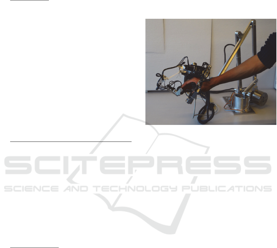
The two fingers encounter-type dexterous haptic
interface developed to answer the above-mentioned
specifications is illustrated in Figure 1. It is composed
of two robots equipped with intermittent contact
hollow-shaped end-effectors facing the thumb and
index fingertips and a basis grasped with the
remaining fingers (this is an interim solution until the
development of an encounter type palm tracking
system). The whole interface is mounted on a passive
counterbalancing system and it is linked with an
external controller. Each of these components will be
presented in details below.
Figure 1: Encounter-type dexterous haptic interface
prototype.
2.2.2 Fingers’ Robots
The index finger has four DoF, the thumb five. One
could think that robots with the same movement
capabilities are sufficient to follow the movements of
these fingers. This requires however that at least some
of the robots’ joints are aligned with the fingers’ ones.
This cannot be guaranteed here as the glove will be
used by different users having various hand sizes and
morphologies. It is also worth noting that we intend
to use an encounter type solution for the palm in the
future. In this case, the device will no more be fixed
on the hand and the position of the robots relative to
the palm will vary during operation. In these
conditions, the robots must have 6 DoF to be able to
follow any fingers’ movements.
In practice, such 6 DoF structures are usually
obtained with separate positioning and orientation
stages allowing to displace the end-effector, resp. to
orient it. This efficient solution, illustrated in Figure
2 for the index finger, will be used here.
As already mentioned in section 2.1, it is worth
noting that a single finger can apply almost only
forces on the environment, torques being generated
by a combined use of several fingers. Only 3D force
feedback is thus required at the fingertips. Still, the
robots should accommodate the distal phalanx’
changes in orientation occurring during hand closure.
ICINCO 2020 - 17th International Conference on Informatics in Control, Automation and Robotics
422
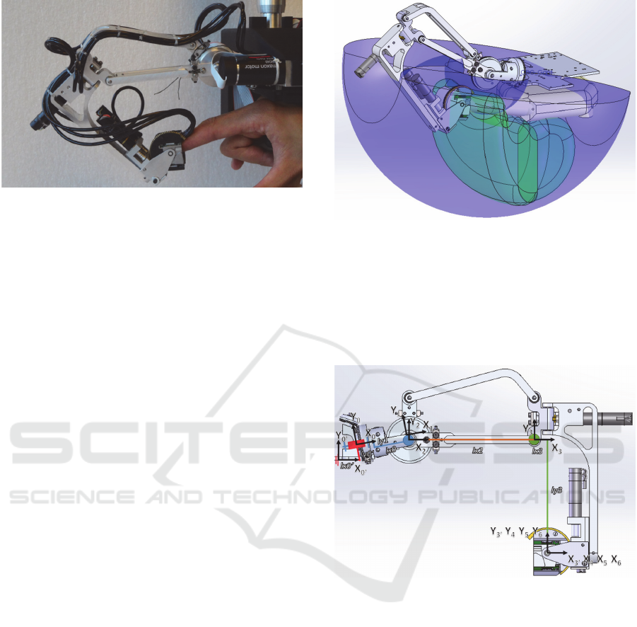
Figure 2: Index finger’s robot architecture.
In classical force feedback gloves, the rotation
joints are passive. However, due to the intermittent
nature of our device, the robot’s end effector will be
detached from the fingertip in free space. As a
consequence, it will not follow the fingertip passively
and the end effector has to be actively oriented.
2.2.3 Kinematics
The positioning stage of our device is composed of a
pivot joint and a parallelogram as in (Massie and
Salisbury, 1994), and the actuators are fixed on the
palm in order to reduce the robot’s moving parts
inertia, their movements being transmitted to the
joints using cables. The pivot joint is tilted and shifted
upwards as proposed in (Gosselin at al., 2005) to
ensure that the fingertip will never cross this axis,
which would lead to a singular configuration.
The links’ dimensions were optimized in CAD so
that the devices’ workspace encompasses the range of
motion of the fingers, expanded to take into account
the encounter-type related clearance between the
fingers and the end-effector (plus a clearance between
the palm and the basis as the later will also be of
encounter-type in the future). We made here the
assumption that the total clearance will remain below
15mm (3mm for the fingertips plus 12mm for the
palm, these values being computed taking into
account the user’s and robot dynamics using the
methodology proposed in (Gonzalez et al., 2015b)).
With these assumptions, we iteratively dimensioned
the links, with additional constraints on the absence
of collisions with the fingers and on the integration of
the end-effector and orientation stage actuators.
Optimal dimensions are: 10° tilt angle relative to the
horizontal for the index (0° for the thumb), length of
the first, second and third links respectively equal to
40mm, 95mm and 86mm. With these dimensions, the
robots can span the index finger and thumb’s
workspaces inflated by 15mm (see Figure 3 for the
index, similar results were obtained for the thumb).
Figure 3: Inflated index finger’s (in green) and robot’s (in
blue) workspace.
The orientation stage is composed of three pivot
joints with intersecting axes, whose range of motion
were iteratively adjusted so as to accommodate the
index and thumb reorientations occurring during
hand’s movements.
Figure 4: Index finger’s kinematics.
With the notations given in Figure 4, the
geometric model of the robot can be written as:
T
0’0
=trans(X
0’
,l
x0’
).trans(Y
0’
,l
y0’
).rot(Z
0’
,q
z0’
) (1)
T
01
=trans(X
0
,l
x0
). rot(X
1
,q
1
) (2)
T
12
=trans(Y
1
,-l
y1
).rot(Z
2
,q
2
-q
z0’
) (3)
T
23
=trans(X
2
,l
x2
).rot(Z
3
,q
3
) (4)
T
33’
=trans(X
3
,l
x3
).trans(Y
3
,-l
y3
) (5)
T
3’4
=rot(Y
3’
,q
4
).rot(Z
4
,q
z4
) (6)
T
45
=rot(X
4
,q
5
) (7)
T
56
= rot(Z
5
,q
6
) (8)
With q
z4
an additional parameter introduced for
the thumb’s robot whose forearm is slightly tilted
Design and Preliminary Evaluation of a Dextrous Encounter Type Force Feedback Interface
423
compared to the index’ one in order to avoid
collisions with the thumb (q
z4
=0 for the index).
2.2.4 Actuation
To select the actuators of the positioning stage (which
acts as an encounter type haptic interface), both free
space and contact modes must be considered:
In contact mode, the robot should be able to
sustain the fingers’ forces, typically in the range
between 5N continuous and 15N during few
seconds (Gonzalez et al., 2014). To compute the
associated motor torques, we use force
dimensioning ellipsoids as explained in
(Gosselin, 2016). Another constraint in contact
mode is to have a robot that is sufficiently stiff to
allow for the simulation of hard surfaces.
Theoretically, a stiffness above 24N/mm is
required to simulate a rigid surface without visual
feedback (Tan at al., 1994). It is however
possible to rely on the vision predominance over
haptics to give the illusion of stiffness with a
much lower rigidity when vision is available.
Here, we set our requirement at 10N/mm.
Regarding free space, the robot should have a
sufficient acceleration capacity to follow the
user’s movements without colliding with his or
her fingers.
The actuators selected after an iterative optimization
taking into account the above-mentioned criteria but
also transparency and integration constraints are
Maxon DC motors (ref. RE25 339152, 20W, 24V,
115g, max. torque 30.4mN.m continuous, 325mN.m
peak) equipped with 256ppt encoders, associated with
a cable capstan reducer to keep the system highly
backdriveable. In order to limit the size of the
reduction stage, we used two stages reducers and
made use of miniature Dyneema cables which can
bend narrower than steel cables (ref. Berkley
Whiplash 1077221, 0.28mm, 44.9kg resistance). The
first stage has a reduction ratio of 4:1 and the second
stage a ratio of 6:1 on the abduction-adduction axis
(hence an output torque of 730mN.m) and 7:1 on the
other axes (output torque 851mN.m).
Regarding orientations, there is no need for
backdriveability. The only requirement is it follow the
fingers’ change in orientation at a sufficient speed.
Here, to allow for a simple and compact design, we
used small and light actuators which are integrated
directly in the orientation stage, and worm and wheel
gears to both actuate the end-effector and sustain the
force applied by the user once in contact. Such systems
are highly compact, yet they are not backdriveable and
naturally resist external forces. After a careful review
of the components available, we selected miniature
Maxon DC motors (réf. RE10 256105, 1.5W, 12V,
10g, max. torque 1.55mN.m continuous, 3.24mN.m
peak) equipped with 10ppt encoders. They are
associated with 16:1 planetary gearheads (ref. GP10A
218416) and HO58 worm and 25 teeth HO59/7 wheels
on the two first axes and with a 4:1 planetary gearhead
(ref. GP10A 218415) and a HO58 worm and a 75 teeth
HO59/11 wheel on the last axis.
2.2.5 Hollow Shaped End-effector
In an encounter type device, the end effector serves
as a contact surface only when force feedback is
required. In free space, it must follow the finger
remotely without entering in contact with it.
Therefore, a sufficient clearance must be provided to
allow the robot accelerating and catching up the
finger when the later moves. This clearance depends
on the fingertip and robot’s dynamics. To design the
end-effector, we used the same hypotheses as in
(Gonzalez et al., 2015b), i.e. maximum finger speed
and acceleration of 1.26m/s and 24.5m/s² in flexion-
extension and 0.26m/s and 4m/s² in abduction-
adduction and robot dynamics similar to those of the
first axis of the PHANToM Premium 1.5 High Force.
In these conditions, the tracking errors remain below
3.1mm in flexion-extension and 0.6mm in abduction-
adduction. Taking the fingers dimensions into
account, we arrive at a cylinder with a diameter of
24mm for the index and 28mm for the thumb. The
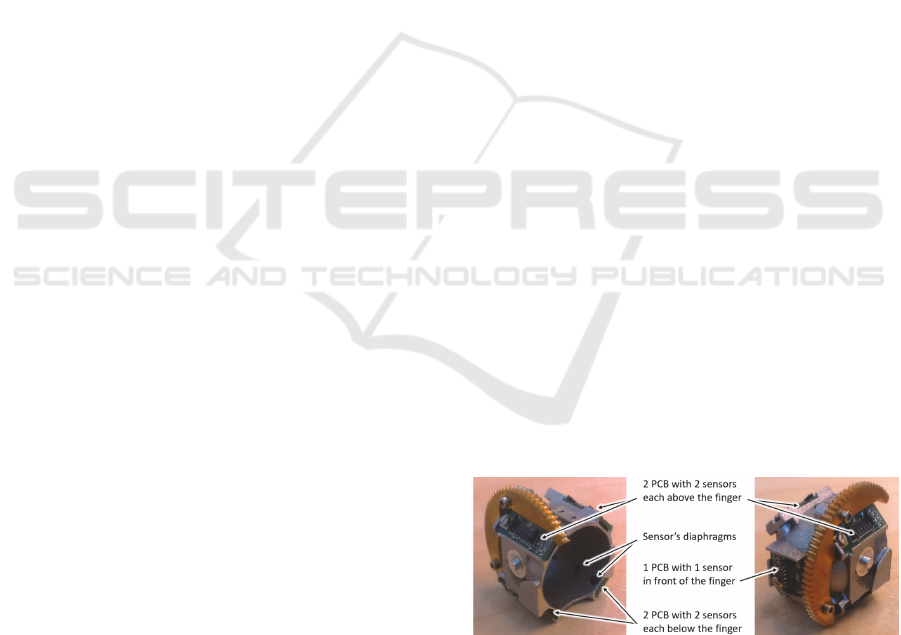
configuration of the finger inside the end-effector is
measured with nine infrared proximity sensors (ref.
Vishay VCNL4010). As shown in Figure 5, eight of
them are placed around the distal phalanx in two
different planes, the last one being in front of the
fingertip. It is worth noting that no sensor is placed in
front of the finger pulp, allowing to minimize the
thickness of the end-effector below the finger.
Figure 5: Placement of the proximity sensors in the end-
effector.
The ability of this end-effector to measure the
position and orientation of the finger was carefully
checked. It is capable of measuring the movements of
a fingertip in the ranges of 1-10mm in all directions,
±10° in abduction/adduction and ±20° in flexion/
ICINCO 2020 - 17th International Conference on Informatics in Control, Automation and Robotics
424
extension, with errors about 0.2mm and 0.4° near the
center of the end-effector (Chabrier et al., 2017).
2.2.6 Fixed Basis
For an optimal transparency of the system, intermittent
contacts should also be implemented on the palm, so
that the robot doesn’t touch the hand at all in free space.
In a first step however, for the sake of simplicity, we
decided to equip the basis on which the index and
thumb robots are fixed with a handle grasped with the
remaining fingers. Their position and orientation on the
basis are optimized in CAD so that they can follow the
fingers’ movements over their workspace.
2.2.7 Counterbalancing System
A passive counterbalancing system is used to
compensate for the weight of the device which is too
heavy to be worn on the hand. In practice, we
advantageously make use of a pantograph architecture
(ratio 3:1) equipped with a counterweight (mass
7.43kg, see Figure 1). This solution allows to keep the
distance ratio between the interface’s centre of mass,
the axes of the pantograph and the counterweight
unchanged. This way, the weight of the glove is
compensated in any position in the workspace of the
supporting arm. This system is further equipped with
15-bits angular encoders (ref. Gurley A19), allowing
for the measurement of the hand position in space with
a minimum resolution of 0.14mm. A passive
orientation system is added to allow for the glove to
move freely in orientation. Its axes intersect at the
centre of mass of the glove (fingers extended) so that
no torque is generated on the hand. 12 bits angular
encoders are used on these axes (ref. CUI AMT11),
hence a resolution of 0.09° on the hand orientation.
2.2.8 Electronics
Our interface integrates 18 encoders (6 on each robot
of the glove plus 6 in the supporting arm), 18 infrared
sensors (9 in each end-effector) and 12 actuators. The
electronics monitoring the data from all these sensors
and controlling the motors should work at a frequency
that is sufficient for a stable and performant control of
the device, typically in the order of 1 kHz. To reach this
requirement, we use components linked with an
EtherCAT bus. For the measurement of the fingertip’s
position in the end-effector, a custom designed card
based on a FPGA was developed. It allows measuring
the 18 signals of the proximity sensors in parallel at a
framerate higher than 1kHz. For the measurement of
the supporting arm’s encoders, we use Beckhoff
EL5002 units connected to the Gurley A19 sensors via
a SSI bus and Beckhoff EL5101 units connected to the
CUI AMT11 encoders. Finally, the motors and motors’
encoders are connected to 2 Technosoft 6 axes
iPOS360x SY-CAT cards each equipped with 3
iPOS3602 VX-CAN and 3 iPOS3604 VX-CAN servo-
drives (the former can deliver a maximum current of
3.5A that fits the RE25, the later a maximum current of
1A well adapted for the RE10). This solution allows all
data to be properly synchronized and transmitted to a
master controller by the same fieldbus.
3 CONTROLLER
3.1 Introduction
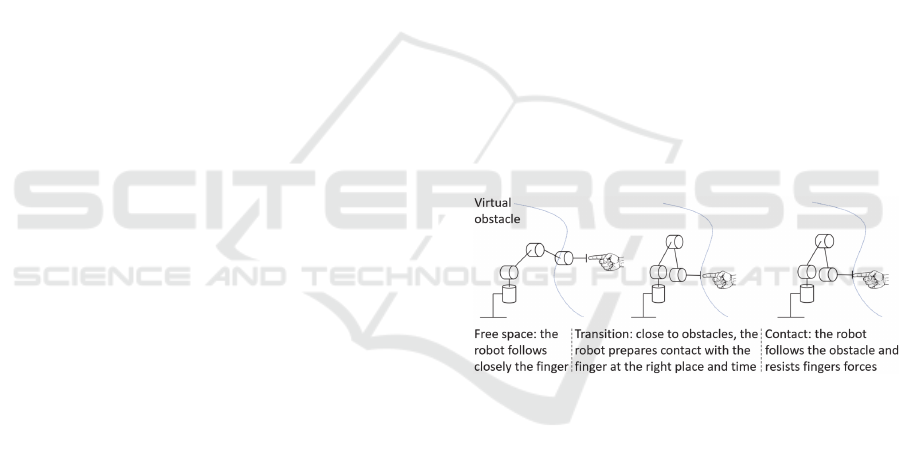
As shown in Figure 6, encounter type haptic
interfaces can be in three different states: 1- free
space, where the main goal is to follow the finger’s
movements at a close distance without entering in
contact with it, 2- contact, where force feedback
should be generated in a proper and stable way, and
3- transition, which should properly manage the
transition between previous modes so that the finger
encounters the end effector of the robot at the exact
place of the obstacle and the exact avatar contact time.
Figure 6: Encounter type interface principle of operation.
Impedance control is usually used to control such
devices, both in free space and contact modes.
However, the reference position is different in both
conditions, the goal being to keep the fingertip center
at the centre of the hollow end-effector in free space
while the fingertip pulp is in contact with the end-
effector’s inner surface in contact modes. (Gonzalez
et al., 2015a) has shown that abrupt transitions
between these modes produce instabilities and that
smooth transitions are preferable as they remain
stable (provided carefully adjusted gains).
The situation is slightly different here, as we have
to manage both the positioning stage which functions
as an encounter type device, and the orientation stage,
which is more simply controlled in speed in order to
follow the fingertip orientation. Details on the
controller are given below.
Design and Preliminary Evaluation of a Dextrous Encounter Type Force Feedback Interface
425
3.2 Positioning Stage
3.2.1 Control in Free Space
In free space, the end effector should remotely follow
the fingertip without any collision. We use therefore
an impedance control scheme intended to minimize
the Cartesian error 𝜀
/,
between the absolute
position 𝑋
/
of the centre of the end-effector and the
absolute position 𝑋
/
of the fingertip. In practice,
this control scheme is implemented at the joint level
to increase the robustness of the controller (Plumet et
al., 1995), the tracking torque 𝜏
being function of the
position error 𝜀
/,
computed in the joint space using
the robot’s Jacobian Matrix 𝐽𝑞. A proportional and
derivative controller with properly tuned gains is used
for stability reasons (see Figure 7).
Figure 7: Positioning stage control in free space.
3.2.2 Contact Mode
In contact mode, the fingertip is in contact with the
end-effector’s inner surface which is in charge of
force rendering. The user’s skin being then at the
same position as the end effector’s inner surface, the
penetration 𝜀
/,
of the fingertip in the virtual
obstacle (𝑣𝑜), that is the distance between the skin
(obtained as 𝑋
/
𝑅
with 𝑋
/
the position of the
fingertip’s centre and 𝑅
the fingertip radius) and the
obstacle 𝑋
/
, is equal to the distance between the
end-effector’s inner surface (obtained as 𝑋
/
𝑅
with 𝑋
/
the position of the end effector and 𝑅
its
radius) and the obstacle. Hence we have 𝜀
/,
𝑋
/
𝑅
𝑋
/
𝜀
/,
𝑋
/
𝑅
𝑋
/
.
The resulting interaction forces are calculated using a
modified Kelvin-Voigt model (Achhammer et al.,
2010) with the hypothesis that virtual obstacles are
modelled as viscoelastic elements without tangential
friction. With 𝜀
/,
the derivative of 𝜀
/,
, the
controller can be expressed as 𝑍
𝐾
𝐵
.s if
𝜀
/,
is negative, 𝑍
𝐾
if 𝜀
/,
is positive.
Figure 8: Positioning stage control in contact mode.
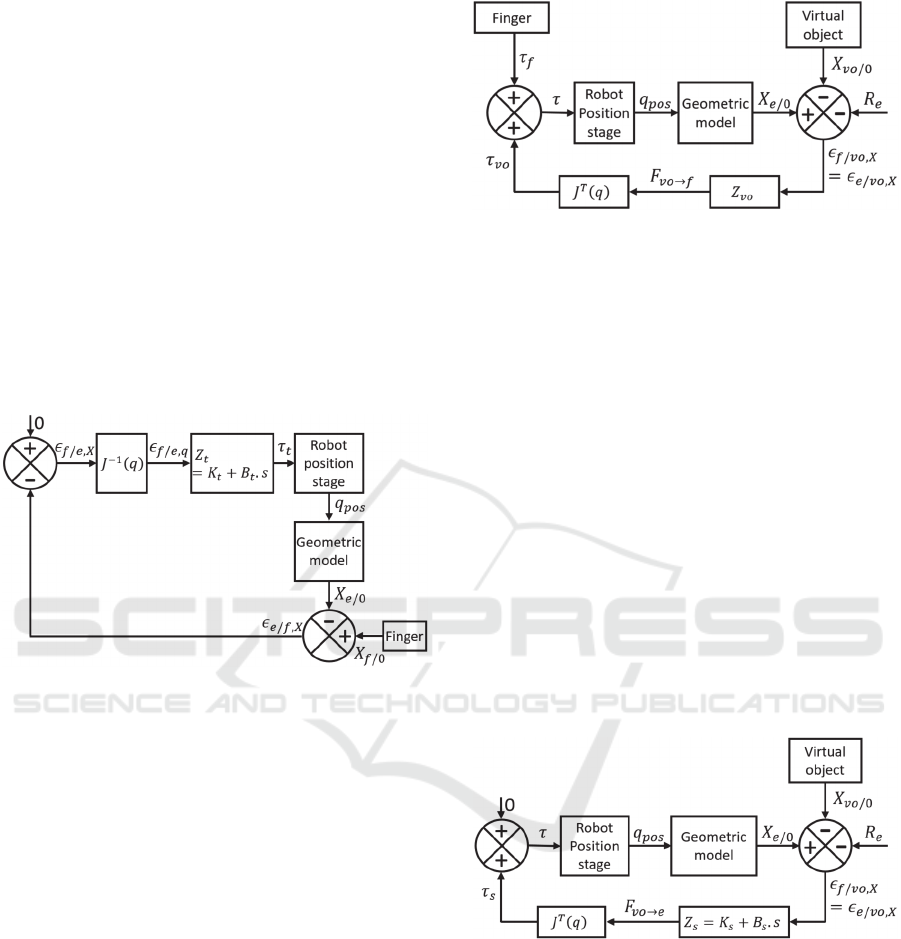
3.2.3 Transitions
Transitions have to be initiated as soon as the user’s
avatar is close enough to the virtual obstacles. Here,
we propose to take advantage of the fact that, in free
space, the inner surface of the end defector is always
in advance to the finger and will thus approach the
obstacles before the finger. In practice, we propose to
initiate the transition as soon as the end-effector’s
inner surface encounters the obstacle. The main goal
is then to ensure that the end-effector’s inner surface
remains positioned at the surface of the virtual
obstacle and to stabilize it before the finger contacts
it. As shown on Figure 9, this principle can be
implemented in a similar way as the contact mode.
However the goal is here to stabilize the ring as
quickly as possible, i.e. with the highest possible yet
stable gains 𝐾
and 𝐵
, while the gains in contact
mode are expected to simulate the objects behaviour
and can be lower.
Figure 9: Positioning stage control during stabilisation.
It should be noticed that, in practice, such
proposal still introduces a transition between the free
space and stabilization phases. In order to avoid
instabilities at that moment, we implement a smooth
transition that proves to be stable if the gains are
chosen adequately (Gonzalez et al., 2015a). Therefore
we introduce a function 𝛽𝑡 that varies linearly
between 0 and 1 and implement a combination of the
tracking torque 𝜏
and stabilisation torque 𝜏
for a
short time just before the transition mode (i.e. 𝜏
𝛽
𝑡
.𝜏
1𝛽
𝑡
. 𝜏
).
ICINCO 2020 - 17th International Conference on Informatics in Control, Automation and Robotics
426
A transition also occurs between the stabilization
phase and the contact mode. As the control scheme is
the same, except different gains, we simply manage
this transition through gains scaling, which are
initiated as soon as the end-effector’ speed is low
enough, meaning that it is already stabilized.
The global control scheme combining free space,
free space to stabilization transition, stabilization
phase, transition to contact and contact state is
illustrated in Figure 10.
Figure 10: Global control scheme in position.
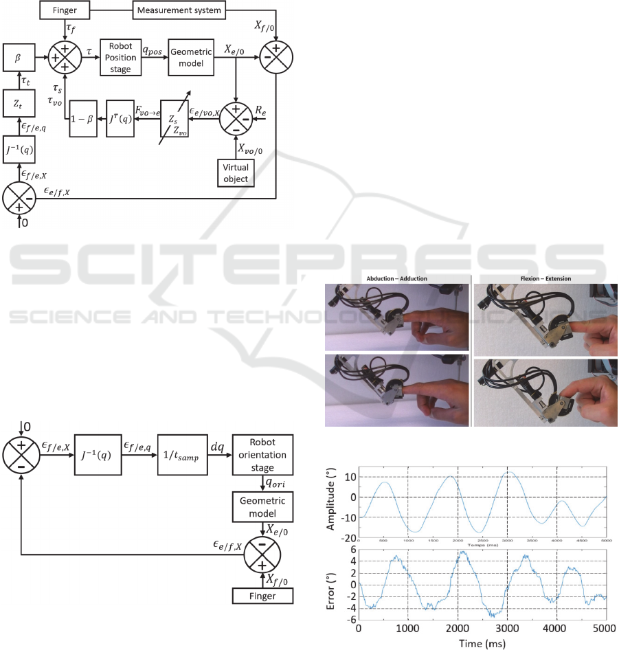
3.3 Orientation Stage
For the orientation stage, we use a simple joint speed
control based on the sampling time 𝑡
(speed
control is preferred over impedance control in this
case as the orientation stage’s encoders have a very
low resolution which limits the gains that can be
implemented in an impedance controller to unusable
values).
Figure 11: Orientation stage control.
It is worth noting that while several control modes
are required for the positioning stage, the controller
always remains the same for the orientation stage.
4 PRELIMINARY EVALUATION
The haptic interface presented in this paper as well as
its controller are still under development and we were
only able to test the index finger’s robot’s behaviour,
and only in free space and contact modes.
4.1 Free Space Finger Tracking
The first tests were intended to verify the ability of
the system to follow the index finger in free space.
The positioning stage being similar to previous
systems developed by the authors which have already
been demonstrated functioning well (Gonzalez et al.,
2015a), (De La Cruz Fierro et al., 2017), we focused
more specifically on the orientation stage. The
positioning stage was blocked in position and the
orientation stage was controlled in speed to follow the
finger’s movements. Figure 12 illustrates the
movements used during these tests. They correspond
to a range of motion of about 30° in abduction-
adduction and about 70° in flexion-extension (as the
position of the end-effector is fixed, the user has to
move his hand to rotate the end-effector). Figures 13
and 14 illustrate the results obtained (the amplitude of
the movement is measured by the orientation stage
and the error is measured by the end effector).
Figure 12: Hand movements used for finger’s tracking tests.
Figure 13: Tracking movement amplitude and tracking
error in abduction-adduction.
Design and Preliminary Evaluation of a Dextrous Encounter Type Force Feedback Interface
427
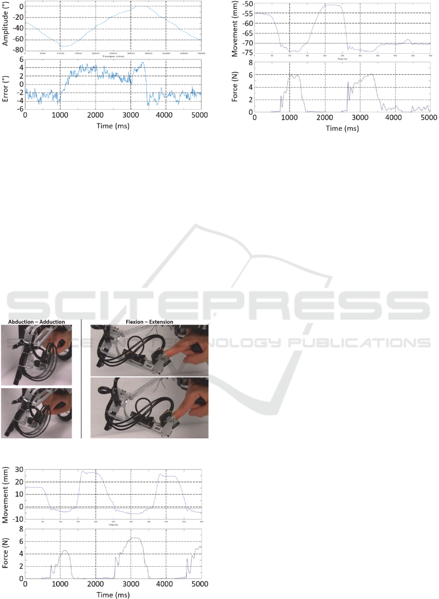
Figure 14: Tracking movement amplitude and tracking
error in flexion-extension.
The error remains below 6° for both movements (for
movements combining abduction and flexion, it
remains below 10°). This is sufficient in practice to
avoid finger end-effector contacts in free space.
4.2 Force Feedback at Contact
We also tested the ability of the device to render
forces in contact. Therefore, we performed
movements in abduction-adduction and flexion-
extension of relatively small amplitude to minimize
the influence of the orientation stage (see Figure 15).
The object’s stiffness is arbitrarily set at 1500N/m.
Figure 15: Hand movements for the force feedback tests.
Figure 16: Force tests results in abduction-adduction.
Figure 17: Force tests results in flexion-extension.
Figures 16 and 17 illustrate the results obtained.
We can see that the force is effectively null in free
space and appears only when touching the
environment as expected.
5 CONCLUSIONS AND
PERSPECTIVES
This paper presents the design and preliminary
evaluation of a novel haptic interface that is both
dexterous and of encounter type. First results show
that this device performs well both in tracking the
fingertip of the index in orientation and in applying
force on it, thus validating the proposed design.
Future work will concern both the management of the
transition between both modes and the control of the
thumb’s robot. In a longer term, we plan to couple this
interface with a VR application allowing to test its
ability to perform dexterous tasks in VR with a high
degree of realism. A particular attention should be
given to the simulation of the friction between the
fingers and the grasped object, using e.g. an advanced
Coulomb-Contensu model as in (Gosselin et al.,
2020), in order to be able to render a tight or a loosen
grip in a natural way. On a longer term, the passive
counterbalancing system should be replaced with an
active carrying robot in order to allow rendering
torques on the palm. Finally, we also intend to work
on the development of an encounter type palm
tracking system.
ACKNOWLEDGEMENTS
This research was partly supported by the “Agence
Nationale de la Recherche” (Mandarin project -
ANR-12-CORD-0011, labeled by “Cap Digital Paris
Région”, the French cluster for digital contents and
ICINCO 2020 - 17th International Conference on Informatics in Control, Automation and Robotics
428

services), and partly accomplished within the
laboratory of excellence SMART supported by
French state funds managed by the ANR within the
Investissements d’Avenir program (ANR-11-IDEX-
0004-02).
REFERENCES
Achhammer, A., Weber, C., Peer, A., Buss, M., (2010),
Improvement of model-mediated teleoperation using a
new hybrid environment estimation technique, Proc.
IEEE Int. Conf. on Rob. and Autom., pp. 5358–5363.
Chabrier, A., Gosselin, F., Gonzalez, F., Bachta, W.,
(2017), Design and experimental evaluation of an
infrared instrumentation for haptic interfaces, Proc.
IEEE Int. Instrumentation and Measurement
Technology Conf., pp. 724-729.
De Araujo, B.R., Guerreiro, T., Fonseca, M.J., Jorge, J.A.,
Pereira, J.M., Bordegoni, M., Ferrise, F., Covarrubias,
M., Antolini, M., (2010), An haptic-based immersive
environment for shape analysis and modelling, Journal
of Real-time Image Processing, 5, pp. 73–90.
De La Cruz Fierro, O., Bachta, W., Gosselin, F., Morrel, G.,
(2017), A New Control Strategy for the Improvement
of Contact Rendering with Encounter-Type Haptic
Displays, Proc. Int. Conf. on Informatics in Control,
Automation and Robotics, pp 471-480.
Fang, H., Xie, Z., Liu, H., (2009), An exoskeleton master
hand for controlling DLR/HIT hand, Proc. of the IEEE
Int. Conf. on Intel. Robots and Systems, pp. 3703–3708.
Feix, T., Pawlik, R., Schmiedmayer, H.B., Romero, J.,
Kragic, D., (2009), A Comprehensive Grasp
Taxonomy, Robotics, Science and Systems Conference:
Workshop on Understanding the Human Hand for
Advancing Robotic Manipulation.
Frisoli, A., Simoncini, F., Bergamasco, M., Salsedo, F.,
(2007), Kinematic design of a two contact points haptic
interface for the thumb and index fingers of the hand,
ASME Journal of Mechanical Design, 129.5, pp. 520–
529.
Gonzalez, F., Gosselin, F., Bachta, W., (2014), Analysis of
hand contact areas and interaction capabilities during
manipulation and exploration, IEEE Trans. on Haptics,
7(4), pp. 415-429.
Gonzalez, F., Bachta, W., Gosselin, F., (2015a), Smooth
transition-based control of encounter-type haptic
devices, Proc. IEEE Int. Conf. on Robotics and
Automation, 2015, pp. 291-297.
Gonzalez, F., Gosselin, F., Bachta, W., (2015b), A 2D
infrared instrumentation for close-range finger position
sensing, IEEE Trans. on Instrumentation and
Measurement, 64(10), pp. 2708-2719.
Gosselin, F., (2016), Modern devices for telesurgery, The
e-medecine, e-health, m-health, telemedicine and
telehealth handbook, CRC Press, Taylor and Francis,
Vol. 2, Section 1, pp. 37-59.
Gosselin, F., Andriot, C., Keith, F., Louveau, F., Briantais,
G., Chambaud, P., (2020), Design and integration of a
dexterous interface with hybrid haptic feedback, Proc.
Int. Conf. on Informatics in Control, Automation and
Robotics, 9 pages.
Gosselin, F., Jouan, T., Brisset, J., Andriot, C., (2005),
Design of a wearable haptic interface for precise finger
interactions in large virtual environments, Proc. IEEE
Worldhaptics Conf., pp. 202–207.
Heo, P., Min Gu, G., Lee, S.J., Rhee, K., Kim, J., (2012),
Current Hand Exoskeleton Technologies for
Rehabilitation and Assistive Engineering, Int. J.
Precision Engineering and Manufacturing, 13(5), pp.
807-824.
Hirota, K., Hirose, M., (1993), Development of surface
display, Proc. IEEE Virtual Reality Annual
International Symposium, pp. 256–262.
Massie, T., Salisbury, J.K., (1994), The PHANTOM haptic
interface: A device for probing virtual objects, Proc.
ASME Symp. on Haptic Interfaces for Virtual
Environment and Teleoperator Systems, pp. 295–299.
McNeely, W., (1993), Robotic graphics: a new approach to
force feedback for virtual reality, Proc. IEEE Int. Symp.
on Virtual Reality, pp. 336 –341.
Nakagawara, S., Kajimoto, H., Kawakami, N., Tachi, S.,
Kawabuchi, I., (2005), An encounter-type multi-
fingered master hand using circuitous joints, Proc.
IEEE Int. Conf. on Rob. and Autom., pp. 2667–2672.
Perret, J., Kneschke, C., Vance, J., Dumont, G., (2013),
Interactive Assembly Simulation with Haptic
Feedback, Assembly Automation, 33 (3), pp. 214-220.
Perret, J., Vander Poorten, E., (2018), Touching Virtual
Reality: A Review of Haptic Gloves, Proc. Int. Conf.
on New Actuators, pp. 270-274.
Plumet, F., Morel, G., Bidaud, P., (1995), Shall we use a
dynamic model to control the motions of industrial
manipulators?, Proc. 9th World Congress on the Theory
of Machines and Mechanisms, pp. 235–240.
Tachi, S., Maeda, T., Hirata, R., Hoshino, H., (1994), A
construction method of virtual haptic space, Proc. Int.
Conf. on Art. Real. and Tele-Existence, pp. 131–138.
Tan, H.Z., Srinivasan, M.A., Eberman, B., Cheng, B.,
(1994), Human factors for the design of force-reflecting
haptic interfaces, Dynamic Systems and Control, 55.1,
pp. 353-359.
Yokokohji, Y., Hollis, R.L., Kanade, T., (1996), What you
can see is what you can feel – development of a
visual/haptic interface to virtual environment, Proc.
IEEE Virtual Reality Annual Int. Symp., pp. 46–53.
Yokokohji, Y., Muramori, N., Sato, Y., Yoshikawa, T.,
(2005), Designing an encountered-type haptic display
for multiple fingertip contacts based on the observation
of human grasping behaviors, International Journal of
Robotics Research, 24(9), pp. 717–729.
Yoshikawa, T., Nagura, A., (1997), A touch and force
display system for haptic interface, Proc. IEEE Int.
Conf. Rob. Autom., pp. 3018–3024.
Yoshikawa, T., Nagura, A., (1999), A three-dimensional
touch/force display system for haptic interface, Proc.
IEEE Int. Conf. on Robot. and Autom., pp. 2943-2951.
Design and Preliminary Evaluation of a Dextrous Encounter Type Force Feedback Interface
429
