
Structured Planning of Hardware and Software Co-simulation Testing of
Smart Grids
Rami Elshinawy
a
, Rebeca P. Ram
´
ırez Acosta
b
, Jan S
¨
oren Schwarz
c
and Sebastian Lehnhoff
d
OFFIS Institute, Escherweg 2, Oldenburg, Germany
Keywords:
Co-simulation, HIL, HTD, Information Model, SGAM, Simulation, Simulation Planning, Smart Grid.
Abstract:
The traditional electricity grid is ought to become a smart grid. One reason is the integration of volatile
renewable energy generation, which poses the demand for advanced communication and control technology.
This results in a change of the overall system dynamics, which in turn require testing to be done in early stages
and with a more holistic approach. However, there is a gap in the transition from system specification and static
analysis to an experimental setup validating these specification. This paper demonstrates first steps towards a
structured methodology for deriving validation experiments for smart grids from initial system requirements.
Our approach aims to fill the introduced gap by integrating Smart Grid Architecture Model (SGAM) for static
analysis, Holistic Testing Description (HTD) for experimental analysis, and additional tools in a new workflow.
Initial assessment of the workflow has been validated on its ability to select the most suitable components and
test beds to perform an experiment. Therefore, two case studies were selected, one in the electricity power
domain and another in the electricity market domain.
1 INTRODUCTION
The new power grid consists not only of physical
electrical equipment (e.g., transformer, cables, etc.),
but also Information and Communication Technol-
ogy (ICT) and the automation of these equipment
adds new domains and dimension to the complexity
of this system. The main reason behind the integra-
tion of these technologies is the introduction of decen-
tralised generation resources and renewable energy in
the efforts to dramatically reduce energy sector emis-
sion levels. These new concepts of energy generation
require constant monitoring and prediction, as they
are intermittent, weather dependent, and have limited
storage capacity. Due to their flexibility and the dy-
namic of the grid, communication and control sys-
tems as well as new electricity market options need
to be tested at earlier stages.
This evolution transforms the traditional electri-
cal grid to a smart grid. This grid has physical de-
vices transferring power and software administrating
the interaction between them. The emerging Cyber
a
https://orcid.org/0000-0002-2803-2499
b
https://orcid.org/0000-0002-9876-8338
c
https://orcid.org/0000-0003-0261-4412
d
https://orcid.org/0000-0003-2340-6807
Physical Energy System (CPES) in hand comprises
of different disciplines and mixed technologies. A
complex configuration, as described, demands testing
the integration of its constituents on a system level,
not only testing of certain aspects of it, addressing all
relevant domains. Moreover, the testing procedure is
required to follow a multi stage process alongside de-
velopment, and before roll out (Van Der Meer et al.,
2017). A well established approach for the analysis of
smart grids and the development of its components is
the use of simulations (Hartmann, 2009). These simu-
lations may be purely software based (Schloegl et al.,
2015) or can contain a real hardware setup (Nguyen
et al., 2017).
Despite the readily available tools for testing and
validation, developing a test for this complex system
is an issue of forming a clear test objective, besides a
specific and relevant multi domain test environment
(Blank et al., 2016). Test standards usually devel-
oped within specific context of a scientific or techni-
cal application. For example, organisations within au-
tomotive, thermal systems or electric power domains
each identify and maintain their specific standards,
test requirements, protocols, and test environments
(Heussen et al., 2019). However, multi domain testing
requires integration of a more fragmented knowledge,
which has been addressed in the context of the Eu-
Elshinawy, R., Acosta, R., Schwarz, J. and Lehnhoff, S.
Structured Planning of Hardware and Software Co-simulation Testing of Smart Grids.
DOI: 10.5220/0009820701970208
In Proceedings of the 10th International Conference on Simulation and Modeling Methodologies, Technologies and Applications (SIMULTECH 2020), pages 197-208
ISBN: 978-989-758-444-2
Copyright
c
2020 by SCITEPRESS – Science and Technology Publications, Lda. All rights reserved
197

ropean ERIGrid project (M
¨
aki et al., 2016; Heussen
et al., 2019; Van Der Meer et al., 2017). Thus, the dis-
ciplinary and methodological framing of experiments
is becoming a challenge itself, especially when form-
ing a ”holistic” test objective and designing experi-
ments for this objective.
The aim of this paper is to propose a workflow
for simulation experiments that reduces the gap in the
transition between specification and static analysis of
a complex system on one hand, and operational test-
ing on the other hand (see section 3). This approach is
built upon integrating wide range of tools and knowl-
edge developed in the literature, taking into consider-
ation the increased number of stakeholders involved
and their business opportunities (see section 2). In
section 4, two case studies are presented for evalua-
tion of the workflow on experiments applied in dif-
ferent domains of the smart grid. Finally, the con-
tribution is concluded and ideas for future work are
elaborated in section 5.
2 FOUNDATIONS AND RELATED
WORK
The approach presented in this paper bases on differ-
ent tools and methods, which will be introduced in
the following. We will give a brief introduction to
the concept of co-simulation in section 2.1 and to the
Holistic Testing Description (HTD) procedure in sec-
tion 2.2. An overview of the Smart Grid Architec-
ture Model (SGAM) and its corresponding utilisation
from a use case description is given in section 2.3.
Approaches for simulation planning are summarized
in section 2.4. Finally, electricity market mechanisms
testing is briefly discussed in section 2.5.
2.1 Co-simulation
As components in smart grid are highly intercon-
nected, test cases quickly become too complex for
pure analytical handling. Therefore, simulation based
experiments are important intermediate step for the
validation process (Steinbrink et al., 2018). As sim-
ulators have been developed to cover only one re-
search area or domain, simplifying the effect of other
connected domains, co-simulation has been devel-
oped, which consists of multiple simulators coupled
together by a software interface. Each simulator may
cover a different aspect of the smart grid. Together,
the simulators allow researchers to analyze complex
interactions and dynamics in more detail (Vogt et al.,
2018).
Co-simulation consists of independently devel-
oped and implemented simulation models. Thus,
each simulator has its own solver and works simul-
taneously and independently on its own model. The
coupled simulators dynamically interact through their
model’s input and output variables, so that the out-
puts of one simulator become the inputs of the other
and vice versa (Palensky et al., 2017). The synchroni-
sation and execution process is controlled during run-
time by a master algorithm that orchestrate the simu-
lation.
The concept of co-simulation does not only focus
on pure software simulation. The setup might include
hardware and software interaction as in Hardware-in-
the-Loop (HIL) experiments. In this approach, a real
hardware setup for a domain (or part of a domain)
is coupled with a simulation tool to allow testing of
hardware components under realistic conditions. The
execution of the simulator in that case requires strictly
small time steps in accordance to the real-time con-
straints of the physical target (Nguyen et al., 2017).
2.2 Holistic Testing Description (HTD)
The project ERIGrid proposed a methodology, that
can be used to plan experiments in smart grid con-
text to account for multi domain systems and varied
experimental platforms, nonetheless improving repro-
ducibility of experiment results. This method is called
Holistic Testing Description (HTD) (Heussen et al.,
2019). The template-based approach consists of three
main documents that abstract the test objective from
the testbed. Each document gives a different view of
the system, filling these documents in order gradually
gives a more concrete view of this System Configura-
tion (SC). These documents are as follows (Heussen
et al., 2017; Van Der Meer et al., 2017):
1. Test Case (TC)
The starting point of HTD procedure is defining
a test case. The inputs are the Generic System
Configuration ((G)SC) and its corresponding Sys-
tem under Test (SuT), which describes the system
boundary in which the Object under Investigation
(OuI) lies, a list of use cases that could be realised
by this test object, and finally the test objective,
which declares the Purpose of Investigation (PoI).
From this, the Domain under Investigation (DuI)
could be defined, additionally the use case de-
scription would help define the Functions under
Test (FuT) and choose the Function under Inves-
tigation (FuI).
2. Test Specification (TS)
After identifying the SuT and the OuI, the test
specification template is of help in identifying
SIMULTECH 2020 - 10th International Conference on Simulation and Modeling Methodologies, Technologies and Applications
198

the concrete Test Specification System Configu-
ration (TS-SC) which is more granular in respect
of equipment number and specific connections.
The test design and the input/output parameters
are also identified in this stage.
3. Experiment Specification (ES)
The final stage is to map the testing requirement
and the SC to a testbed or collection of testbeds
in an integrated experiment, describing its config-
uration. It is important to be noted, that the test
system is separated from the experiment realiza-
tion, which could allow the test system to be real-
ized on separate testbeds.
The mapping procedure, that realizes the test de-
scription on a testbed, can be semi-automated as sug-
gested by (Heussen et al., 2019). This can be achieved
by developing a database that stores information ob-
jects about test laboratories and co-simulation soft-
ware as assets, and a method for selecting the appro-
priate tesbed and its integrated component for test re-
alization according to the test objective and test de-
veloper requirements.
The database will give information on the avail-
able testbed components and their connection possi-
bilities. The selection method describes a two-stage
process for deriving an experiment implementation
from a given test specification. During the process the
test developers are asked to assess the degree of pre-
cision to which the experimental setup needs to repli-
cate various aspects of the test specification (e.g., grid
topology, communication system, static and dynamic
parameters), by examining each aspect (component or
sub-system) of the test system and assigning one of
four different precision levels to it:
Precise. The respective component has to be
matched 1:1 (real hardware).
Equivalent. The respective component has to be
matched equivalently in a dedicated software sim-
ulation tool (e.g., grid topology modelled in Pow-
erFactory), or emulation based manner (e.g., com-
munication network emulator, real time electric
grid simulator, etc.)
Nominal. The respective component can be matched
in a software based manner with some deviations,
but they should only lead to marginal influences
on objective and results (e.g., CSV file time series
of a household load, storage module that can be
used as heat or electricity storage)
Irrelevant. The respective system aspect does not in-
fluence the test objective and results.
The result of the assessment phase is pairing each sys-
tem aspect with a precision category. The assessment
can be used to communicate the fixed implementa-
tion requirements of a test and to prioritize the rest of
the system aspects. These constraints, together with
the prioritization, enable an iterative search of the
database. Consequently, the above mentioned sug-
gestion is applied in our approach as the core of our
assisted testbed mapping procedure.
2.3 SGAM
In order to enable the seamless interaction between
automation components across all sectors of the
new smart grid the Gridwise Architecture Council
(GWAC) introduced the concept interoperability to
the electric power infrastructure (GridWise Architec-
tural Council, 2008) by defining a framework consist-
ing of eight interoperability categories. This will re-
sult in a more cost effective integration of new com-
ponents, easier system update and replacement (CEN-
CENELEC-ETSI Smart Grid Coordination Group,
2014).
According to the GWAC, architecture is the next
category after a framework, ”architectures are the
blueprints for solutions addressing the issues identi-
fied in the framework”. It is the right path towards
more specific solution but also neutral regarding tech-
nology (CEN-CENELEC-ETSI Smart Grid Coordi-
nation Group, 2012b). Accordingly, the Smart Grid
Architecture Model (SGAM) condensed the eight in-
teroperability categories into five layers. Each layer
is applied on the power grid, which has a hierarchy of
automation functionality (Neureiter et al., 2016).
2.3.1 Interoperability Layers
The five SGAM layers represent the first dimension
of this three dimensional architecture model, and are
described as follows (CEN-CENELEC-ETSI Smart
Grid Coordination Group, 2012b):
Business. The business layer represents the business
view on the information exchange related to smart
grids. Regulatory and economic structures can be
mapped on this layer. It supports business execu-
tives in decision making related to business mod-
els and specific business cases.
Function. The function layer describes functions and
services including their relationships from an ar-
chitectural viewpoint. The functions are derived
by extracting the use case functionality, which is
independent from actors.
Information. The information layer represents the
information models, that are used to exchange in-
formation between functions. It contains infor-
mation objects and the underlying canonical data
Structured Planning of Hardware and Software Co-simulation Testing of Smart Grids
199

models. These represent the common semantics
for functions and services in order to allow an in-
teroperable information exchange via communi-
cation means.
Communication. The communication layer is to de-
scribe protocols and mechanisms for the interop-
erable exchange of information between compo-
nents in the context of the underlying use case.
Component. The component layer is the physical
distribution of all participating components in the
smart grid context. This includes system actors,
applications, power system equipment, protection
and telemetry devices, network infrastructure, and
any kind of computers.
The other two dimensions reside on the smart grid
plane as value creations chain (Domains) and automa-
tion pyramid (Zones) (Uslar et al., 2019) controlling
the energy supply chain. The SGAM primarily pro-
vides a general reference in how to architect smart
grids.
2.3.2 Mapping of Use Cases to SGAM
As software development is becoming an integral part
of a smart grid architecture, methods from this dis-
cipline has been adopted for modelling smart grids;
such as utilization of use cases for requirement engi-
neering. Today, the IEC 62559-2 Use Case Template
is a broadly accepted structure for describing smart
grid related use cases (Binder et al., 2019). A method
for use case mapping to an SGAM framework is in-
troduced in (CEN-CENELEC-ETSI Smart Grid Co-
ordination Group, 2012b; Neureiter et al., 2016) and
described in the following paragraphs.
The initial step is extracting information such
as name, scope and objective, use case diagram,
actor names, use case steps, information which is
exchanged among actors, and functional and non-
functional requirements. This information are en-
sured to be provided, if the use case template IEC
62559-2 is used. Actors can be of type devices, ap-
plications, persons, and organizations. These can be
associated to domains relevant for the underlying use
case and mapped to the component layer. The busi-
ness layer is intended to host the business processes,
services and organizations which are linked to the use
case to be mapped.
A use case consists of several sub use cases with
specific relationships, these sub use case can be trans-
formed to functions when formulating them in an
abstract and actor independent way. The informa-
tion layer consists of objects which are exchanged
between actors and derived from the use case de-
scription in form of use case steps and sequence di-
agrams. The communication layer contains protocols
and mechanisms for the interoperable exchange of in-
formation between the components.
2.4 Simulation Planning
While co-simulation and hardware experiments can
be used for testing the dynamic behavior of the smart
grid and the SGAM can be used for the static plan-
ning and evaluation of the smart grid, an integrated
process combining these approaches would be ben-
eficial. Based on the more abstract planning in the
SGAM, concrete simulation scenarios should be de-
veloped, which allow more detailed testing.
Binder et al. have already worked on this chal-
lenge (Binder et al., 2019). The purpose of their
contribution is to allow a quick repetition between
the problem definition and the generation of code
using specific toolchain methodology. The method
adopted Model Driven Engineering (MDE) for auto-
mated and rapid code generation for simulation com-
ponents. However, their approach focuses on the gen-
eration of code based on activity diagrams and does
not support the integration of already existing simula-
tion components.
In their publication (Uslar et al., 2019), the authors
suggested that the SGAM view on the system could
be considered as input information for the specifica-
tion of HTD test cases. Thus, a new workflow could
be realized that starts with an SGAM model and use
case based representation of a desired smart grid setup
and has test developers derive TCs from it, following
the HTD until the experiment implementation, result-
ing in the validation of all crucial parts of the system.
A process for the simulation planning based on
an information model and catalogs with available
co-simulation components is described in (Schwarz
et al., 2019). The information model describes the
data structure for the modeling of a co-simulation
scenario. The co-simulation components available
for coupling in a scenario are collected in a cata-
log. This approach is implemented based on Seman-
tic Web technologies. The information model is mod-
eled as an ontology and the catalogs are realized in a
Semantic Media Wiki (SMW). With the Page Forms
extension for the SMW a form for the definition of
components is build, which provides a questionnaire
for new components. With the catalogs of simulation
components, the development of co-simulation sce-
narios can be assisted, as described in (Schwarz and
Lehnhoff, 2019).
SIMULTECH 2020 - 10th International Conference on Simulation and Modeling Methodologies, Technologies and Applications
200

2.5 Electricity Market Testing
Electricity market plays a crucial role for the future
development of electricity grid. Thus, its testing is
of high importance for the development and imple-
mentation of future technologies. But, electricity mar-
kets are different from place to place and even in the
same region, it is possible to find different market ap-
proaches. (Barroso et al., 2005) provided an overview
of electricity markets in 23 different countries, and
despite its differences, they classified it considering:
Market Clearing Process: in power pool, bilateral
contract or a mix of them.
Pricing Scheme: like single market price, nodal
pricing or zonal pricing.
But a wide variety of market models and arrange-
ments can be found. Therefore, to derive a market ex-
periment, a proper definition of the roles of the play-
ers involved as well as the specific market type has to
be defined. This section will provide some hints about
how SGAM and HTD methodologies can be used to
perform different electricity market tests.
According to the Smart Grid Reference Archi-
tecture technical report the interoperability between
different actors in the electricity system, is essential
to facilitate a smart market (CEN-CENELEC-ETSI
Smart Grid Coordination Group, 2012b). They define
a smart market as the environment in which energy
products and services are freely traded by many mar-
ket actors.
SGAM uses actors, which represents trading plat-
forms, for electricity and other electricity products
like grid capacity or ancillary services, to defined
market testing. SGAM is also partitioned into hier-
archical zones, that model the information manage-
ment of the electrical process. The operation zone in
SGAM, coordinates the activities in the market zone
to ensure the safety and stability of the grid. Three ar-
eas for energy services are considered: Energy Mar-
ket (Commodity), Grid Capacity Market, and Flex-
ibility Market (Imbalance). (CEN-CENELEC-ETSI
Smart Grid Coordination Group, 2012b).
On the other hand, HTD clustered markets in
two areas: Energy Markets and Ancillary Services.
The components are actors with particular roles
like: BRPs, market operators, retailers, aggregators,
among others. The business models, market struc-
tures, and rules are considered as domain related con-
straints. In addition, a purely market perspective as
OuI is not the main focus of HTD.
Markets (including the stakeholders role) and en-
terprise zones in HTD, are more related to the ICT do-
main, in particular consider Information Technology
(IT), in which the components are functions aimed
at guaranteeing power system stability or energy bal-
ance according to the SuT.
Therefore, to test markets, the roles and system
actors need to be inline for a common understand-
ing of all parties. The Harmonized electricity market
Role Model (HRM) was chosen for most of the cases
(also referenced in SGAM) performed by ENTSO-E
(ENTSO-E, 2019a), in which an actor represents a
party that participates in a business transaction, and
a role is considered as the behavior of an actor or the
activities of the actors. This definition was also fol-
lowed for the market testing presented in this paper.
Finally, both methodologies can be used to de-
scribe an electricity market test, but so far they have
been focusing more on IT (communication devices
and control components) than electricity transactions
like bidding process or marginal cost calculations.
(Do Prado et al., 2019), highlighted the necessity of
new business models to ensure operation optimiza-
tion, flexibility, customer integration, and sustainabil-
ity to promote markets liberalization. For this reason,
we propose a way of mapping the electricity mar-
ket test as part of the structured planning of a co-
simulation.
3 APPROACH
The identification of suitable model and components
for a co-simulation setup is still a challenge for exper-
iments in co–simulation testbeds. The possibilities to
re-use components or models, or even to reproduce
the same experiments when sometimes models dif-
fer on their abstraction level increase this challenge
(Heussen et al., 2019). Our approach implements a
simulation planning mechanism using the concepts
summarised in section 2, that can help in the iden-
tification of the most suitable components or models
to run the desired experiment. Additionally, it sug-
gests a workflow that can lead to seamless transition
between modelling of a system specification and the
simulation setup validating this system. This flow is
semi-automized in order to assist the test developer
in building the most suitable validation experiment,
enhancing the practicality and reducing the time re-
quired in filling the HTD template based documents.
The proposed process is described in detail in sec-
tion 3.1, while its technical integration is shown in
section 3.2.
3.1 Process
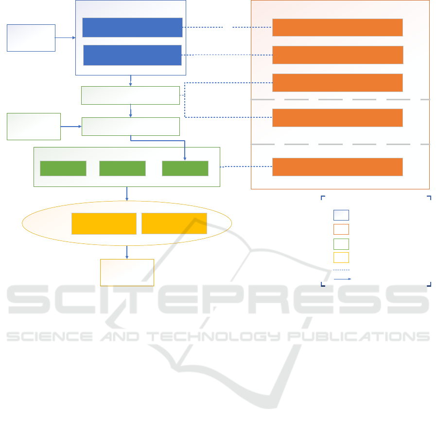
An overview of the proposed process is depicted in
figure 1. It shows the integration of HTD and SGAM
Structured Planning of Hardware and Software Co-simulation Testing of Smart Grids
201
LegendLegend
Use Case
Standard
Description
SGAM
Architectural Layer
Functional Layer
SGAM
Architectural Layer
Functional Layer
Holistic Testing Description (HTD)
Generic System Configuration (GSC)
FuT
PUC
Component Recommender
Test Case System Configuration (TS-SC)
OuI/FuI
Component
Catalogs
Information Model
ComponentsParametersConfiguration
Information Model
ComponentsParametersConfiguration
Experiment Questionnaire
Components + standards
Experiment system configuration (ESC)
Test
Case
Test
Specification
Experiment
Specification
Experiment
Catalog
SGAM
HTD Guideline
Inhouse Developed Tools
Future Work
Mapping/ Realization
Information Flow
Simulation
Use Case
Mosaik Simulation
Scenario
SESA-Lab
Simulation Setup
Simulation
Use Case
Mosaik Simulation
Scenario
SESA-Lab
Simulation Setup
Figure 1: Overview over the process and its alignment with the HTD.
(blue and orange boxes), which is described in section
3.1.1. How this integration can be assisted by ques-
tionnaires and catalogs (green boxes) is introduced in
section 3.1.2 to 3.1.3. Finally, the modeling of a con-
crete experiment (green boxes) is described in section
3.1.4 and the execution in 3.1.5 (yellow boxes).
3.1.1 Integration of HTD Test Case and SGAM
The key aspect of this workflow is the HTD method-
ology. The workflow is aligned with the methodol-
ogy and uses it as a guideline in its three stages de-
scribed in section 2.2. Following the procedure de-
scribed in section 2.3.2, use case description and its
corresponding mapping to the SGAM plan is the ini-
tial step towards modeling of a certain smart grid ar-
chitecture according to the requirements imposed by
the use case description. From an HTD point of view,
this system architecture can be considered as GSC.
Generally a use case description that describe the
system’s main functionality could be decomposed
into several sub use cases as mentioned in section
2.3.2. These granular Primary Use Cases (PUC)
(Neureiter et al., 2016) are transformed to functions
and a collection of them can be selected from HTD
prospective as FuT. Accordingly, the initial steps of
developing the first stage of test case is achieved by
modelling of a system in SGAM and extracting PUC
as FuT.
3.1.2 Experiment Questionnaire
To document the system configuration as well as the
system specification, an experiment questionnaire has
been developed. This questionnaire is subdivided in
a part with general questions and different subsec-
tions for specific domains (e.g., elecricity grid, con-
trol, market, thermal, and ICT). Thus, it can be used
flexibly depending on the domains to be considered.
The questionnaire helps also in selection of suitable
components to run a test.
The system has been described in its generic form,
the test developer has to define the SuT. This is real-
ized by the questionnaire the user has to go through in
order to give a closer look at the boundary of the SuT
with its constituent components and numbers, espe-
cially the OuI. The questionnaire helps to define test
case and test specification terms such as DuI, OuI and
its corresponding FuI, a concrete PoI, and temporal
resolution. The output of the questionnaire represents
the domain independent TS-SC.
SIMULTECH 2020 - 10th International Conference on Simulation and Modeling Methodologies, Technologies and Applications
202

Domain Specific Questionnaire for the Eletricity
Grid. The supply of electricity is done through mul-
tiple stages and different voltage levels. It is important
when developing a test on an electrical equipment, to
know its position in the supply system and the work-
ing voltage level. The questionnaire is dividing the
grid to areas such as generation, transmission and dis-
tribution. Some tests also need grid data that simu-
lates realistic grids, but data from real grids is usually
not public. Therefore, benchmark grids exist in or-
der to test certain developed methodologies and the
questionnaire contains a database of these benchmark
grids to choose from.
Domain Specific Questionnaire for the Electricity
Market. Considering that markets can create op-
portunities for innovative business or solve grid prob-
lems, electricity markets can be designed as engineer-
ing tools, based on simulations (Ringler et al., 2016).
Therefore, a section in the experiment questionnaire
deals with the electricity market to determine the cur-
rent regulatory framework, based on the following at-
tributes:
Market Organization. It considers how the electric-
ity market is organized like: Power pools, bilateral
contracts, or a mix of them. In addition, it asks
for the type of scheduling (central or self) and the
contract’s capability to influence price formation
(physical market contract or only financial market
contract).
Pricing Structure. Considers if the market model,
for the particular study calculates nodal prices or
zonal prices
Trading Time Frame. Scheduling, like day ahead,
intraday and real-time market. But depending on
the simulation, there are some models that focus
more on long-term (one to several years ahead),
medium-term (a week ahead up to two years) and
short-term (a week to a day ahead), for the market
planning or expansion analysis.
Capacity Allocation. Considers how much space
can market participants use on cross border lines
by keeping into consideration the grid topology.
Considers if the regulation asks or not for a con-
gestion management.
Actors Involved. Allowing the selection of the ac-
tors in the current regulation, based on the HRM
(ENTSO-E, 2019a).
The Focal Use Case Collection. (Rossi et al., 2016)
and the challenges for the retail market according
to (Do Prado et al., 2019).
This categorization was elaborated to fit the differ-
ent markets types and use cases found in the liter-
ature (CEN-CENELEC-ETSI Smart Grid Coordina-
tion Group, 2012b; Uslar et al., 2019; M
¨
aki et al.,
2016; CEN-CENELEC-ETSI Smart Grid Coordina-
tion Group, 2012a; Rossi et al., 2016). Considering
that a market test requires knowledge of the condition
of the electrical grid, when a market test is planned,
the questions regarding the required precision of the
grid components for the models as well as the grid
topology are asked.
3.1.3 Component Catalogs
Up to this stage, the developed system is independent
from any testbed environment. In theory, it could be
realized on any test environment. This separation of
test description and its realization on testbed aligns
with the HTD methodology. In order to realize the
test system on a test environment, component cata-
logs for hardware and software objects have been de-
veloped to give an overview of the availability of com-
ponents on certain testbed. In our case, these are the
in house environments such as co-simulation frame-
work mosaik (Steinbrink et al., 2019), or SESA-Lab
(B
¨
uscher et al., 2015). The catalog collects many dif-
ferent categorizations of the components, as described
in (Schwarz et al., 2019). The type of components
were defined based on the documentation from ERI-
Grid (M
¨
aki et al., 2016, p.32ff.), which contains a list
of different domains, areas, levels, components, and
attributes.
The recommendation process of the components
is conducted using the assessment criteria presented
in section 2.2 and a component recommender query-
ing the suitable components according to their pre-
cision level, accordingly the testbed environment is
chosen that contains components fulfilling the re-
quirements presented in the assessment phase. Ex-
amples of this are given in section 4.
3.1.4 Information Model
The ESC has to describe the detailed system config-
uration for a test. To do this in a structured and ma-
chine readable way, an information model (Schwarz
et al., 2019) is used, which allows to model data flows
and parameters of simulation components. Due to
its ontological implementation the content of the in-
formation model is available for querying, which can
also be used for validation of a scenario (Schwarz and
Lehnhoff, 2019). For the modeling of hardware com-
ponents the information models was extended with
additional modeling options for the inputs and outputs
and the topology of the power system.
Structured Planning of Hardware and Software Co-simulation Testing of Smart Grids
203
Choose Coupling
Tool
Experiment
Setup
Coupling Tool Catalog
Experiment Catalog
Component Catalogs
Co-SiCoCa
SESALab-CoCa
Domains,
Components &
Evaluation Criteria
Information Model
Data flows
Transformation functions
Configuration
Experiment Questionnaire
Evaluation Criteria
Holistic Testing Description (HTD)
Requirements
SGAM
Figure 2: Technical Integration Diagram.
3.1.5 Simulation Execution
The development of an executable co-simulation sce-
nario is usually done manually. But based on the de-
scribed previous steps with a formal modeled scenario
based on the information model, the automatic gen-
eration of the executable software co-simulation sce-
nario would be possible and will be future work. For
the execution of a hardware co-simulation the infor-
mation model and the filled out experiment question-
naire could provide a setup for the manual implemen-
tation of the experiment.
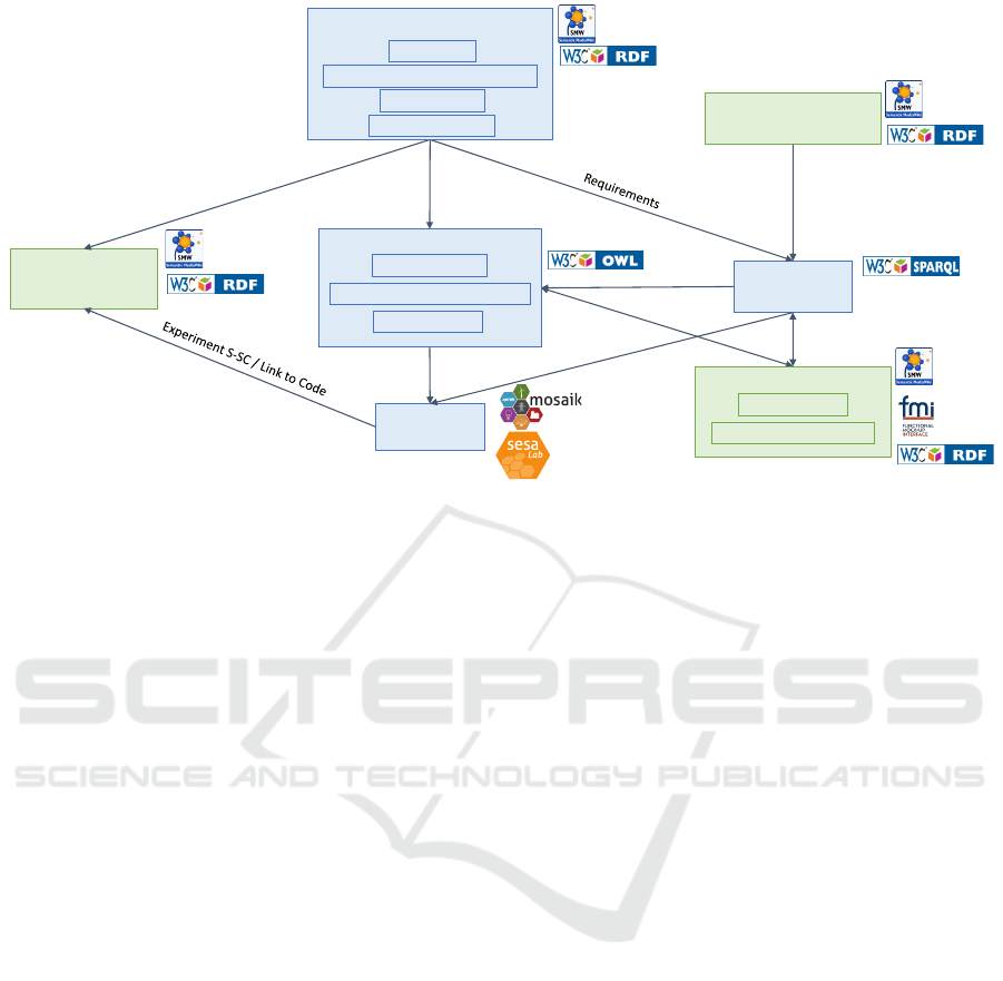
3.2 Technical Integration
The technical implementation of the proposed pro-
cess is shown in figure 2 with the used technologies.
The starting point is the experiment questionnaire in
a SMW, which represents the SGAM and HTD and
also asks for requirements and evaluation criteria of
the experiment. The filled out questionnaire is stored
in an experiment catalog in the SMW to make it avail-
able for reuse or comparison of experiments. The do-
mains, components, and evaluation criteria identified
in the experiment questionnaire can be exported as
RDF from the SMW, so that a direct integration in
the information model is possible.
Based on the requirements, which can be deduced
from the experiment definition, the user could also
be assisted in choosing a suitable coupling tool, e.g.,
mosaik or the SESA-Lab. For this purpose, a ques-
tionnaire for coupling tools has been developed in
the SMW, which makes the characteristics available
for querying with the Semantic Web query language
SPARQL. Especially, the decision between a pure
software co-simulation or an integration of hardware,
can be assisted based on the chosen precision levels
of the components.
Based on the information model, the chosen cou-
pling tool, and the component catalogs in the SMW
the user can get recommendations of suitable simula-
tion components for his experiment and an executable
software or hardware co-simulation scenario can be
build. In the future, the automation of this process
step will be further investigated.
4 EXAMPLES
To evaluate the applicability of our proposed ap-
proach, suitable case studies representing a typical
energy system example have been created. The first
case is to test a new tool, that emulates the behavior
of a real component in the distribution grid. The sec-
ond case study presents a market model simulating a
trading platform for energy flexibility.
4.1 Voltage Regulation on a
Distribution Feeder
In the document (CEN-CENELEC-ETSI Smart Grid
Coordination Group, 2012a) a list of systems that may
form a smart grid has been presented. The aim of the
document is to model smart grid systems or subsys-
tems and investigate the missing standardization in in-
formation and communication interoperability. This
SIMULTECH 2020 - 10th International Conference on Simulation and Modeling Methodologies, Technologies and Applications
204
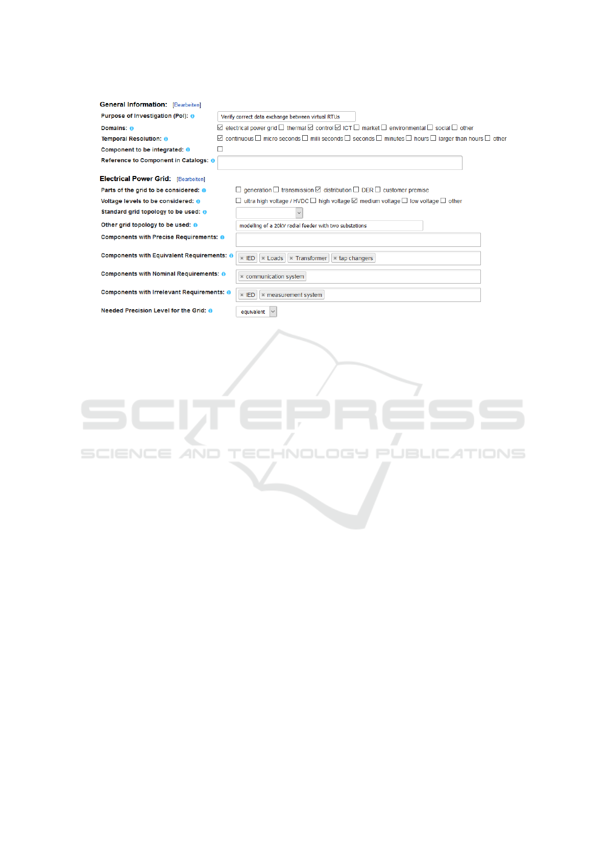
Figure 3: Experiment questionnaire for case study 1.
list is well exhaustive and contains three types of sys-
tems that exists in modern day electricity grid:
Domain specific systems: generation, transmission,
distribution, distributed energy resources, cus-
tomer premises (CEN-CENELEC-ETSI Smart
Grid Coordination Group, 2012b)
Function specific systems: E.g., marketplace sys-
tems, demand flexibility systems, smart metering
systems, weather observation and forecast sys-
tems
Systems that usually focus on administration features:
E.g., asset management, clock reference, commu-
nication management, device management
For the evaluation of the presented process, a sys-
tem configuration for automation of the functions on a
feeder line in the electrical distribution grid has been
chosen. This system is generic enough to contain a
cluster of use cases that could be evaluated separately,
additionally an already in-house publication (Ansari
et al., 2019) that implemented a Test Case in this sys-
tem’s context has been developed. This makes the
feeder automation system an ideal case for the eval-
uation of the suggested process. The developed in
house test system investigates power quality regula-
tion by applying this system’s architecture.
Following the above suggested process, the sys-
tem has been already modeled in SGAM as in (CEN-
CENELEC-ETSI Smart Grid Coordination Group,
2012a) where the use case is chosen to be voltage reg-
ulation of the feeder. A list of PUCs is defined that
collectively achieve this use case. From HTD per-
spective, SGAM modelling defines the generic sys-
tem configuration GSC and FuT, a PoI is defined to
verify the in-house developed virtual Operation Tech-
nologies (OT) such as virtual Remote Terminal Unit
(vRTU) ability to emulate real RTU device function-
ality. The developed questionnaire helps define the
SuT and give a TS-SC as shown in figure 3, addition-
ally the selected components precision level will de-
termine the experiment setup and the simulation envi-
ronment suitable to fulfill the test requirements.
In this case, SESA-Lab was the suitable testbed
for this experiment. The lab contains real time simu-
lator (opalRT) of the electricity grid which aligns with
the selected precision level requirements imposed by
the test developer, as shown in figure 4.
4.2 Market Model Testing
Today’s electricity market design requires evolution
to fit new actors and new technologies (ENTSO-E,
2019b). Some solutions will need to evaluate the con-
gestion management, inclusion of locational signals,
visibility of the resources, trades close to real time,
flexibility markets, among others.
For our market testing use case an active power
flexibility trades scenario was created, in which the
European electricity market was characterized (power
pool price based). This use case idea was based on
(Meibner et al., 2019) and (Uslar et al., 2019).
A generic market trading platform was created in
our component catalog. This platform simulates local
energy exchange to enable energy flexibility, that can
significantly reduce network expansion costs. The
SuT was modeled in SGAM. Only the market, enter-
Structured Planning of Hardware and Software Co-simulation Testing of Smart Grids
205
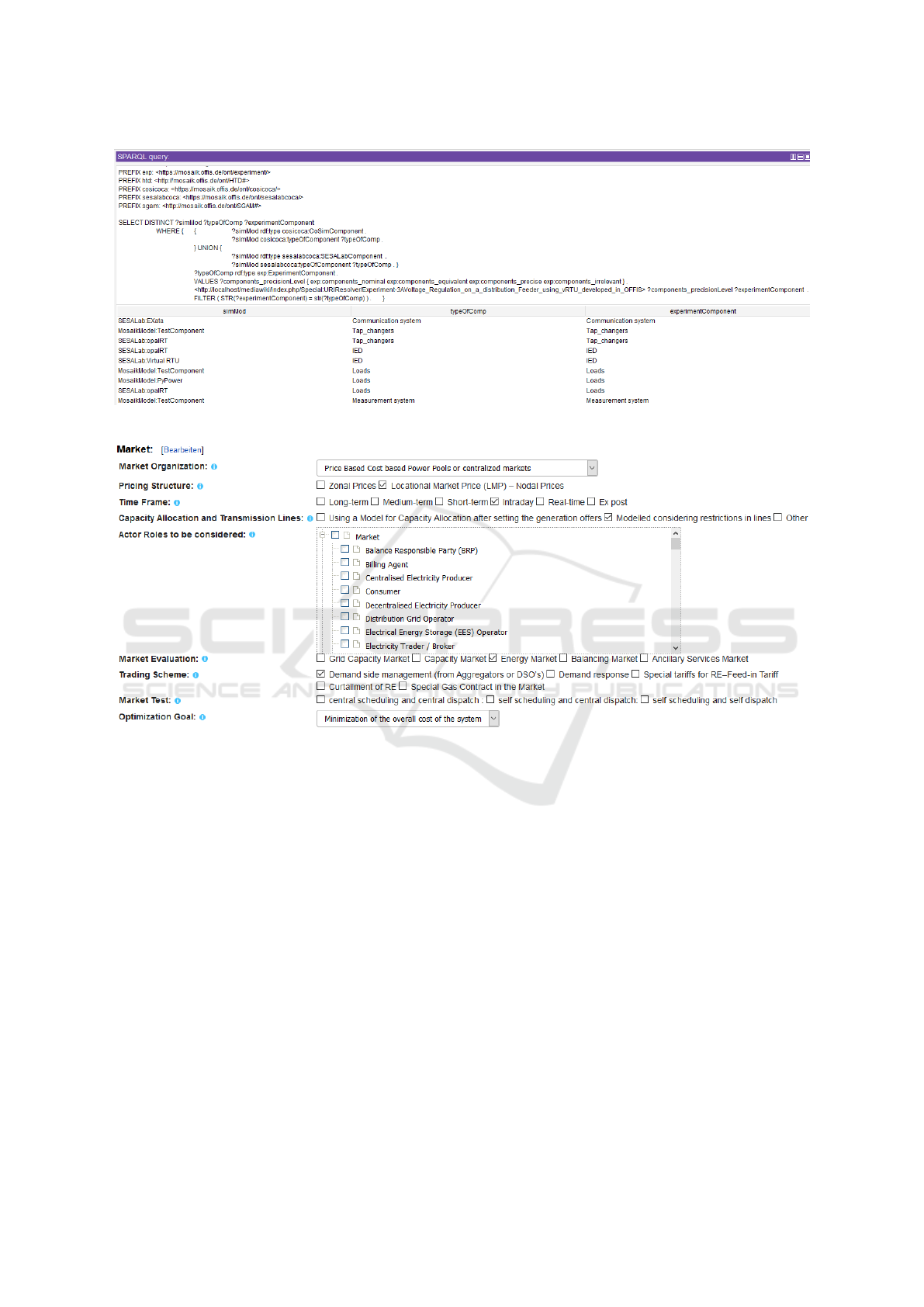
Figure 4: Query to find suitable components for case study 1.
Figure 5: Experiment questionnaire for market model testing (case study 2).
prise and operation zones of SGAM were deployed, in
the distribution domain. The idea of this use case was
to find the suitable components (market trading plat-
form or markets models) to the performed the flexi-
bility analysis modelled in SGAM.
The market trading platform will only match the
bids and reported as a business connection to the
trading partners. The trading partners were a Vir-
tual Power Plant (VPP), that controls and loads with
a flexibility potential, and a Distribution System Op-
erator (DSO) as market agent, that tries to contract
flexibility to avoid congestion.
The categorization helps to seek for a model that
allows price based power pools with Locational Mar-
ket Price (LMP), when the grid is modeled consider-
ing restrictions in lines. The precision level was se-
lected to nominal. Figure 5, shows the market cat-
egorization in the experiment questionnaire express-
ing how the market model or platform should be to
run the use case. These requirements will be used in
a query to propose the better components that fit the
needs. As a result, mosaik was suggested as testbed,
and some other components already implemented in
the catalog were also called for the VPP as well as
loads, DER Units, and a market trading platform de-
scribed for this purpose.
5 CONCLUSION AND FUTURE
WORK
The concepts presented in this paper aim to enhance
existing approaches of smart grid testing and valida-
tion. The proposed workflow draws the initial steps
towards establishing a structured planning procedure
for validation in the smart grid domain, by combining
concepts of static smart grid planning using SGAM
and a holistic test case description method for in-
tegrating multi-domain objectives using HTD. The
SIMULTECH 2020 - 10th International Conference on Simulation and Modeling Methodologies, Technologies and Applications
206

workflow allows test developers to assess which tools
are most suitable to handle their interdisciplinary val-
idation challenges. Additionally, interdisciplinary
testing in a smart grid context becomes more trans-
parent and reproducible. The presented methodol-
ogy is applied internally to include our institute test-
ing infrastructures (mosaik and SESA-Lab), but it
could be extended to include other labs and soft-
ware co-simulation frameworks. Thus, test devel-
opers have the flexibility of developing for example,
multi-platform tests. This can be facilitated by the use
of the Research Infrastructure Database developed in
ERIGrid (Kulmala et al., 2018).
As proof of concept we presented two relevant
case studies. The market model case study is used to
test the dynamics of a trading mechanism before ap-
plying it as regulation and could be sufficiently sim-
ulated in software based matter. The second case
study of voltage regulation in the distribution network
contains transient and dynamic behaviors that could
be simulated properly using hardware components.
The workflow was able to suggest the suitable test-
ing framework following the requirements imposed
by the assessment criteria.
The extension of the experiment questionnaire to
add more detailed questions regarding other domains
such as thermal, control, ICT, environmental and so-
cial domain as well as use cases to test its usability, is
a matter of future work. Additionally, further elabora-
tion of market models in the component catalog will
provide models for specific market studies.
ACKNOWLEDGMENT
This work is funded by the ’6. Energieforschungs-
programm der Bundesregierung’ under project ’MEO
- Modellexperimente in der operativen Energiesyste-
manalyse’ (Grant Agreement No. 03ET4078I).
REFERENCES
Ansari, S., Castro, F., Weller, D., Babazadeh, D., and Lehn-
hoff, S. (2019). Towards virtualization of operational
technology to enable large-scale system testing. In
Proceedings for 2019 Eurocon. IEEE.
Barroso, L. A., Cavalcanti, T. H., Giesbertz, P., and Pur-
chala, K. (2005). Classification of electricity market
models worldwide. 2005 CIGRE/IEEE PES Interna-
tional Symposium, (i):9–16.
Binder, C., Fischinger, M., Altenhuber, L., Draxler, D., Las-
tro, G., and Neureiter, C. (2019). Enabling architec-
ture based Co-Simulation of complex Smart Grid ap-
plications. Energy Informatics, 2(1).
Blank, M., Lehnhoff, S., Heussen, K., Bondy, D. E., Moyo,
C., and Strasser, T. (2016). Towards a foundation for
holistic power system validation and testing. IEEE
International Conference on Emerging Technologies
and Factory Automation, ETFA, 2016-November:1–4.
B
¨
uscher, M., Claassen, A., Kube, M., Lehnhoff, S., Piech,
K., Rohjans, S., Scherfke, S., Steinbrink, C., Ve-
lasquez, J., Tempez, F., and Bouzid, Y. (2015). Inte-
grated Smart Grid simulations for generic automation
architectures with RT-LAB and mosaik. 2014 IEEE
International Conference on Smart Grid Communica-
tions, SmartGridComm 2014, pages 194–199.
CEN-CENELEC-ETSI Smart Grid Coordination Group
(2012a). First Set of Standards. Technical report.
CEN-CENELEC-ETSI Smart Grid Coordination Group
(2012b). Smart Grid Reference Architecture. Tech-
nical report.
CEN-CENELEC-ETSI Smart Grid Coordination Group
(2014). Methodologies to facilitate Smart Grid sys-
tem interoperability through standardization , system
design and testing. (October):1–120.
Do Prado, J. C., Qiao, W., Qu, L., and Ag
¨
uero, J. R. (2019).
The next-generation retail electricity market in the
context of distributed energy resources: Vision and in-
tegrating framework †. Energies, 12(3).
ENTSO-E (2019a). The Harmonised Electricity Market
Role Model, Version: 2019-01. pages 1–21.
ENTSO-E (2019b). Vision on Market Design and System
Operation towards 2030.
GridWise Architectural Council (2008). GridWise Interop-
erability Context-Setting Framework. Technical re-
port.
Hartmann, A. K. (2009). Practical Guide to Computer Sim-
ulations. World Scientific.
Heussen, K., Bondy, D. E. M., Nguyen, V. H., Blank,
M., Klingenberg, T., Kulmala, A., Abdulhadi, I. F.,
Pala, D., Rossi, M., Carlini, C., van der Meer,
A., Kotsampopoulous, P., Rigas, A., Khavari, A.,
Tran, Q. T., Moyo, C., and Strasser, T. (2017). D-
NA5.1 Smart grid configuration validation scenario
description method. Technical report, H2020 ERIGrid
project.
Heussen, K., Steinbrink, C., Abdulhadi, I. F., Nguyen,
V. H., Degefa, M. Z., Merino, J., Jensen, T. V., Guo,
H., Gehrke, O., Bondy, D. E. M., Babazadeh, D.,
Pr
¨
ostl Andr
´
en, F., and Strasser, T. I. (2019). ERI-
Grid Holistic Test Description for Validating Cyber-
Physical Energy Systems. Energies, 12(14):2722.
Kulmala, A., M
¨
aki, K., Rinne, E., Gehrke, O., Heussen, K.,
Bondy, E., Verga, M., Sandroni, C., Pala, D., Nguyen,
V. H., Besanger, Y., Blank, M., Buescher, M., Findrik,
M., Smith, P., Rigas, A., Khavari, A., Cali, M., Sos-
nina, M., Rikos, E., Bhandia, R., Abdulhadi, I., and
Tran, Q. T. (2018). D-NA5.2 Partner profiles. Techni-
cal report, H2020 ERIGrid project.
M
¨
aki, K., Blank, M., Heussen, K., Bondy, E., Rikos, E.,
Rodriguez, E., Merino, J., Blair, S., and Strasser,
T. (2016). D-JRA1.1 ERIGrid scenario descriptions.
Technical report, H2020 ERIGrid project.
Structured Planning of Hardware and Software Co-simulation Testing of Smart Grids
207

Meibner, A. C., Dreher, A., Knorr, K., Vogt, M., Zarif,
H., Jurgens, L., and Grasenack, M. (2019). A
co-simulation of flexibility market based congestion
management in Northern Germany. International
Conference on the European Energy Market, EEM,
2019-September.
Neureiter, C., Uslar, M., Engel, D., and Lastro, G. (2016).
A standards-based approach for domain specific mod-
elling of smart grid system architectures. 2016 11th
Systems of Systems Engineering Conference, SoSE
2016, pages 1–6.
Nguyen, V. H., Besanger, Y., Tran, Q. T., Nguyen, T. L.,
Boudinet, C., Brandl, R., Marten, F., Markou, A.,
Kotsampopoulos, P., van der Meer, A. A., Guillo-
Sansano, E., Lauss, G., Strasser, T. I., and Heussen, K.
(2017). Real-Time Simulation and Hardware-in-the-
Loop Approaches for Integrating Renewable Energy
Sources into Smart Grids: Challenges & Actions.
Palensky, P., Van Der Meer, A. A., L
´
opez, C. D., Joseph, A.,
and Pan, K. (2017). Cosimulation of Intelligent Power
Systems: Fundamentals, Software Architecture, Nu-
merics, and Coupling. IEEE Industrial Electronics
Magazine, 11(1):34–50.
Ringler, P., Keles, D., and Fichtner, W. (2016). Agent-
based modelling and simulation of smart electricity
grids and markets - A literature review. Renewable
and Sustainable Energy Reviews, 57(May 2016):205–
215.
Rossi, M., Carlini, C., Pala, D., Sandroni, C., Strasser, T.,
Rikos, E., Kari, M., Kulmala, A., Rigas, A., Kotsam-
popoulos, P., Van der Meer, A., Bhandia, R., Nguyen,
V. H., Heussen, K., Bondy, D. E. M., Gehrke, O.,
Kosek, A. M., Degefa, M. Z., V
¨
oller, S., Høverstad,
B. A., and Rodr
´
ıguez, E. (2016). D-JRA1.2 Focal
use case collection. Technical report, H2020 ERIGrid
project.
Schloegl, F., Rohjans, S., Lehnhoff, S., Velasquez, J., Stein-
brink, C., and Palensky, P. (2015). Towards a classifi-
cation scheme for co-simulation approaches in energy
systems. Proceedings - 2015 International Sympo-
sium on Smart Electric Distribution Systems and Tech-
nologies, EDST 2015, pages 516–521.
Schwarz, J. S. and Lehnhoff, S. (2019). Ontological in-
tegration of semantics and domain knowledge in en-
ergy scenario co-simulation. IC3K 2019 - Proceedings
of the 11th International Joint Conference on Knowl-
edge Discovery, Knowledge Engineering and Knowl-
edge Management, 2(Ic3k):127–136.
Schwarz, J. S., Steinbrink, C., and Lehnhoff, S. (2019).
Towards an Assisted Simulation Planning for Co-
Simulation of Cyber-Physical Energy Systems. In
7th Workshop on Modeling and Simulation of Cyber-
Physical Energy Systems (MSCPES), pages 1–6,
Montreal.
Steinbrink, C., Blank-Babazadeh, M., El-Ama, A., Holly,
S., L
¨
uers, B., Nebel-Wenner, M., Ram
´
ırez Acosta,
R. P., Raub, T., Schwarz, J. S., Stark, S., Nieße, A.,
and Lehnhoff, S. (2019). CPES testing with mosaik:
Co-simulation planning, execution and analysis. Ap-
plied Sciences, 9(5).
Steinbrink, C., Schlogl, F., Babazadeh, D., Lehnhoff, S.,
Rohjans, S., and Narayan, A. (2018). Future per-
spectives of co-simulation in the smart grid domain.
2018 IEEE International Energy Conference, ENER-
GYCON 2018, pages 1–6.
Uslar, M., Rohjans, S., Neureiter, C., Pr
¨
ostl Andr
´
en, F.,
Velasquez, J., Steinbrink, C., Efthymiou, V., Migli-
avacca, G., Horsmanheimo, S., Brunner, H., and
Strasser, T. I. (2019). Applying the smart grid archi-
tecture model for designing and validating system-of-
systems in the power and energy domain: A european
perspective. Energies, 12(2).
Van Der Meer, A. A., Palensky, P., Heussen, K., Bondy,
D. E., Gehrke, O., Steinbrinki, C., Blanki, M., Lehn-
hoff, S., Widl, E., Moyo, C., Strasser, T. I., Nguyen,
V. H., Akroud, N., Syed, M. H., Emhemed, A., Ro-
hjans, S., Brandl, R., and Khavari, A. M. (2017).
Cyber-physical energy systems modeling, test speci-
fication, and co-simulation based testing. 2017 Work-
shop on Modeling and Simulation of Cyber-Physical
Energy Systems, MSCPES 2017 - Held as part of CPS
Week, Proceedings.
Vogt, M., Marten, F., and Braun, M. (2018). A survey and
statistical analysis of smart grid co-simulations. Ap-
plied Energy, 222(September 2017):67–78.
SIMULTECH 2020 - 10th International Conference on Simulation and Modeling Methodologies, Technologies and Applications
208
