
Investigation of the Dynamic Loads on Tower Cranes During
Slewing Operations
Manuel St
¨
olzner, Michael Kleeberger, Marcel Moll and Johannes Fottner
Chair of Materials Handling, Material Flow, Logistics, Technical University of Munich,
Boltzmannstr. 15, 85748 Garching, Germany
Keywords:
Tower Cranes, Static and Dynamic Analysis, Finite Element Method, Vibration Model, Dynamic Factors.
Abstract:
For decades, tower cranes have been the most important hoisting device used in building construction. In order
to avoid security risks at the construction site, it is essential to analyse the dynamic behaviour of these cranes
during the work process as the crane motions cause dynamic forces on the supporting structure. According
to the current standards, stress calculations for tower cranes are carried out based on static approaches. The
standards stipulate the use of special dynamic factors in the static calculation to estimate the dynamic loads.
This article analyses the dynamic behaviour of a tower crane during the important work process of slewing.
The results of the approach according to the standards are compared with the results of the nonlinear dynamic
finite element calculation. In addition, a newly developed vibration model based on a two-mass model will
be presented in this paper. The model helps to estimate the dynamic loads more accurately than the methods
currently used. However, the computation time required to perform the stress calculation is only slightly
increased.
1 INTRODUCTION
Tower cranes are very versatile and widely used. A
range of tower cranes is available extending from
small cranes, often used for the construction of de-
tached houses, to large tower cranes with special
climbing facilities for the construction of high-rise
buildings. Their field of application currently in-
cludes a hoisting capacity of about 100 metric tonnes,
and a hoisting height of more than 100 metres. In
order to meet the different requirements on construc-
tion sites, most tower cranes are designed modularly,
which enables a large number of boom configurations.
The fundamental motions of tower cranes are
slewing, hoisting and they also allow either a luffing
motion or load travel. During operation, crane mo-
tions cause dynamic forces on the hoist load and on
the crane’s structure. In order to guarantee the safety
of cranes, exact calculations of the boom system are
absolutely essential throughout the developing pro-
cess. Consequently, one main objective of the stress
calculation is to reproduce the system’s dynamic be-
haviour as realistically as possible.
According to the current international standard
ISO 8686 and the European standards EN 13001
and EN 14439, static approaches are used to perform
stress calculations for tower cranes. In order to con-
sider the dynamic effects during the working process,
rigid body approaches are used and special dynamic
factors are defined. These factors are either based on
the experience of the crane manufacturers or alterna-
tively they are selected from tables in the standards.
In this publication, the approaches in the international
standard are evaluated by comparing the calculation
results with the results of other calculation methods.
Some scientific studies on tower cranes are al-
ready available in the literature. However, recent pub-
lications often deal with questions of control engi-
neering to reduce the effects of load swing, e.g. (Le
et al., 2013; Blajer and Kołodziejczyk, 2011; Doc¸i
et al., 2016). In almost all cases, models with rigid
or simple elastic bodies are used. Although these
simplified modelling approaches help to solve control
engineering problems, they are not adequate for in-
vestigating the dynamic effects on the structure in the
stress calculation.
Only a few publications exist that deal with the dy-
namic behaviour of tower cranes taking into account
elastic deformation, or that evaluate the approaches
in the standard. Some papers (Ju and Choo, 2005; Ju
et al., 2006) focus on frequency investigations for dif-
ferent applications. An earlier research project has al-
Stölzner, M., Kleeberger, M., Moll, M. and Fottner, J.
Investigation of the Dynamic Loads on Tower Cranes During Slewing Operations.
DOI: 10.5220/0009816300590067
In Proceedings of the 10th International Conference on Simulation and Modeling Methodologies, Technologies and Applications (SIMULTECH 2020), pages 59-67
ISBN: 978-989-758-444-2
Copyright
c
2020 by SCITEPRESS – Science and Technology Publications, Lda. All rights reserved
59

ready investigated the dynamic loads of tower cranes
when hoisting grounded loads (Maier, 2000). For the
crane analysed, this research project showed that the
dynamic factor for hoisting, according to EN 13001,
describes the loads more accurately than the specifica-
tions in the standard DIN 15018, which is now obso-
lete. However, this work provides no comparison with
the standards for crane movements involving major
displacement of the supporting structure, such as the
process of luffing or slewing.
Since the standards for mobile cranes use similar
approaches for the design, the applicability of the dy-
namic factors has been evaluated in some publications
on mobile cranes, such as (Kleeberger et al., 2014;
St
¨
olzner et al., 2018; St
¨
olzner et al., 2019). These
articles have shown that the simplified approaches of
the calculation methods currently used are often inap-
propriate for reproducing the true dynamic effects on
mobile cranes. As it can be assumed that the calcula-
tion approaches of the standards have similar deficits
for tower cranes as for mobile cranes, the dynamic
behaviour of tower cranes is analysed in more detail
below. Since the publications mentioned above show
that the greatest inaccuracies occur in the calculation
of slewing processes, this article focuses on the dy-
namic loads on tower cranes during slewing.
The nonlinear dynamic finite element method can
characterise the dynamic effects on cranes very accu-
rately. In this article, the results calculated using the
approach from the international standard ISO 8686
are evaluated by means of a comparison with the re-
sults of the nonlinear dynamic finite element calcula-
tion, as this method can be considered reliable.
Although the dynamic finite element method al-
lows exact and reliable calculations, it is very rarely
used by crane manufacturers. The main disadvantage
of this calculation method is the increased computing
effort compared to a static calculation. There is also
no reasonable way to consider the standards’ partial
safety factors in a dynamic calculation.
Alternatively, the standards permit the use of other
methods to calculate the dynamic factors. In order to
achieve a more accurate calculation of the dynamic
behaviour of tower cranes without a disproportionate
increase in computing time, a special vibration model
is presented in this publication. This new method al-
lows the dynamic factors for the slewing process to
be calculated in a more precise way than the current
methods. The applicability of the vibration model and
the calculation standard is shown for a tower crane
with different loads and load positions. In order to
assess the accuracy of the model and the standard,
several angular velocities and angular accelerations of
the tower crane are taken into account.
2 STATE of the ART
The international standard ISO 8686-1 (ISO 8686-1,
2012) defines general rules for the stress calcula-
tion of cranes. With regard to the load assumptions,
the general European standard for crane calculation
EN 13001-2 (EN 13001-2, 2014) is mostly identi-
cal to the international one. The design principles
for loads and load combinations of tower cranes are
specified in the product-specific international stan-
dard ISO 8686-3 (ISO 8686-3, 2018) and in the Eu-
ropean standard EN 14439 (EN 14439, 2010).
In the standards, the approach for considering dy-
namic loads is based on a rigid body kinetic analysis
and uses quasi-static calculation methods. In order to
take the effect of the dynamic forces into considera-
tion, the use of dynamic factors is suggested. How-
ever, the standard ISO 8686-3 also allows other val-
ues to be used for dynamic factors “when determined
by recognized theoretical analysis or practical tests”
(ISO 8686-3, 2018). The nonlinear dynamic finite el-
ement calculation and the vibration model presented
here (see Section 3) both belong to the accepted theo-
retical methods of analysis mentioned above.
To carry out the stress calculation of tower cranes,
the version of the European standard EN 14439 that
is currently valid refers to the now-obsolete stan-
dard DIN 15018 (DIN 15018, 1984) and the guide-
line FEM 1.001 (FEM 1.001, 1998). The interna-
tional standard provides fixed values for the dynamic
factors, whereas the guideline FEM 1.001 defines an-
other method of describing dynamic loads during the
horizontal movements of tower cranes. This guide-
line proposes an approach based on a two-degree-of-
freedom model, which allows the factors to be calcu-
lated depending on the crane configuration (see Sec-
tion 2.2).
In addition to the dynamic factors, both the inter-
national and the European standards prescribe the use
of partial safety factors in order to compensate for un-
certainties in the load assumptions. Since the aim of
this publication is not to evaluate safety factors but to
assess the quasi-static loads from the vibration model
and the calculation standards, no safety factors are
used. Nevertheless, the partial safety factors can be
considered in the same way as prescribed in the stan-
dards when this vibration model is used.
2.1 ISO 8686
The standard ISO 8686-3 “gives specific require-
ments and values for factors to be used at the struc-
tural calculation” (ISO 8686-3, 2018) of tower cranes.
The current draft of the product-specific European
SIMULTECH 2020 - 10th International Conference on Simulation and Modeling Methodologies, Technologies and Applications
60

tower crane standard EN 14439 (prEN 14439, 2018)
corresponds to the approaches of this standard.
Based on ISO 8686-1, the loads are classified as
regular loads, occasional loads and exceptional loads.
The occasional loads include all forces caused by
skewing or loads due to climatic and environmental
influences such as loads from wind, snow or tem-
perature variation. Exceptional loads are test loads
and other loads that occur very rarely during regular
crane operations, for instance loads caused by emer-
gency off or loads due to unintentional loss of the
hoist load. Among regular loads are the forces caused
by “acceleration of all crane drives including hoist
drives” (ISO 8686-1, 2012). The dynamic loads re-
sulting from slewing operations fall into this category
of forces.
According to ISO 8686, the forces applied on
the structure during acceleration and deceleration are
calculated with rigid-body models. The calculation
includes both centrifugal forces and inertial forces.
Since a rigid-body analysis does not reflect the elastic
effects, the changes in the forces are multiplied by a
dynamic factor. To estimate the dynamic loads, the
dynamic factor Φ
5
is defined and some default values
of this factor are proposed in the standard. To con-
sider the inertia forces, the general rules in the stan-
dard ISO 8686-1 provide a range between 1 and 2 for
this factor. The product-specific part ISO 8686-3 de-
fines a factor of Φ
5
= 1.5. The centrifugal forces are
considered by a factor of Φ
5
= 1.
In addition to the proof of strength, ISO 8686-3
also requires a proof of fatigue. As the aim of this
article is not to analyse fatigue, but rather to evalu-
ate and improve the underlying load assumptions, the
proof of fatigue is not considered.
2.2 FEM 1.001
For the proof of strength, the European standard
EN 14439 refers to the FEM guideline 1.001. This
guideline distinguishes between dynamic forces due
to vertical and horizontal movements of the crane. For
the horizontal movements, which include the slewing
process, the guideline defines different dynamic fac-
tors in the stress calculation related to the hoist load
and the supporting structure.
In contrast to ISO 8686, the dynamic factor for the
hoist load is calculated using a two-degree-of freedom
model of the crane (see Figure 1). In this model, m
2
is
the mass of all translatory and rotary moving parts of
the drive system and the supporting structure, reduced
to the load suspension point, while m
1
represents the
mass of the hoist load. The driving force F acts on m
2
.
The stiffness k
1
of the load pendulum is calculated
with the equation
k
1
=
m
1
· g
l
, (1)
where g is the acceleration due to gravity and l is the
length of the pendulum.
Defining the coordinate z = y − x leads to the equa-
tions of motion
m
1
· (¨x + ¨z) = k
1
· z
m
2
· ¨x = k
1
· z − F.
(2)
Solving and evaluating these equations gives rise to a
dynamic factor by which to multiply the inertial force
on the hoist load.
Furthermore, the FEM guideline prescribes a value of
2 as the dynamic factor related to the supporting struc-
ture. To determine this parameter, the square root of
the square sum of the model’s two natural frequencies
ω
a
and ω
b
are calculated ω
r
=
q
ω
2
a
+ ω
2
b
and com-
pared with the time for deceleration.
yx
k
1
m
2
m
1
F
Figure 1: Model according to FEM 1.001.
When applied to the elastic lattice structures of tower
cranes with modern drive systems, this simplified
model has two major disadvantages:
1. The elasticity of the supporting structure is not
considered.
2. The controlled drives currently used for tower
cranes follow the accelerations and decelerations
specified by the crane control very closely. Thus,
the movement of the mass m
2
is determined en-
tirely by the crane control and the two-mass model
is consequently reduced to a one-mass model of
the hoist load’s pendulum.
For these reasons, this simplified model cannot ac-
curately represent the dynamic loads on tower cranes
and the approach is consequently not adopted in the
current draft of EN 14439. Therefore, a modified
two-mass model is presented in the following section
in order to determine the dynamic loads during slew-
ing with an increased accuracy.
3 VIBRATION MODEL
Figure 2 shows the modified vibration model for
calculating the dynamic factors. In comparison to
Investigation of the Dynamic Loads on Tower Cranes During Slewing Operations
61

y
1
x
2
k
1
k
2
m
2
m
1
x
A
(t)
Figure 2: Modified vibration model for calculating dynamic
factors of tower cranes.
Figure 1, an additional spring with the stiffness k
2
is
added to describe the stiffness of the supporting struc-
ture. Furthermore, the displacement x
A
(t) replaces
the driving force F. When the load case slewing is
calculated, x
A
(t) is proportional to the time course of
the slewing angle of the crane slewing gear, which is
determined by the crane control. The dynamic be-
haviour of the supporting structure and the hoist load
can thus be expressed by the equations of motion
m
1
· ( ¨x
1
+ ¨x
2
) + k
1
· x
1
= −m
1
· ¨x
A
(t)
m
2
· ¨x
2
− k
1
· x
1
+ k
2
· x
2
= −m
2
· ¨x
A
(t)
(3)
with x
1
= y
1
− x
2
. The mass m
1
again repre-
sents the mass of the hoist load, the stiffness k
1
is
defined by Eq. 1.
The mass m
2
and the stiffness k
2
are determined
by the results of a frequency analysis of the crane’s
finite element structure. Numerical investigations
about mobile cranes have shown that the vibrations
caused during the slewing process of cranes contain
only few natural frequencies (St
¨
olzner et al., 2018).
During the process of slewing, tower cranes exhibit a
similar dynamic behaviour (see chapter 4.2). Conse-
quently, only the first two lowest natural frequencies
corresponding to the modeshapes, which are orthog-
onal to the plane of the supporting structure, are de-
cisive in analysing the slewing process. ω
1
is usually
the lowest natural frequency of the crane structure at
which the tip of the boom and the hoist load swing
in phase, while ω
2
is the lowest natural frequency at
which the tip of the boom and the hoist load swing out
of phase. The characteristic equation
det
m
1
m
1
0 m
2
· λ
2
+
k
1
0
−k
1
k
2
= 0, (4)
with λ
2
1
= −ω
2
1
and λ
2
2
= −ω
2
2
is used to calculate the
values m
2
and k
2
. The mass m
2
and the stiffness k
2
are finally determined with the equations
m
2
= −
k
2
1
· m
1
k
1
− m
1
· ω
2
1
·
k
1
− m
1
· ω
2
2
(5)
k
2
= −
k
1
· m
1
· ω
2
1
· ω
2
2
k
1
− m
1
· ω
2
1
·
k
1
− m
1
· ω
2
2
. (6)
The differential equations (3) of the two-mass model
can easily be solved analytically. For that reason,
no numerical methods are required for calculating
the dynamic factor, and consequently the proposed
method only needs slightly more computing time than
the method proposed by the standard.
The dynamic factor related to the hoist load and the
supporting structure are calculated with the solutions
x
1
(t) and x
2
(t) of Eq. 3 for the associated working cy-
cle. The solution of the static displacement x
1,m
and
x
2,m
for a constant averaged acceleration a
m
of the
drive system results in the equations
x
1,m
= −
m
1
· a
m
k
2
(7)
x
2,m
= −
(m
1
+ m
2
) · a
m
k
2
. (8)
The displacement solution x
2
(t) is proportional to the
lateral deflection of the boom. As the maximum lat-
eral deflection of the boom is again proportional to the
maximum bending moment in the boom, the largest
absolute value of x
2
(t) at the point in time t = t
max
is,
therefore, relevant for calculating the dynamic factor.
x
1
(t
max
) is the corresponding value of the hoist load’s
lateral displacement. The new dynamic factors for the
static stress calculation result from the quotient of the
calculated dynamic displacements x
1
(t
max
), x
2
(t
max
)
and the static solutions x
1,m
and x
2,m
. The dynamic
factor applied on the supporting structure Φ
5,s
and the
factor for the hoist load Φ
5,p
are calculated with the
relations
Φ
5,s
=
x
2
(t
max
)
x
2,m
(9)
Φ
5,p
=
x
1
(t
max
)
x
1,m
. (10)
Both dynamic factors refer to the inertial forces act-
ing on the crane structure and the hoist load at the
constant mean accelerations a
m
of the slewing drive.
Based on the standard ISO 8686-3, the inertial forces
are still calculated with a rigid-body kinetic model
of the crane, and the dynamic behaviour is estimated
by applying the determined factors Φ
5,s
and Φ
5,p
on the inertia forces. To take the centrifugal forces
into account, the factor of Φ
5
= 1 recommended in
ISO 8686-3 is maintained.
The basic requirement of this vibration model is a
constant natural frequency during the slewing pro-
cess, which is satisfied for both bottom slewing and
top slewing tower cranes. In the case of the bot-
tom slewing tower cranes, the entire structure moves,
which means that the stiffness, and thus also the nat-
ural frequencies of the crane system, do not change.
SIMULTECH 2020 - 10th International Conference on Simulation and Modeling Methodologies, Technologies and Applications
62

For top slewing tower cranes, the natural frequencies
also remain constant, since the tower consists of a
rectangular cross-section and the moment of inertia
is constant in all directions.
4 NUMERICAL ANALYSIS
According to ISO 4306-3 (ISO 4306-3, 2016), the
characteristics of tower cranes can be classified as
assembly, slewing level, type of boom and config-
uration. In the following calculations, a stationary,
top slewing crane with horizontal boom is analysed.
The subsequent sections present the crane with its
analysed parameters (see Section 4.1) and show the
numerical results using different calculation methods
(see Section 4.2).
4.1 Modelling
The calculation of the dynamic loads is based on a
crane with a maximum hoisting capacity of 12 metric
tonnes. In order to investigate the dynamic behaviour
of different crane configurations, the evaluation com-
prises different vertical and horizontal positions of the
hoist load. To analyse the influence of the hoist load’s
vertical position, four different hoisting rope lengths
(0.7 m, 5 m, 10 m, 46 m) are selected (see Figure 3).
No damping is considered in the numerical calcula-
tions because the objective of the investigations is to
assess the accuracy of different approaches for the
stress calculations and not to analyse the influence of
damping on the supporting structure.
The finite element program NODYA, which was espe-
cially developed for the crane calculation, is used to
carry out the calculations. The original focus of this
0.7 m
5 m
10 m
46 m
5 m
75 m
Ê
Ë
Ì
Í
¬
®
¯
Figure 3: Modelling of the tower crane and analysed posi-
tions of the hoist load.
software was the dynamic and static stress calculation
of mobile cranes, but it is also capable of calculat-
ing the lattice boom structures of tower cranes (Maier,
2000). It provides special features for the crane cal-
culation such as a cable element and a superelement.
The load cycle for analysing the dynamic effects
includes the phases acceleration, constant velocity
and deceleration. Linear time courses for the accel-
eration and velocity are assumed, choosing the same
time for acceleration and deceleration (see Figure 4).
The point in time t
max
of the maximum lateral
movement of the boom system is detected with a cho-
sen simulation time of 60 s. To identify the maxi-
mum stress, the calculations are carried out with 11
different time durations of constant velocity t
B
, rang-
ing from 0 s to 20 s. Crane manufacturers often only
consider one acceleration phase, as the crane operator
should commonly choose a convenient braking point
to achieve minimal vibration of the supporting struc-
ture and the load. However, in the modelled process
including the phase of deceleration, the influence of
the crane operator is disregarded as this represents the
more conservative load case.
As described in Section 2.1, the loads calculated
according to the international standard are mainly
dominated by the inertia forces and, therefore, depend
almost entirely on the acceleration of the supporting
structure. To verify this approach and to show possi-
ble dependencies of the dynamic loads on velocity or
acceleration, different combinations of angular speed
and angular acceleration are analysed in the calcula-
tions (see Table 1). As the FEM guideline recom-
mends an acceleration time between 5 s and 10 s, a
time close to this range is selected. In addition, it is
ensured that the drive torques do not exceed a value
of about 400 kN m.
v
a
m
t
B
v
a
m
Acce-
leration
Constant Velocity Dece-
leration
t
a
m
0
−a
m
a(t), v(t)
a(t)
v(t)
Figure 4: Analysed time course of the angular acceleration
and angular velocity of the slewing drive.
Investigation of the Dynamic Loads on Tower Cranes During Slewing Operations
63
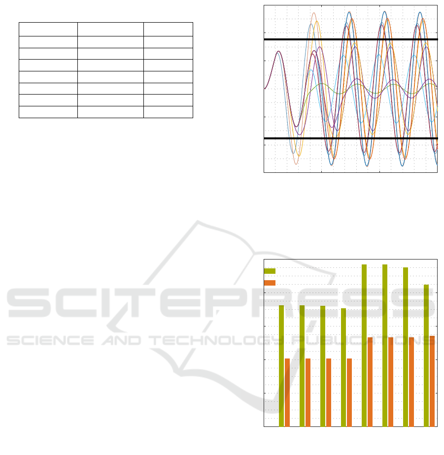
Table 1: Analysed combinations of angular velocity and ac-
celerations.
ω in rad s
−1
˙
ω in rad s
−2
ω/
˙
ω in s
0.0105 0.0015 7
0.0105 0.0021 5
0.0105 0.0026 4
0.021 0.0021 10
0.021 0.003 7
0.0315 0.00263 12
0.042 0.0028 15
4.2 Results
The nonlinear dynamic finite element calculation is
the calculation method that can be considered the
most realistic for cranes. For this reason, the results
obtained from the calculation standard and the vi-
bration model are evaluated by means of comparison
with the results of the dynamic finite element calcula-
tion.
4.2.1 Dynamic Calculation and ISO 8686
Figure 5 shows an exemplary comparison between
the dynamic calculation and ISO 8686-3. The figure
shows the time courses of the lateral deformation of
the boom’s tip regarding 11 different times t
B
between
0 s and 20 s. The maximum values depend strongly
on the point in time at which breaking is initiated and
on the duration of the steady state time t
B
. However,
it is not possible to standardise the most crucial time
t
B
since the time courses change for different crane
configurations and different angular velocities or ac-
celerations. The results of the static calculation ac-
cording to ISO 8686-3 are shown for a positive and
a negative direction of slewing. In the crane configu-
ration considered, the results of the static calculation
are lower than the absolute maximum of the dynamic
calculation.
Figure 6 shows the results of the lateral deformation
of the crane’s boom tip for all load positions ¬-¯ and
Ê-Í of Figure 3. The diagram shows the results for
the combination of velocity and acceleration at which
the maximum lateral displacement of the boom tip oc-
curs. When the angular velocities and accelerations
resulting in the maximum lateral displacement of the
dynamic calculation are analysed, it is noticeable that
the maximum always occurs at the highest considered
acceleration of 0.003 rad s
−2
. This indicates that the
dynamic crane loads depend mainly on the angular
acceleration and not on the angular velocity of the
tower crane, which is analysed more precisely in Sec-
tion 4.2.2. For all velocities and accelerations consid-
ISO 8686-3
ISO 8686-3
Displacement in m
0
1
2
3
1-
2-
3-
Time in s
0 20 40 60
Figure 5: Time courses of the boom tip including dif-
ferent times t
B
, ω = 0.0105 rad s
−1
,
˙
ω = 0.0026 rad s
−2
,
m
1
= 12 t, length of hoisting rope: 10 m, horizontal load
position: 5 m.
Dynamic calculation
ISO 8686-3
Displacement in m
0
1
2
3
4
5
Ê Ë Ì Í¬ ® ¯
Load positions according to Figure 3.
Figure 6: Maximum lateral displacement of all analysed
crane systems, calculated with the dynamic calculation and
according to ISO 8686-3. The maximum is always reached
with ω = 0.021 rad s
−1
and
˙
ω = 0.003 rad s
−2
.
ered, the calculation according to ISO 8686-3 results
values that are too low for the dynamic loads. Fur-
thermore, it is apparent that the differences between
the calculation according to the standard and the dy-
namic finite element calculation occur for all investi-
gated positions of the hoist load.
When we study the dependency of the maximum
lateral displacement on the pendulum length, a de-
creasing crane load is obtained with increasing pen-
SIMULTECH 2020 - 10th International Conference on Simulation and Modeling Methodologies, Technologies and Applications
64

dulum length. For this reason, the requirement of
the standard, which prescribes a load position “at
the top of the jib or immediately below the crab”
(ISO 8686-1, 2012) could be confirmed by these nu-
merical tests.
4.2.2 Dynamic Calculation and Vibration Model
Figure 7 shows a Fourier transformation of the dy-
namic time course of the hoist load’s lateral displace-
ment. In the frequency domain it becomes clear that
the vibration is mainly dominated by two frequencies,
which correspond to the first and the fourth natural
frequency of the crane. Since other frequencies in-
fluence the vibration signal only very slightly, the vi-
bration can be simulated with the developed two mass
model.
Absolute value Fourier coefficient in m
0
0.4
0.8
1.2
Frequency in Hz
0 0.05 0.1 0.2 0.3
Figure 7: Fourier transformation of the hoist load’s lat-
eral displacement, ω = 0.0105 rad s
−1
,
˙
ω = 0.0026 rad s
−2
,
t
B
=10 s, m
1
= 2.5 t, length of hoisting rope: 46 m, horizon-
tal load position: 75 m.
Figure 8 shows the time course of the lateral displace-
ment of the hoist load’s suspension point for both the
dynamic calculation and the vibration model. The vi-
bration model reproduces the time course of the dy-
namic finite element calculation with high accuracy.
Both frequency and amplitude are reproduced almost
exactly as the higher natural frequencies make no no-
ticeable contribution to the vibration. For this rea-
son, the use of only two natural frequencies in the
vibration model shown leads to almost the exact re-
construction of the nonlinear dynamic finite element
calculation.
Dynamic calculation
Vibration model
Displacement in m
0
2
4
2-
4-
Time in s
0 20 40 60
Figure 8: Time course of the hoist load’s suspension point,
ω = 0.021 rad s
−1
,
˙
ω = 0.003 rad s
−2
, t
B
= 14 s, m
1
= 2.5 t,
horizontal load position: 75 m.
Table 2 shows the dynamic factors related to the
hoist load and the supporting structure according to
the Eqs. 9 and 10. The dynamic factors vary consid-
erably, in part, when the different velocities and accel-
erations are used. In all cases, the dynamic factor re-
lated to the hoist load is higher than the factor for the
supporting structure, as an increased inertia force acts
on the hoist load due to the pendulum. Furthermore,
a dependency of the dynamic factor on the angular
acceleration of the crane can be derived, while the
dependency on the angular velocity is considerably
lower. In an earlier publication about mobile cranes, it
was already possible to determine dependency condi-
tions for velocity and acceleration based on the break-
ing time and the period of vibration (Kleeberger et al.,
2014). Since the selected angular acceleration is rel-
atively low in each case, the dependency on the an-
gular acceleration is more significant in the presented
analyses. The analysis of special working conditions,
Table 2: Dynamic factors calculated with the vibration
model, m
1
= 2.5 t, length of hoisting rope: 5 m, load-lifting
radius: 75 m.
ω
˙
ω t
B
Φ
5,s
Φ
5,p
in rads
−1
in rads
−2
in s
0.0105 0.0015 0 1.999 2.017
0.0105 0.0021 2 1.889 1.935
0.0105 0.0026 18 1.752 1.83
0.021 0.0021 12 1.889 1.916
0.021 0.003 0 1.999 2.017
0.0315 0.00263 12 1.717 1.726
0.042 0.0028 18 1.526 1.578
Investigation of the Dynamic Loads on Tower Cranes During Slewing Operations
65

such as the load case emergency stop with its high ac-
celerations, would result in other dependencies. Over-
all, it can be seen that the recommended value of
Φ
5
=1.5, which is specified in ISO 8686-3, cannot lead
to satisfactory results in most cases. The value 1.5 is
only suitable for the longest acceleration time of 15 s.
In Figure 9, the maximum lateral displacements
of the boom’s tip resulting from the dynamic calcula-
tion are compared with the quasi-static calculations.
In order to investigate the quality of the load assump-
tions derived from the vibration model with those of
ISO 8686-3, the results of both methods are included
in the diagram. The quasi-static calculations using
the vibration model are based on the dynamic fac-
tors listed in Table 2. It is obvious that the dynamic
factors based on the vibration model allow a much
more accurate representation of the dynamic calcula-
tion than using the default factor of 1.5 which is spec-
ified in the standard. The dynamic calculation can be
reproduced with high accuracy for all angular veloci-
ties and accelerations by using the calculated dynamic
factors. This clearly shows that the approach of the
quasi-static calculation leads to precise results when
appropriate dynamic factors are used.
Dynamic calculation
Vibration model
ISO 8686-3
Displacement in m
0
1
2
3
4
5
ω = 0.01050 rad s
−1
˙
ω = 0.00150 rad s
−2
ω = 0.01050 rad s
−1
˙
ω = 0.00210 rad s
−2
ω = 0.01050 rad s
−1
˙
ω = 0.00260 rad s
−2
ω = 0.02100 rad s
−1
˙
ω = 0.00210 rad s
−2
ω = 0.02100 rad s
−1
˙
ω = 0.00300 rad s
−2
ω = 0.03150 rad s
−1
˙
ω = 0.00263 rad s
−2
ω = 0.04200 rad s
−1
˙
ω = 0.00280 rad s
−2
Figure 9: Maximum lateral displacement, m
1
= 2.5 t,
length of hoisting rope: 5 m, horizontal load position: 75 m.
5 CONCLUSION AND OUTLOOK
In this paper, the dynamic loads on tower cranes dur-
ing the slewing operation were analysed. The ac-
curacy of the standard ISO 8686-3 was evaluated by
comparing the results with the results of the nonlinear
dynamic finite element calculation. For the crane in-
vestigated in this publication, the dynamic loads were
usually underestimated with the default dynamic fac-
tor stipulated in the standard.
In order to describe the dynamic behaviour of the
tower crane during the slewing operation more ac-
curately, a newly developed vibration model, based
on a two-degree-of-freedom system, was presented in
this article. With the help of this model, the elas-
tic deformations of the supporting structure could be
considered in the stress calculation. It was possi-
ble to determine dynamic factors that allow a more
accurate description of the dynamic loads on tower
cranes than the commonly used factors from the stan-
dard. Concurrently, a similar computing time could
be achieved, since the vibration model is based on an
analytical solution of the two-degree-of-freedom sys-
tem. The comparisons included different angular ve-
locities and accelerations of the driving system and
different positions of the hoist load to determine the
influence of these parameters on the dynamic effects.
By analysing typical working cycles, the risks and
potentials of the current tower crane calculation dur-
ing the slewing process could be shown. The knowl-
edge of the dynamic loads on tower cranes can pro-
vide information about the quality of the standard’s
load assumptions.
To verify the statements on the dynamic properties
and the applicability of the vibration model, system-
atic comparisons including different types of cranes
should be carried out in the future. Furthermore, new
measurements of currently used tower cranes are nec-
essary to obtain further results regarding the accuracy
of the modelled crane and the different calculation
methods. An important question also arises from the
applicability of the vibration model to different work-
ing processes, such as hoisting or luffing.
REFERENCES
Blajer, W. and Kołodziejczyk, K. (2011). Improved
DAE formulation for inverse dynamics simulation of
cranes. Multibody System Dynamics.
Doc¸i, I., Hamidi, B., and Lajqi, S. (2016). Dynamic analy-
sis and control of jib crane in case of jib luffing motion
using modelling and simulations. International Fed-
eration of Automatic Control-PapersOnLine.
Ju, F. and Choo, Y. S. (2005). Dynamic Analysis of Tower
Cranes. Journal of Engineering Mechanics-ASCE.
Ju, F., Choo, Y. S., and Cui, F. S. (2006). Dynamic response
of tower crane induced by the pendulum motion of the
payload. International Journal of Solids and Struc-
tures.
SIMULTECH 2020 - 10th International Conference on Simulation and Modeling Methodologies, Technologies and Applications
66

Kleeberger, M., Schneidler, S., and G
¨
unthner, W. A. (2014).
Untersuchung der dynamischen Beanspruchungen bei
Gittermast-Fahrzeugkranen und Vergleich mit der
quasistatischen Auslegung der Norm. In Tagungs-
band 22. Kranfachtagung. Otto von Guericke Univer-
sity Magdeburg.
Le, T. A., Dang, V.-H., Ko, D. H., An, T. N., and Lee, S.-G.
(2013). Nonlinear controls of a rotating tower crane
in conjunction with trolley motion. Journal of Systems
and Control Engineering.
Maier, K. J. (2000). Untersuchung zur nichtlinearen
Berechnung dynamischer Belastungsvorg
¨
ange an Tur-
mdrehkranen. PhD thesis, Technical University of
Munich.
DIN 15018 (1984). German Institute for Standardization:
Cranes - principles for steel structures - stress analysis.
EN 13001-2 (2014). European Committee for Standardiza-
tion: Crane Safety - General design - Part 2: Load
actions.
EN 14439 (2010). European Committee for Standardiza-
tion: Cranes - Safety - Tower cranes.
FEM 1.001 (1998). Federation Europeenne de la Manu-
tention (FEM): Rules for the design of hoisting ap-
pliances.
ISO 4306-3 (2016). International Organization for Stan-
dardization: Cranes - Vocabulary - Part 3: Tower
cranes.
ISO 8686-1 (2012). International Organization for Stan-
dardization: Cranes - Design principles for loads and
load combinations - Part 1: General.
ISO 8686-3 (2018). International Organization for Stan-
dardization: Cranes - Design principles for loads and
load combinations - Part 3: Tower cranes.
prEN 14439 (2018). European Committee for Standardiza-
tion: Cranes - Tower cranes (Draft).
St
¨
olzner, M., Kleeberger, M., G
¨
unthner, W. A., and Fottner,
J. (2018). Vibration model to describe the dynamic
behaviour of lattice boom mobile cranes and loader
cranes. In Logistics Journal: Proceedings. WGTL.
St
¨
olzner, M., Kleeberger, M., G
¨
unthner, W. A., and Fottner,
J. (2019). Calculating the dynamic behaviour of lattice
boom mobile cranes during hoisting with a vibration
model. In XXIII International Conference on Material
Handling, Constructions and Logistics - MHCL 2019.
Vienna University of Technology (Institute for Engi-
neering Design and Product Development) together
with University of Belgrade (Faculty of Mechanical
Engineering).
Investigation of the Dynamic Loads on Tower Cranes During Slewing Operations
67
